ABSTRACT
RAMAKRISHNA, HARSHINI. Multiphase Biodegradable Scaffolds for Tissue Engineering a Tendon-Bone Junction. (Under the direction of Dr. Martin W. King)
Tendons play an important role in transferring stress between muscles and bones and in maintaining the stability of joints. Tears in the joints have poor healing capacity and the lesions are associated with cartilage degeneration. Therefore, strategies are needed to promote repair and long-term regeneration of such joints. The ultimate goal of this study is to develop a biodegradable scaffold for tendon-bone junction regeneration. As a first step to achieve this, polylactic acid (PLA) yarns were braided into tubular scaffolds and cultured with unique TGF-β Type II receptor-expressing joint progenitor cells under static conditions. The scaffolds were designed to mimic the natural mice tendon-bone junction in terms of its structure, mechanical and immunochemical properties. Two types of PLA yarns were used. Those with round fibers had a 25μm diameter, while those fibers with a 4 deep grooved
Multiphase Biodegradable Scaffolds for Tissue Engineering a Tendon-Bone Junction
by
Harshini Ramakrishna
A thesis submitted to the Graduate Faculty of North Carolina State University
in partial fulfillment of the requirements for the degree of
Master of Science
Textile Engineering
Raleigh, North Carolina 2015
APPROVED BY:
_______________________________ _______________________________
Dr. Martin W. King Dr. Robert Dennis
DEDICATION To my beloved parents
To my friends
BIOGRAPHY
Harshini Ramakrishna was born on 21st February, 1992 in Chennai, Tamil Nadu, India. She is the second daughter to her parents. She completed her high school from SBOA Hr. Sec. School in Chennai. She pursued her Bachelor’s degree in Textile Technology in Alagappa
Chettiar College of Technology, Anna University, Chennai. During her Bachelors, Harshini worked on internships at Meridian Apparels and Arunachala Spinning Mills in Tirupur, India. She received her B.Tech degree in May 2013.
Following her Bachelor’s, Harshini applied to the Master’s program in Textile Engineering at North Carolina State University. She is a member of the Society of Biomaterials, Student Chapter in NCSU. She is an active member and holds the position of Treasurer of the Textile Association of Graduate Students (TAGS) for 2 years from May 2014. She expects to receive her Master of Science degree in December 2015.
ACKNOWLEDGMENTS
I would like to sincerely thank Dr. Martin W. King who has been a constant support and a guiding force during the entire course of this project. He has been a great mentor and has helped throughout my stay here in NC State both professionally and personally. He has always been a source of inspiration for budding Textile Engineers like me and I take great pride in calling him my mentor.
I would also like to thank Dr. Robert Dennis, Dr. Wendy Krause and Dr. Susan Bernacki for agreeing to be a part of my advisory committee. They have always been encouraging and provided valuable inputs while I was working on this project. I would like to extend my special thanks to Dr. Anna Spagnoli, Professor and Woman’s Board Chair, Department of Pediatrics at Rush University Medical Center. I am grateful to her and her group members Tieshi Li and Joseph Temple for allowing me to work in their laboratories to make this study a success. My sincere thanks to all the technicians and researchers who have helped me with my study: William Barnes, Tri Vu, Judy Elson and Dr. Eva Johannes. I would also like to thank all the members of Dr. Martin King’s Biomedical Textiles Group for their constant
support. I am especially thankful to Ting He and Yu Xie for helping me with my experimental work.
TABLE OF CONTENTS
LIST OF TABLES --- vii
LIST OF FIGURES --- viii
Chapter 1 Introduction --- 1
1.1 Motivation and Significance --- 1
1.2 Goals and Hypothesis --- 2
1.3 Outline of the Thesis --- 5
Chapter 2 Review of Literature --- 7
2.1 Structure and Properties of Tendon Bone Junction --- 7
2.2. Tendon Bone Junction Injuries --- 17
2.3. Strategies for the Repair and Regeneration of Tendon Bone Junctions --- 21
2.4 Poly(lactic) Acid (PLA) --- 30
Chapter 3 Materials and Methods --- 36
3.1 Fabrication of Scaffolds for Tendon Bone Junction Regeneration --- 36
3.1.1 Preparation of PLA Yarns for Braiding--- 36
3.1.2 Braiding of PLA Yarns --- 40
3.1.3. Morphology by Scanning Electron Microscopy (SEM) --- 42
3.1.4. Total Porosity and Pore Size --- 42
3.2 Mechanical Properties --- 44
3.2.1 Tensile Strength and Elongation at Break --- 44
3.3. In Vitro Cell Culture Study --- 45
3.3.1.1 Sterilization of the Scaffolds --- 46
3.3.2 TGF-β Type II Receptor Expressing Cells Isolation and Seeding --- 46
3.3.3 AlamarBlue™ Assay --- 48
3.3.4. Laser Scanning Confocal Microscope (LSCM) using Live/Dead Stain --- 49
3.3.5. Quantitative Polymerase Chain Reaction (qPCR) --- 51
3.4 Statistics --- 52
Chapter 4 Results and Discussion--- 53
4.1 Characterization of the Braided Scaffolds --- 53
4.1.1 Structure of the Braided Scaffolds--- 53
4.1.2 Basic Properties of the Braided Scaffolds --- 56
4.2 Mechanical Properties --- 58
4.3 Biological Performance of the Scaffolds --- 62
4.3.1 Optical Microscopic Images of Cell Attachment --- 62
4.3.2 AlamarBlue™ Assay --- 64
4.3.3 Laser Scanning Confocal Microscope (LSCM) using Live/Dead Stain --- 67
4.3.4 Quantitative Polymerase Chain Reaction (qPCR) --- 73
Chapter 5 Conclusions and Future Work --- 77
5.1 Conclusions --- 77
5.2 Future Work --- 78
LIST OF TABLES
Table 2.1 Characteristics of fibrous and fibrocartilaginous enthesis [8] --- 12
Table 2.2 Composition and significance of the four zones of an enthesis [8] --- 15
Table 2.3 Properties of poly(lactic) acid fibers [42] --- 35
Table 3.1 Basic properties of the fiber --- 37
Table 3.2 Properties of fully drawn round PLA yarn --- 39
Table 4.1 Basic properties of the three types of braided scaffolds --- 57
LIST OF FIGURES
Figure 2.1 Hierarchical structure of a tendon structure containing collagen molecules, fibrils, fiber bundles, fascicles and tendon units that run parallel to the tendon’s
longitudinal axis [3] --- 8
Figure 2.2 Stress strain curve of a tendon [2] --- 10
Figure 2.3 The four zones of the enthesis viewed in a histological section: Zone 1-Pure dense fibrous connective tissue, Zone 2-Uncalcified fibrocartilage, Zone 3-Calcified fibrocartilage, Zone 4-Bone [8] --- 13
Figure 2.4 Cross-sectional view of a mouse supraspinatus tendon-to-bone insertion where yellow color indicates collagen and blue indicates mineral content [20] --- 18
Figure 2.5 Structure of Achilles tendon [21] --- 19
Figure 2.6 Anatomical location of an anterior cruciate ligament [22] --- 21
Figure 2.7 Anatomy of tendon bone insertion showing the four zones: tendon, uncalcified fibrocartilage, calcified fibrocartilage and bone [25] --- 22
Figure 2.8 Stratified approach strategy [20] --- 23
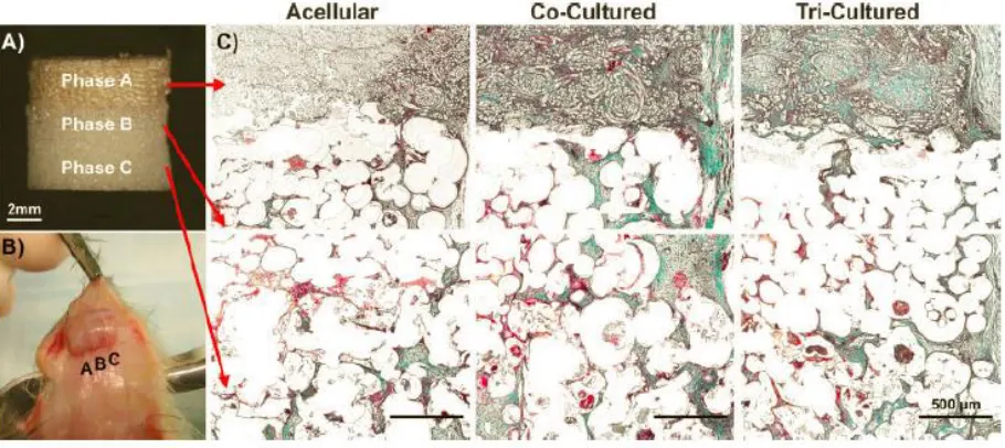
Figure 2.9 (A) Triphasic scaffold with three distinct yet contiguous phases (B) Explanted tricultured scaffold at Week 4. (C) Collagen production (green) on the dorsal side of the acellular, co-cultured and tri-cultured scaffolds after 4 weeks of implantation [24] --- 24
Figure 2.10 (a) Structure of poly(lactic) acid. (b)Enantiomers of lactic acid [38, 39] --- 30
Figure 2.11 Petrochemical route for the production of lactic acid [38, 39] --- 31
Figure 2.12 Lifecycle of poly(lactic) acid [40] --- 32
Figure 2.13 Synthesis of poly(lactic) acid [38,41] --- 33
Figure 2.14 Morphology of 4DG fiber [43]--- 34
Chapter 1 Introduction 1.1 Motivation and Significance
The tendon bone junction is a functionally graded material which helps in transition from a soft unmineralized tendon tissue to hard mineralized bone. It also plays an important role in transferring stresses and in maintaining the stability of joints. Tears in the joints have poor healing capacity and the lesions are associated with cartilage degeneration. The most common tendon bone junction injuries are the achilles tendon injury, rotator cuff injury and anterior cruciate ligament (ACL) injury. Studies indicate that every year there are about 100,000 ACL reconstruction surgeries, 75,000 rotator cuff repairs and 230,000 Achilles tendon repairs performed in the United States.
Generally the tendons are restored successfully but the functional graded transitional tendon bone interface is not regenerated. Thus, one of the most immediate challenges facing the field of regenerative medicine is "Interfacial Tissue Engineering" (ITE), which addresses the question of how to generate a multiple tissue junction such as a tendon/bone interface which has integrity, continuity and consists of two or more different yet contiguous types of cells. Up until now ITE has taken the approach that it is necessary to use pluripotent stem cells or to co-culture the two dissimilar cell lines either in sequence, one after the other, or together in a single compromised media and co-culture condition. This approach assumes that a tissue junction consists of only two types of tissue that are joined at the interface.
Our approach is to focus on the unique joint TGF-𝛽Type II receptor-expressing progenitor cells that have shown to have in vivo and in vitro anatomical, ontogenic and slow-cycling expression profiles of progenitor joint cells [45, 46]. By applying these unique cells to multiphase tissue engineering scaffolds that contain a continuous gradient between two different but contiguous structures, one mimicking the architecture, porosity, mechanical and immunochemical properties of the tendon, and the other mimicking bone tissue, we anticipate developing a new approach to bone/tendon ITE without the use of pluripotent stem cells or the need to co-culture two or more different cell lines. In order to develop the multiphase tissue engineering scaffolds, we are proposing to use braiding technology. Braiding technology uses a given number of yarns to intertwine or braid them into a tubular structure. For many years this has been used to manufacture ropes, cords and shoe laces and now it is being used in other fields such as medical textiles.
1.2 Goals and Hypothesis
There are three specific aims:
1. To design and fabricate biodegradable multiphase scaffolds braided from poly(lactic acid) (PLA) yarn with the appropriate braiding angle. The design was to use filaments with both a grooved and a round fiber cross-section, and to include of a core yarn within the circular braid so as to mimic the dynamic mechanical properties of the natural mouse tendon and bone regions before and after cell culture. Three different types of scaffolds were fabricated in this study. They were:
i. PLA hollow tubes using round fibers
ii. PLA hollow tubes using grooved and round fibers (grooved fibers promote cell attachment and alignment) and
iii. PLA bilayer tubes with round fibers and grooved fiber insertion (mimicking the bone region).
2. To evaluate the structure and mechanical properties of the three different types of scaffolds and compare the performance of the scaffolds with respect to using a grooved instead of a round fiber cross-section and the inclusion of a core yarn within the circular braid. The study includes the following tests:
i. To evaluate the morphology of the three different kinds of scaffolds and to measure their porosity.
iii. To analyze any differences between the three different scaffolds using statistical analysis.
3. To determine how the gradient in the design of the PLA scaffold structure which mimicked the tendon and bone tissues, effects the attachment, viability, proliferation and gene expression of murine TGF-β Type II receptor-expressing joint progenitor cells under static culture conditions. The study includes the following tests:
i. To evaluate the biological performance of the three different types of scaffolds cultured with murine TGF β Type II receptor-expressing joint progenitor cells and testing it at different time points. All the three samples were coated with serum before cell culture. The alamarBlueTM assay was used to evaluate the cell viability and cell proliferation on the three different types of scaffold. The migration and attachment of cells along the surface and internal structure of the three different scaffolds were observed by laser scanning confocal microscopy (LSCM). In order to visualize and differentiate the live cells from the dead cells, Live/Dead cell double staining kit was used. Quantitative polymerase chain reaction (qPCR) was used to detect the gene expression of two important tendon proteins namely scleraxis and tenomodulin.
According to the objectives, I hypothesize that:
1. The use of a braiding technique will help us get a desirable range of pore sizes that will prevent leaking of cells into the hollow luminal space of the tubular scaffold. The loss of cells could lead to a decrease in cell interaction which in turn could affect cell differentiation.
2. It also protects the multiphase scaffold from structural changes during the process of heat setting which is done to maintain the dimensional stability of the scaffolds in the liquid culture media.
3. The insertion of core fibers inside the hollow braided structure will improve the dimensional stability and mechanical strength of the scaffold which in turn will mimic the natural mouse bone structure.
4. The incorporation of grooved 4DG PLA fibers will improve the attachment, proliferation and penetration of the murine TGF β Type II receptor-expressing joint progenitor cells on the specially designed biodegradable multiphase scaffold.
1.3 Outline of the Thesis
Chapter 2 Review of Literature 2.1 Structure and Properties of Tendon Bone Junction
Tendons are connective tissues that connect muscles to bones and form a musculotendinous tissue whose primary function is to transmit tensile load and stabilize joints. A tendon is defined as a dense highly organized tissue that transmits an applied force and is composed predominantly of type 1 collagen with fibril associated proteoglycans. According to evolutionary history, the first tendinous tissue appeared in the invertebrate chordate Branchiostoma as myosepta. In myosepta the collagen structure was highly organized with fibers running along two primary axes [1].
In humans, tendons have a multi-unit hierarchical structure composed of collagen molecules, fibrils, fiber bundles, fascicles and tendon units that run parallel to the tendon’s longitudinal
with adjacent tissues. This hierarchical structure of the fiber bundle contributes to the tensile strength of the tendon [2].
Figure 2.1 Hierarchical structure of a tendon structure containing collagen molecules, fibrils, fiber bundles, fascicles and tendon units that run parallel to the tendon’s
longitudinal axis [3]
released into the extracellular matrix as procollagen, which has a non-triple helical extension at both ends [5]. Type III collagen is mainly found in the endotenon and epitenon where it forms smaller, less organized fibrils that result in decreased mechanical strength. Type V collagen is inserted into the core of type I collagen fibrils to regulate fibril growth. Collagen types II, VI, IX, X and XI are found in trace amounts at the bone insertion site of fibrocartilage. They strengthen the tendon bone connection by reducing the stress concentration at the hard tissue interface. The collagens found in the matrix are cross linked to increase the Young’s modulus of the tendon and reduce the level of strain at failure.
Besides collagen, tendons also contain a variety of proteoglycans (PGs) such as decorin, biglycan, fibromodulin, lumican, epiphycan and keratocan [5,7]. The proteoglycan content of a tendon varies depending on its mechanical loading condition. Decorin is a small leucine rich proteoglycan which is located on the surface of the middle portion of collagen fibrils. It facilitates fibrillar slippage during mechanical deformation and also assists the collagen molecules to align within the tendonous structure. The other proteoglycans present in tendons help in holding water within the fibrocartilage and resist compression. Glycoproteins such as tenascin-C and fibronectin are also present in the extracellular matrix (ECM) of the tendon. Tenasin-C contributes to the mechanical stability of the extra cellular matrix whereas fibronectin facilitates wound healing.
The fiber morphology and viscoelastic behavior of the tendon are responsible for its unique mechanical behavior when subjected to dynamic stress in vivo. A typical tendon stress-strain curve is shown in Figure 2.2. It has an initial toe region where the tendon is strained up to 2%, which corresponds to the stretching–out of the “crimp pattern” of a tendon. The initial toe region is followed by a linear region where the tendon is stretched up to 4% and the collagen fibers lose their crimp morphology. The slope of this recoverable region is known as the Young’s modulus. If the tendon is stretched beyond this the linear region, that is more
than 4%, microscopic tearing occurs in the tendon fibers and further stretching results in macroscopic failure and tendon rupture.
When tendons are injured, the body initiates a process of healing and scar formation. Although the tensile strength of a healing tendon improves over time, it never reaches the level of normal, healthy uninjured tissue due to its hypocellular and hypovascular nature [7]. The healing capacity of a tendon is poor. Following injury the biochemical and ultrastructural characteristics remain abnormal even after 12 months due to its high in vivo loading, the Achilles tendon is the most frequently injured tendon in the human body, followed by the patellar tendon. Tishya et al., [6] studied the mechanical properties of the human Achilles tendon and found that its mechanical performance depends on the strain rate even though its material properties are similar to other tendons.
Table 2.1 Characteristics of fibrous and fibrocartilaginous enthesis [8]
Fibrous Enthesis Fibrocartilaginous Enthesis
Common attachment
Metaphyses and diaphysis of long bones
Epiphyses and Apophyses
Composition Mineralized collagen fibers Four distinct zones
Angle of insertion
Insertion angle changes slightly during motions
Prone to overuse injuries as changes in the insertion angle are
greater Example Deltoid attachment to the humerus and
adductor magnus to the lineaaspera of the femur, pronator teres
Rotator cuff and Achilles tendons
Fibrous entheses are typically found attached to larger boney surface areas and are distinguished by the presence of mineralized collagen fibers. These entheses can either be boney or periosteal, depending on whether the tendon attaches directly to the bone or the periosteum. It is distinguished by the presence of dense fibrous connective tissue at the tendon-bone interface and such structures are common in tendons that attach to the diaphysis of long bones. For example, this type of enthesis is found in muscles which are connected to the humerus and muscles which are attached to the linea aspera of the femur [8, 10].
such as those of the rotator cuff and Achilles tendon. These enthuses have been categorized into four zones (Figure 2.3) to form a structurally continuous gradient from the flexible uncalcified tendon to the rigid calcified bone [18,19].
Figure 2.3 The four zones of the enthesis viewed in a histological section: Zone 1-Pure dense fibrous connective tissue, Zone 2-Uncalcified fibrocartilage, Zone 3-Calcified
fibrocartilage, Zone 4-Bone [8]
dissipate the bending of collagen fibers in the tendon. The “tide mark” is a mechanical
Table 2.2 Composition and significance of the four zones of an enthesis [8]
Composition Significance
Zone 1
Pure dense fibrous connective tissue
Fibroblasts, Type I collagen, Type III collagen
Linearly arranged collagen with mechanical properties similar to central region of tendon
Zone 2
Uncalcified fibrocartilage
Fibrochondrocytes,
Proteoglycan aggrecan with collagen (Types I and III)
Dissipates bending of collagen fibers in tendon
Tidemark Basophilic demarcation
between uncalcified and calcified fibrocartilage representing the boundary between soft and hard tissues Zone 3
Calcified Fibrocartilage
Fibrochondrocytes,
predominantly Type II collagen, Type I and Type X collagen
Irregularity of attachments into bone give mechanical integrity of enthesis
Zone 4 Bone
Osteocytes, Osteoblasts, Osteoclasts, Type I collagen
Provides sites of attachment for the tendon
determine the biochemical properties, polarized light analysis to determine the collagen orientation and in situ hybridization to determine the expression of cellular matrix genes. It was found that there was a variation in gene expression along the length of the insertion. Tendon specific genes such as decorin and biglycan were present only on the tendon end of the insertion, whereas cartilage specific genes such as collagen II and aggrecan were present only at the bony end of the insertion. It was also found that the collagen fibers were less oriented near the insertion points compared to the tendon.
particularly common in sports [9]. Surgical reattachment often fails due to the poor healing of the enthesis. Pauline et al., [17] reported that about 20-90% of rotator cuff repairs failed and the failure rate of ACL reconstruction ranged between 10 to 20%. The poor healing of the enthesis is due to several factors including poor vascularization within the fibrocartilage zone, mechanical loading, extracellular matrix composition as well as other biological factors.
2.2. Tendon Bone Junction Injuries
The tendon bone junction is a material with a structural gradient, which provides a functional transition from soft unmineralized tendon tissue to hard mineralized bone. Due to its unique mechanical behavior there is a possibility of accumulating unwanted stress at the interface, which results in injury. Below are a few examples of tendon bone insertion zones that are frequently injured, are slow to heal and difficult to repair surgically.
rotator cuff repairs performed each year in the United States [20].Generally the tendons are reattached successfully but the functional transitional gradient at the tendon bone interface is not regenerated. This leads to one of the most important challenges in clinical practice in which the incidence of repeat rotator cuff failure is between 30 to 94%. Figure 2.4 shows the cross-sectional view of a mouse supraspinatus tendon-to-bone insertion. The collagen fiber orientation becomes less well aligned as the tissue extends from tendon to bone [20].
The Achilles tendon is a fibrous tissue which connects the heel bone (calcaneus) to the calf muscles gastrocnemius and soleus muscles (Figure 2.5). It is the largest and strongest tendon found in the human body, and that is why orthopedic surgeons will harvest part of a patients Achilles tendon to serve as autologous donor tissue to repair an injured tendon on ligament elsewhere in the body. The Achilles tendon is also the most commonly injured tendon. Injury may be due to overuse or too much physical activity, misalignment, improper footwear, medication side effects and/or accidents. It is most common among athletes who participate in sports involving maximum effort, which invariably leads to excessive applied loads and/or levels of strain. Studies indicate that about 230,000 Achilles tendon injuries occur each year in the United States [21]. Regeneration of a well attached tendon bone interface is a challenge, due to poor healing of the enthesis.
Figure 2.6 Anatomical location of an anterior cruciate ligament [22]
2.3 Strategies for the Repair and Regeneration of Tendon Bone Junctions
There are many challenges in repairing and regenerating tendon to bone junctions. Liu at al [26] tried to simulate a numerical model for the tendon bone insertion, through numerical optimization of a mathematical model. Optimizations were carried out on a rotator cuff insertion site model and they showed that the stress concentration can be reduced by a biomimetic gradient of material properties. It was noted that the scar tissue produced by routine surgical techniques is not effective in reducing the stress concentration.
populations of cells are sustained so as to produce structural and mechanical gradients. Figure 2.7 demonstrates the anatomy of a tendon bone insertion that must be achieved by a successful tissue engineered construct.
One strategy for repairing the tendon bone junction is to use stratified constructs [20, 23]. Here each biomaterial stratum is seeded with its own individual cell type appropriate for that region of the insertion and the strata are held together in the required sequence. It is believed that having multiple phenotypes in proximity to each other will result in the formation of a graded insertion site (Figure 2.8).
Figure 2.8 Stratified approach strategy [20]
osteoblasts were seeded on either end of the scaffold leaving the central region for the formation of the enthesis. Both fibroblasts and osteoblasts migrated into the central zone and there was significant Type I collagen deposition in both the central region and the zone seeded with fibroblasts. The end zone seeded with osteoblasts had significant mineral deposition while tendon-like and bone-like structures were formed in the extreme end zone, a transition insertion region with the generation of fibrocartilage was not achieved in the central zone [25]. In order to produce a fibrocartilagenous central zone, it was found necessary to seed chondrocytes. Thus by using three cell populations, three separate but contiguous zones of tendon-like, fibrocartilagenous and bone-like structures were achieved (Figure 2.9).
Figure 2.9 (A) Triphasic scaffold with three distinct yet contiguous phases (B) Explanted tri-cultured scaffold at Week 4. (C) Collagen production (green) on the
In another approach a composite system was created using PLGA nanofibers and hydroxyapatite nanoparticles and the scaffold was seeded with fibroblasts, chondrocytes and osteoblasts. The experimental results indicated that the three cell populations showed promising proliferation on the polymer ceramic composite nanofibers [23]. However seeding three multiple cell types onto a stratified tissue composite had its limitations. Cost is a major concern, and there are practical challenges for clinical use since it involves isolating mature fibroblasts, chondrocytes and osteoblasts from three separate sites. There is another approach which utilizes a single pluripotent mesenchymal stem cell which can differentiate into multiple mesenchymal tissues [32]. It is believed that a combination of biochemical and mechanical stimuli will promote cell differentiation resulting in a tissue gradient. Utilization of mesenchymal stem cells was compared with the injection of chondrocytes for the regeneration of a tendon bone junction [31]. It was found that the mesenchymal stem cell treatment developed a stronger tendon bone junction than the chondrocyte treatment. In fact the morphological and biomechanical characteristics of the regenerated tendon bone junction were similar to those in a natural human tendon bone junction. More recently Shahab et al., [28] has found that viral modification of mesenchymal stem cells is able to enhance the formation of a fibrous tendon bone junction. The tenogenic and osteo/chondrogenic characteristics are developed by the adeno and lentiviral expression of the biologically active Smad8 signaling mediator and bone morphogenetic protein 2 (BMP2).
ability to enhance the healing of a tendon bone interface, and has suggested that these cells can be placed on the torn end of an injured tendon to enhance tendon bone junction healing [33]. Kartogenin (KGN), a natural biopolymer, has also been found to improve the healing of injured tendon bone junctions [29]. It promotes the formation of cartilage-like tissue at the tendon bone interface.
Hepatocyte growth factor is also an active compound in its heterodimeric form. It has the ability to couple with the Met receptor in the target cells and promote cell proliferation, migration and the induction of morphogenesis. It also induces the expression of the receptor for bone morphogenetic protein (BMP). Junsuke et al., [30] studied the effect of hepatocyte growth factor (HGF) in a rabbit tendon bone healing model. Histological analysis showed that the HGF treated rabbit group had better biomechanical properties and enhanced tendon bone junction healing.
Fibroblast growth factor (FGF) is another growth factor which promotes tendon bone junction healing. Histological studies [35] have shown that the application of FGF-2 accelerates the tendon bone healing in rats. It plays a critical role in angiogenesis and mesenchymal cell mitogenesis. It also has the ability to induce transforming growth factor β
type II receptor translational start site to have β-Gal and GFP as imaging reporters for TGF-β type II receptor expression under the control of the promoter and endogenous TGF-β type II receptor gene regulatory sequences. It has been found that TGF-β type II receptor expressing cells play an important role in embryonic joint development and by inactivating this signal in rats, it has been shown to lead to the absence of interphalangeal joint development [45, 46]. It was also identified that TGF-β type II receptor is highly and specifically expressed in developing joints.
morphogenetic protein 2 into a rabbit tendon. This led to the formation of an ossicle, and the tendon/ossicle complex eventually developed a stable tendon bone junction.
An enamel matrix derivative is an extract that has been derived from dental bacteria on the teeth of six month old pigs and is composed of several different proteins such as amelogenin, enamelin, seathlin and proteases. It is believed that this enamel matrix derivative promotes regeneration of soft and hard tissues surrounding the teeth. Because these tissues have a slow rate of healing much like a tendon bone junction, Kadonishi et al., [36] hypothesized that the application of this enamel matrix derivative to the tendon bone junction might promote the rate of regeneration. Emdogain® is a commercially available enamel matrix derivative composed of porcine enamel matrix derivative and propylene glycol alginate. Kadonishi introduced Emdogain® into the flexor digitorum tendons of 30 Sprague Dawley rats and then performed histological analysis and biomechanical testing after eight weeks. The Emdogain® treated rats showed greater collagen fiber production as well as increased biomechanical strength at the tendon bone junction. From this it was concluded that enamel matrix derivative assists in the regeneration and repair of tendon bone junction.
polyglycolic acid (PGA) sheet promoted faster regeneration than the other two polymers with the formation of a well arranged fibrocartilage layer at the tendon bone insertion site. This was not observed when the polytetrafluoroethylene or the poly-L-lactate-epsilon-caprolactone scaffold was used. The PTFE sheet caused a chronic foreign body inflammatory response with minimal penetration of cells through the thickness of the PTFE, whereas the PGA sheet hydrolyzed rapidly and produced oriented fibrous tissue with a less intense inflammatory response. The PLC scaffolds had few chondrocytes attached to them, and those that were present were not aligned along the axis. In view of the fact that PLC degrades very slowly, it is not considered a suitable scaffold material for tendon bone junction regeneration. One of the major disadvantages of using a PGA sheet is that its mechanical properties are marginally inferior to those of natural tendons but it has significant potential for the regeneration of a tendon bone junction.
2.4.Poly(lactic) Acid (PLA)
Poly(lactic) acid (Figure 2.10.a) is a thermoplastic aliphatic polyester derived from an α-hydroxy acid monomers. It is obtained from renewable resources such as starch and sugar. The building block of PLA is lactic acid (2-hydroxy propionic acid), which is a simple chiral molecule that can exist in two enantiomeric forms or stereo isomers, namely L- and D-lactic acid. Figure 2.10.b shows the structure of these two isomers of lactic acid.
Figure 2.10 (a) Structure of poly(lactic) acid. (b)Enantiomers of lactic acid [38, 39]
Figure 2.11 Petrochemical route for the production of lactic acid [38, 39]
Figure 2.12 Lifecycle of poly(lactic) acid [40]
Figure 2.13 Synthesis of poly(lactic) acid [38,41]
Initially when spun and drawn poly(lactic) acid fibers are hydrophobic in nature with a contact angle greater than 90 degrees. However, after exposure to a moist environment, PLA fibers can be used in applications where moisture transport is required. One such example of PLA is to melt spin fibers with four deep grooves (4DG). This unique cross-sectional shape can be fabricated to order by Fiber Innovation Technology Inc. (Johnson City, TN) which operates under a special license from Clemson University (SC). The spun and drawn fibers have multiple grooves as shown in Figure 2.14. Their cross-sectional shape was designed specifically to transport moisture along the length of each fiber. It also offers a greater surface area with the same high strength and uniform characteristics as expected from PLA fibers with a round cross-section[42, 43].
Table 2.3 Properties of poly(lactic) acid fibers [42]
Properties Range of typical values
Density (g/cm3) 1.210-1.430
Glass transition point (Tg) 40-70℃
Melting point (Tm) 130-180℃
Tensile strength (cN/tex) 4.0-4.8
Elongation at break(%) 30-40
Crystallinity (%) Over 70
Young’s modulus (kg/mm2) 400-600
Chapter 3 Materials and Methods
3.1 Fabrication of Scaffolds for Tendon Bone Junction Regeneration
This study involves the fabrication and evaluation of three different kinds of scaffolds for tendon bone tissue junction regeneration. The different fabrication and testing methods that were used are described in this chapter. The scaffolds were made from poly(lactic acid) fibers, a thermoplastic aliphatic polyester derived from renewable resources. Two types of PLA fibers were used to prepare the scaffolds. Round fibers with a diameter of 25 µm and 4DG fibers with a thickness dimension of 45 µm were used to prepare three different scaffolds. The three different scaffolds are 1) PLA hollow tubes using round fibers 2) PLA hollow tubes using grooved and round fibers (grooved fibers promote cell attachment and alignment) and 3) PLA bilayer tubes with round fibers and grooved fibers inserted inside the central hollow lumen (mimicking the bone region).
3.1.1 Preparation of PLA Yarns for Braiding
section shape of the traditional round and 4 DG fibers, after they have been compressed and cut during the sectioning preparation procedure. This explains why the observed fiber’s
cross-sectional appearance is distorted in Figure 3.1.
Table 3.1 Basic properties of the fiber Type of fiber Fineness
(den/filament)
Cross sectional shape
Surface area (circumference of cross section)
Major channel area (width*length)
PLA 4DG 3 Grooved 375 µm 18.75 µm * 26
µm
PLA round 4 Round 112.5 µm NA
Figure 3.1 SEM image showing the cross sectional shape of the 4DG fibers and round fibers, after they have been compressed and cut during the sectioning preparation
Figure 3.2 Drawing machine that was used to draw the round PLA yarns
Table 3.2 Properties of fully drawn round PLA yarn Drawn
117/18 PLA
Cross-section
Crystallinity (%)
Tg (℃)
Tm (℃)
Density (g/cm3)
Max Load
(lbf)
Elongation at break
(%)
3.1.2 Braiding of PLA Yarns
All three types of scaffold were braided on a Steeger USA 16-spindle braiding machine (Model K80/16-2008-SE), as shown in the Figure 3.3. In order to prepare Scaffold No. 1 (the PLA hollow tube with round fibers) the FOY 117/18 poly(l-lactic acid) yarn with round fibers was wound onto 16 small bobbins by the winding machine (Model: MS-888-SER.No. 60) to provide the supply packages for the Steeger braiding machine. The time taken by the winding machine to wind 500 yards was 3 minutes. The supply packages were mounted on the Steeger braiding machine and the PLA round hollow tubes were braided at 24 picks per inch and a braiding speed of 150 rpm.
Scaffold No. 2 (the PLA hollow tube with grooved and round fibers) was prepared in a similar manner except that 8 bobbins of FOY round PLA yarn and 8 bobbins of 3-ply 4DG PLA yarn were used instead of the previous 16 bobbins of FOY round PLA yarn.
Figure 3.3 Steeger braiding machine that was used to braid the scaffolds
A total of three different types of scaffolds were made to mimic the tendon bone tissue junction. They were:
1. PLA hollow tube using round fibers (RNC),
2. PLA hollow tube using both grooved and round fibers (the grooved fibers promote cell attachment and alignment) (4DGRNC) and
After braiding the three scaffolds, the PLA tubular samples were thoroughly washed with 0.5% Triton-X solution (Sigma, T8787) at room temperature for 4 hours to remove any oils and other contamination that were deposited on the PLA scaffolds during braiding. Then they were rinsed with deionized water three times. The PLA scaffolds were then air dried inside a chemical hood at room temperature overnight. In order to prevent the PLA scaffolds from unraveling or distorting, the braided structures were heat set at 60℃ for 2 minutes in a Benz hot air oven.
3.1.3 Morphology by Scanning Electron Microscopy (SEM)
The surface morphology and cross-sectional view of the three different types of scaffolds were observed using a Phenom G1 scanning electron microscope (Phenom, Netherlands) after sputter coating the sample with gold-palladium in a SC7620 mini sputter coater (Quorum Technologies Inc, Canada). Images of the surface and cross-sectional views of the scaffolds were captured at magnifications in the x400 to x1000 range.
3.1.4 Total Porosity and Pore Size
The total porosity of the scaffolds can be calculated from the following equation: Total Porosity (%) = (1-dS/dPLA) x 100
Where,
dS = the density of the braided scaffold dPLA = the density of the PLA polymer
The density of the PLA polymer is 1.24 g/cm3 [53]. The density of the braided PLA scaffolds was calculated from the mass of the scaffold and the cross sectional area of a 1cm long section of the braided scaffold. The cross-sectional area was calculated from the diameter of the scaffold which ranged between 1 and 1.5mm. The mass values were measured experimentally using a laboratory Mettler H80 balance (Switzerland).
3.2 Mechanical Properties
3.2.1 Tensile Strength and Elongation at Break
The ultimate tensile strength of the three types of scaffolds were measured in the axial direction using an Instron mechanical tester, Model 2712-864 with a maximum load cell capacity of 2 kN. Bluehill 2 material testing software was used to record and analyze the results obtained from the mechanical tester. ASTM D5035-11 Standard Test Method for Breaking Force and Elongation of Textile Fabrics was the standard tensile strength test method that was followed. The test specimens were cut to a length of 40 mm so that they were long enough to be clamped in the top and bottom jaws of the mechanical tester and provide a gauge length of 10 mm. Five specimens were tested for each sample after the specimens were mounted, the cross head moved at a constant speed of 12 mm/min until specimen failure. The maximum load, elongation at maximum load and elongation at break were recorded. The maximum tensile strength and Young’s modulus values were calculated
from these values. The stress-strain curve was also obtained. Young’s modulus E, was determined from the initial linear portion on the slope of the stress/strain curve.
The equation that was used to determine the Young’s modulus is as follows
E=𝑇𝑒𝑛𝑠𝑖𝑙𝑒 𝑠𝑡𝑟𝑒𝑠𝑠 𝑇𝑒𝑛𝑠𝑖𝑙𝑒 𝑠𝑡𝑟𝑎𝑖𝑛 = 𝜎 𝜀 = 𝐹 𝐴 ⁄ ∆𝐿 𝐿 ⁄ = 𝐹 ×𝐿 𝐴 × ∆𝐿 Where,
E = Young’s modulus (MPa)
F = Absolute force applied to the fabric (N)
∆𝐿 = Extension of the scaffold in axial direction (mm) L = Original gauge length (mm).
The image of the Instron mechanical tester is shown in the Figure 3.4
Figure 3.4 Instron mechanical tester that was used to test the mechanical properties of the scaffolds
3.3 In Vitro Cell Culture Study 3.3.1 Sample Preparation
three types of braided scaffolds were cut into 5 mm lengths and placed in a 96 well plate with one scaffold in each well.
3.3.1.1 Sterilization of the Scaffolds
The scaffolds were sterilized using ethylene oxide gas in an Auprolene Model AN74ix sterilizer (Anderson Products, Inc.) for 12 hours at ambient temperature. Following sterilization, the PLA braided scaffolds were aerated in a chemical hood for 48 hours so as to release any remaining ethylene oxide. The scaffolds were later immersed in 70% ethanol for 15 minutes followed by three rinses in 0.01 M phosphate buffered saline (PBS) (Sigma, P5244) (0.01M). In order to coat the scaffold with serum, the scaffolds were immersed in 10% fetal bovine serum (FBS) (Sigma, F1435) and kept overnight in an incubator at 37℃
and 5% CO2.
3.3.2 TGF-β Type II Receptor Expressing Cells Isolation and Seeding
The Tgfbr2-β-Gal-GFP-BAC transgenic mice were allowed to mate and TGF-β Type II receptor expressing cells were isolated from 13.5/14.5 day old embryos of tenogenic Tgfbr2-β-Gal-GFP-BAC pregnant mice. The interval between E13.5 and E14.5 is critical in joint
trypan blue solutions in PBS and incubated for 2 to 5 minutes. Later the cell viability was tested by viewing under a microscope. Non-viable cells are known to be stained dark blue. The biological performance of the three types of scaffolds with cells cultured on them were evaluated by the alamarBlue™ assay, laser scanning confocal microscopy (LSCM) with a live/dead stain and quantitative real time PCR (polymerase chain reaction) at different time points. The optical microscope images of the culture plate were also taken at different time points to determine when confluence of the cells occurred.
3.3.3 AlamarBlue™ Assay
95% micromass medium (40% DMEM, 60% Ham F12, 10% FBS, Pen Strep). 100 µl of the prepared solution was pipetted into each well containing the scaffolds and into each well of the old plate from which the scaffolds were taken out. Later the well plates were covered with aluminium foil to eliminate the light and kept in an incubator at 37℃ and 5% CO2 for 24 hours. At the end of the incubation period, 50 µl of the liquid from both the plates were transferred to a new plate (Figure 3.5) and the level of fluorescence at the excitation wavelength range of 540 nm – 570 nm was measured with a Synergy micro-plate reader.
Figure 3.5 96 well plate with alamarBlue™ Assay indicating that the living cells have reduced the resazurin present in alamarBlue™ to resorufin leading to color change
from blue to pink
3.3.4 Laser Scanning Confocal Microscope (LSCM) using Live/Dead Stain
components, namely component A- Calcein-AM and component B-Ethidium homodimer-1 (EthD-1) solutions to stain live and dead cells respectively. Calcein AM is able to penetrate inside live cells, reacts with esterase and changes into calcein, which produces an intense green fluorescence, while Ethidium homodimer-1 enters dead cells and reacts with the damaged membrane to produce bright red fluorescence.
In order to prepare the samples for LSCM, a stock solution of 4µM EthD-1 was prepared by adding 20 µl of component B-Ethidium homodimer-1 to 10ml of sterile 1xDPBS (Dulbecco’s Phosphate-Buffered Saline). Then 5 µl of component A-Calcein AM was added
to 10 ml of the prepared stock solution 4µM EthD-1 to prepare the final experimental solution. The old medium was removed from the plates containing the three different types of scaffolds which were then washed three times with DPBS. Three small centrifuge tubes, one for each type of scaffold, was prepared with 3 ml experimental solution, and the three different types of scaffolds were transferred to the centrifuge tubes and incubated for 30-45 minutes at room temperature. Incubation was performed in a covered environment to prevent drying and contamination of the samples.
λem~617 nm. Three-dimensional image reconstruction and analysis were performed using
ZEN software (Carl Zeiss Micro imaging, USA).
3.3.5 Quantitative Polymerase Chain Reaction (qPCR)
Quantitative polymerase chain reaction is a powerful and sensitive gene analysis laboratory technique which is used for a wide range of applications such as quantitative gene expression analysis, genotyping, measuring RNA interference etc. It is also referred to as real time polymerase chain reaction given that it has the same components as the standard end-point PCR, but in addition it has a fluorescent label that can create a signal during the PCR reaction. The fluorescent label can be activated using either a non-specific fluorescent dye or a sequence-specific DNA probe. In this study qPCR was used to detect the gene expression of two important tendon proteins namely scleraxis and tenomodulin. The scleraxis protein is a member of the basic helix-loop-helix (bHLH) superfamily of transcription factors and early scleraxis expressing progenitor cells eventually lead to the formation of tendon tissue [54]. Tenomodulin is a member of the type II transmembrane proteins which play an important role in tendon development and vascularization [50].
In this study qPCR was performed on sorted TGF-β Type II receptor expressing cells and sorted TGF-β Type II receptor expressing cells cultured with the three types of braided PLA scaffolds for 3 weeks. Uncultured Sorted TGF-β Type II receptor expressing cells were included as the control. Sample preparation for qPCR involved two steps – extraction of mRNA and synthesis of cDNA. Here mRNA’s from the TgfbR2 positive cells were extracted
using SYBR green dye (Bio-Rad) which is a cyanine dye used in biology as a nucleic acid stain. It has the ability to intercalate with double-stranded DNA and this intercalation causes the fluorescence which is in turn detected by the qPCR. The values from the intensity of the fluorescence were obtained using the Gene Expression Analysis Software (Bio-Rad, Hercules, CA, USA). The expression of genes of interest were normalized using glyceraldehyde 3-phosphate dehydrogenase(GAPDH) expression because the GAPDH gene is stable and usually expressed at high levels in most cells. It is considered as the control or housekeeping gene [55].
3.4 Statistics
Chapter 4 Results and Discussion 4.1 Characterization of the Braided Scaffolds
4.1.1 Structure of the Braided Scaffolds
Two types of PLA fibers, namely fibers with a 25μm diameter round cross-section, and grooved fibers with four deep grooves (4DG) and measuring 45μm in thickness, were used to prepare three different types of scaffold to mimic the tendon-bone tissue junction. The three types of scaffold were:
1) PLA hollow tubes using round fibers (RNC)
2) PLA hollow tubes using grooved and round fibers (4DGRNC) and
3) PLA bilayer tubes with round fibers and grooved fibers inserted inside the central hollow lumen (4DGRC).
Figure 4.3 shows the cross sectional view and longitudinal view of the PLA concentric bilayer tube with round fibers in the sheath and 4DG fibers inserted inside the central hollow lumen. The cross sectional view shows how the core 4DG fibers are surrounded by the round fibers. The surface morphology of all three types of braided structure illustrates a porous structure due to the interlocking of the braided yarns.
Figure 4.2 Cross sectional view and longitudinal surface view of the 4DG and round fibers forming an empty hollow tube with no core
4.1.2 Basic Properties of the Braided Scaffolds
Braided structures have several advantages over other tubular structures. They can produce soft, flexible and semipermeable tubes that can be placed inside a living system without any complications. The braiding angle 𝜃 is calculated from the following equation [56].
𝜃 = tan−12𝜋(𝐷 + 2𝑑)𝑃 𝐶
Figure 4.4 SEM images of the PLA braided scaffolds showing the pore size (left side) and braiding angle (right side)
Table 4.1 Basic properties of the three types of braided scaffolds Types of
Scaffold
Mass (mg) Length (mm)
Diameter (mm)
Total Porosity
(%)
Pore size range
(µm)
Braiding angle (°)
RNC 7.8 20 1.2 72.17 5-25 26
4DGRNC 6.9 20 1.2 75.38 5-25 26
4DGRC 11.3 20 1.2 60.42 5-25 26
of developed scaffolds were within the required range confirming that the scaffolds were able to support cell ingrowth, uniform cell distribution and the transfer of oxygen and nutrients. The pore size of the scaffolds RNC and 4DGRNC mimicking the tendon was 5 – 25 µm, which has been reported to be ideal for certain cell ingrowth. But the average pore size of the 4DGC mimicking the bone could have been higher in order to facilitate osteo-conduction. However the scaffold mimicking the bone had 4DG fibers with deep grooves on their surface that increased the surface area of the scaffold, which in turn improved the penetration of cells and exchange of nutrients.
4.2 Mechanical Properties
The three types of scaffolds were fabricated to mimic the physical properties of a tendon to bone junction. It was therefore important to measure the mechanical properties of the scaffold structures and compare them with tendon and bone tissues. The ultimate tensile strength and Young’s modulus of the three types of scaffolds were measured in the axial direction. Figure 4.5 shows the ultimate tensile strength for the three types of scaffolds. Standard deviation was used to generate the error bar and a standard two tailed t-test was carried out to compare the three different types of scaffolds. The ultimate tensile strength of the 4DGRC scaffold mimicking the bone was significantly higher than the ultimate tensile strength of the scaffolds mimicking the tendon, namely the two hollow scaffolds without the core. P values were 0.0059 and 0.018, which are less than the alpha value of 0.05. The ultimate tensile strength of the two hollow scaffolds mimicking the tendon were not significantly different from each other (p value = 0.07≥0.05). Hence the insertion of core in
The mean elongation values of the three types of scaffolds are showed in Figure 4.6. Standard deviation was used to generate the error bar and a standard two tailed t-test was carried out to compare the elongation values for the three different types of scaffolds. There were significant differences between all three scaffolds (p ≤ 0.05). The hollow scaffolds with round fibers had the maximum elongation followed by the hollow scaffold with 4DG and round fibers, and then the scaffold with braided round fibers and 4DG fibers in the inserted central core.
Figure 4.5 Ultimate tensile strength of the three types of scaffolds: 4DGRC was significantly higher than RNC & 4DGRNC
0 50 100 150 200 250 300
RNC 4DGRNC 4DGRC
Te n sile s tres s at max loa d (Mp a)
Figure 4.6 Elongation values of the three types of scaffolds: RNC had the highest value followed by 4DGRNC & 4DGRC
Figure 4.7 shows the Young’s modulus values for all three types of scaffolds. The Young’s
modulus value of the bilayer tube with central core insertion was significantly higher than the other two hollow scaffolds without the additional central core (p ≤ 0.05), whereas there was no significant difference between the Young’s modulus values of the two hollow scaffolds without a central core (p ≥ 0.05). The Young’s modulus values for the scaffolds were compared with the Young’s modulus values for a human tendon and bone tissue (Table 4.2). In particular, the Young’s modulus values for the two hollow scaffolds mimicking the tendon
were similar to that of a human tendon, and likewise the Young’s modulus value of the bilayer braided scaffold with core insertion was in the same range as the Young’s modulus value of human bone [52]. Thus the three different braided scaffold structures provide a wide
0 0.5 1 1.5 2 2.5
RNC 4DGRNC 4DGRC
Elon
gat
ion
(%
)
range of mechanical properties that mimic the component parts of a tendon bone tissue junction.
Figure 4.7 Young’s modulus values of the three types of scaffolds: 4DGRC mimicking the bone had the highest value followed by RNC & 4DGRNC mimicking the
tendon
Table 4.2 Mechanical properties of the three scaffolds and natural tissues Young’s
Modulus (MPa)
PLA hollow tube with round fibers
PLA hollow tube with 4DG & round fibers
PLA bilayer sheath with 4DG core insertion
Human Tendon
Human Bone
290 342 822 250 700 –
18,000 0 200 400 600 800 1000 1200
RNC 4DGRNC 4DGRC
Yo u n g' s Mo d u lu s (Mp a)
4.3 Biological Performance of the Scaffolds
4.3.1 Optical Microscopic Images of Cell Attachment
When the cells were seeded onto the scaffolds, some of the cells leaked out from the scaffold and attached themselves to the two dimensional bottom surface of the well plate. Figures 4.8, 4.9, 4.10 and 4.11 show the optical images of the well plates in which the cells had been seeded onto the scaffolds after 1, 3, 7 and 14 days of culture respectively. The images show that the cells grew next to the three types of braided scaffolds in the same well. They confirm that the braided scaffolds did not release any cytotoxic degradation by-products that might have been harmful to the cells. There was no significant difference in the morphology of the cells between the control group, having only cells and no scaffold, and the test groups with the braided scaffolds. There was little difference between the number of cells observed at Day 1 and Day 3, but the confluence of cells increased significantly by Day 7, and by Day 14 it was above 95%.
Figure 4.9 Optical microscopic images of well plates containing the scaffold (left) and the control with no scaffold (right) on Day 3
Figure 4.11 Optical microscopic images of well plates containing the scaffold (left) and the control with no scaffold (right) on Day 14
4.3.2 AlamarBlue™ Assay
greater cell viability on the scaffolds compared to the plates. The well plates were uncoated whereas the scaffolds were coated with fetal bovine serum before seeding, which could have increased the proliferation and viability of the cells. The fluorescence values of the sorted TGF-β Type II receptor expressing cells were lower than that of the presorted TGF-β Type II receptor expressing cells. This was primarily due to the smaller seeding density of the sorted TGF-β Type II receptor expressing cells.
On comparing the three different types of scaffolds on Day 3, the hollow scaffold with round fibers showed a marginally higher viability and proliferation compared to the hollow scaffold with round and 4DG fibers and the bilayer scaffold with the central core of 4DG fibers. On Day 7 and Day 14 the two hollow scaffolds showed similar values. At the same time the 4DG fibers had a marginally faster proliferation rate due to the grooves present in the 4DG fibers, which resulted in an increase in surface area for the cells to attach to and proliferate.
Figure 4.12 Fluorescence values of the sorted TGF-β Type II receptor expressing cells at various time points showing greater cell proliferation & viability on the scaffolds
than on the plate
Figure 4.13 Fluorescence values of the presorted TGF-β Type II receptor expressing cells at various time points showing greater cell proliferation & viability on the
scaffolds than on the plate
0 100 200 300 400 500 600 700
Scaffold Plate Scaffold Plate
Day 3 Day 3 Day 7 Day 7
Fluo re sce n ce Valu e RNC + 4DGRNC+ 4DGRC+ control+ 0 1000 2000 3000 4000 5000 6000 7000 8000 9000 10000
Scaffold Plate Scaffold Plate Sacffold Plate
Day 3 Day 3 Day 7 Day 7 Day 14 Day 14
4.3.3 Laser Scanning Confocal Microscope (LSCM) using Live/Dead Stain
Figure 4.14 Cell attachment on the three different braided scaffolds on Day 3; RNC -top left, 4DGRNC – -top right, 4DGRC – bottom; green indicates live cells and red
Figure 4.15 Cell attachment on the three different braided scaffolds on Day 7; RNC -top left, 4DGRNC – -top right, 4DGRC – bottom; green indicates live cells and red
indicates dead cells
fibers and then the bilayer scaffold with the central core. There were more green cells than red in the images, which indicates that the cells preferred to grow on the PLA fibers and that the cells spread throughout the scaffold indicating that cell migration was positive.
Figure 4.16 Three dimensional images of live (green) and dead (red) cells on the hollow scaffold with round fibers on Day 3
Figure 4.18 Three dimensional images of live (green) and dead (red) cells on the bilayer scaffold with 4DG fibers in the central core on Day 3
Figure 4.19 Three dimensional image of live (green) and dead (red) cells on the hollow scaffold with round fibers on Day 7
Figure 4.21 Three dimensional image of live (green) and dead (red) cells on the bilayer scaffold with 4DG fibers in the central core on Day 7
Compared to Day 3, the confocal images of the bilayer scaffold with the central core (Figures 4.18 and 4.21) show more green cells, indicating that cell migration was enhanced by including a central core within the braided structure to serve as a guidance component. 4.3.4 Quantitative polymerase chain reaction (qPCR)
Quantitative polymerase chain reaction (qPCR) was performed to evaluate the tenogenic differentiation of the sorted TGF-β Type II receptor expressing cells seeded on the three different types of scaffold for 3 weeks. This was done by checking the tenogenic markers such as scleraxis and tenomodulin. Figure 4.22 shows the relative ratio of the scleraxis protein on the three different types of scaffold and Figure 4.23 shows the relative ratio of tenomodulin on the three different types of scaffold, where
2. Sorted TGF-β Type II receptor expressing cells cultured for 3 weeks
3. Sorted TGF-β Type II receptor expressing cells on scaffold RNC cultured for 3 weeks
4. Sorted TGF-β Type II receptor expressing cells on scaffold 4DGRNC cultured for 3 weeks
5. Sorted TGF-β Type II receptor expressing cells on scaffold 4DGRC cultured for 3 weeks
Figure 4.22 Relative ratio of the scleraxis protein on the two control samples and the three different types of scaffold
0 0.5 1 1.5 2 2.5
1 2 3 4 5
R
e
lativ
e
R
atio
Figure 4.23 Relative ratio of tenomodulin on the two control samples and the three different types of scaffold
It can be seen that the expression of scleraxis and tenomodulin for the sorted TGF-β Type II receptor expressing cells was up-regulated by culturing the TGF-β Type II receptor expressing cells for three weeks either directly on the well plate or on the three different types of scaffolds. The levels of expression of tenomodulin were statistically higher after three weeks of culture compared to the sorted TGF-β Type II receptor expressing cells (p≤0.05). The level of expression of scleraxis on the round hollow scaffold was significantly
higher than for the other two scaffolds. This result confirms that the presence of the hollow type of scaffold with round fibers increased the expression of proteins from which we can conclude that not only are the PLA fibers biocompatible with the TGF-β Type II receptor expressing cells, but that the hollow scaffold with round fibers can promote tenogenic differentiation.
0 5 10 15 20 25
1 2 3 4 5
Re
lati
ve
Rati
o
The expression of tenomodulin on the hollow scaffold with round fibers was not significantly different from the cells cultured directly on the well plate (p≥0.05).
However, the gene expression of the cells cultured on the hollow scaffold with the 4DG fibers and on the bilayer scaffold with a central core containing 4DG fibers was significantly lower (p≤0.05) than when the cells were cultured directly on the well plate. This could be
Chapter 5
Conclusions and Future Work 5.1 Conclusions
As outlined in Chapter 1, the ultimate goal of this study was to develop and evaluate biodegradable multiphase scaffolds for tendon-bone junction regeneration. In summary, a series of biodegradable multiphase scaffolds was successfully fabricated from poly(lactic acid) (PLA) yarns by using a braiding technique so as to achieve the first goal of the study. In addition, the mechanical and biological evaluation of these specially designed biodegradable multiphase scaffolds has shown a satisfactory performance. The results of these mechanical and biological tests have been presented, discussed and analyzed in Chapter 4. Based on these results, the hypotheses proposed in Chapter 1 can be answered as follows.
1. The use of braiding technique has been successful in fabricating a desirable range of small pore sizes that prevent the leaking of cells into the central hollow space in the lumen of the tubular structure. Due to the interlocking structure of the braided yarns, the scaffolds acquired a porous structure which helps in cellular ingrowth and transfer of oxygen and nutrients. The pore size of the hollow scaffolds mimicking the tendon was ideal for tenocyte cell ingrowth whereas the pore size of the scaffold with the central core needed to be higher in order to facilitate osteoconduction.
![Figure 2.1 Hierarchical structure of a tendon structure containing collagen molecules, fibrils, fiber bundles, fascicles and tendon units that run parallel to the tendon’s longitudinal axis [3]](https://thumb-us.123doks.com/thumbv2/123dok_us/1595671.1196911/21.612.105.555.120.442/hierarchical-structure-structure-containing-collagen-molecules-fascicles-longitudinal.webp)
![Figure 2.2 Stress strain curve of a tendon [2]](https://thumb-us.123doks.com/thumbv2/123dok_us/1595671.1196911/23.612.150.483.318.615/figure-stress-strain-curve-tendon.webp)
![Figure 2.3 The four zones of the enthesis viewed in a histological section: Zone 1-Pure dense fibrous connective tissue, Zone 2-Uncalcified fibrocartilage, Zone 3-Calcified fibrocartilage, Zone 4-Bone [8]](https://thumb-us.123doks.com/thumbv2/123dok_us/1595671.1196911/26.612.109.522.154.388/enthesis-histological-fibrous-connective-uncalcified-fibrocartilage-calcified-fibrocartilage.webp)
![Figure 2.4 Cross-sectional view of a mouse supraspinatus tendon-to-bone insertion where yellow color indicates collagen and blue indicates mineral content [20]](https://thumb-us.123doks.com/thumbv2/123dok_us/1595671.1196911/31.612.174.454.243.513/figure-sectional-supraspinatus-insertion-indicates-collagen-indicates-content.webp)
![Figure 2.5 Structure of Achilles tendon [21]](https://thumb-us.123doks.com/thumbv2/123dok_us/1595671.1196911/32.612.162.468.376.583/figure-structure-of-achilles-tendon.webp)
![Figure 2.6 Anatomical location of an anterior cruciate ligament [22]](https://thumb-us.123doks.com/thumbv2/123dok_us/1595671.1196911/34.612.175.446.73.311/figure-anatomical-location-of-an-anterior-cruciate-ligament.webp)
![Figure 2.11 Petrochemical route for the production of lactic acid [38, 39]](https://thumb-us.123doks.com/thumbv2/123dok_us/1595671.1196911/44.612.175.502.74.418/figure-petrochemical-route-production-lactic-acid.webp)
![Figure 2.13 Synthesis of poly(lactic) acid [38,41]](https://thumb-us.123doks.com/thumbv2/123dok_us/1595671.1196911/46.612.125.548.69.411/figure-synthesis-of-poly-lactic-acid.webp)
![Table 2.3 Properties of poly(lactic) acid fibers [42]](https://thumb-us.123doks.com/thumbv2/123dok_us/1595671.1196911/48.612.84.540.98.330/table-properties-poly-lactic-acid-fibers.webp)
