ISSN(Online): 2319-8753 ISSN (Print): 2347-6710
I
nternational
J
ournal of
I
nnovative
R
esearch in
S
cience,
E
ngineering and
T
echnology
(An ISO 3297: 2007 Certified Organization)
Website: www.ijirset.com
Vol. 6, Issue 8, August 2017
Simulation, Analysis and Mitigation of DFIG
Oscillatory behavior Related to FIDVR
Problem
Ruturaj V Delekar 1, Prof. Shubha Baravani 2
PG Student, Power System Engineering, Jain college of Engineering, Belagavi, Karnataka, India 1
Associate Professor, Department of Electrical and Electronics, Jain College of Engineering, Belagavi, Karnataka, India2
ABSTRACT:the use of renewable source to produce electric power is increasing day by day. Among such various sources wind energy has taken place to contribute towards massive energy requirement due to its abundant availability and economical aspects. Use of DFIG technology in wind farms is gaining popularity due to new developments in power electronic devices. To make better use of such renewable sources there is trend to integrate them with existing distribution system or local systems. With such integration there are new problems arising in the system such as Fault Ride Through, Sub-Synchronous Resonance, harmonics etc. this project deals with one of such problem where it can be seen than DFIGs in a wind farm connected to Distribution system shows oscillatory behavior due to Fault Induced Delayed Voltage Recovery (FIDVR).In first part paper symptom of FIDVR Problem and oscillatory behavior of DFIG is simulated and analyzed. In second part a control scheme using FACTS Controllers is implemented to minimize the FIDVR Problem and Oscillations in DFIG.
KEY WORDS: DFIG, FIDVR, DSTATCOM, DVR
I.INTRODUCTION
There is continuous increase in electricity demand worldwide. Hence there is a need of boosting the electric power generation to assure minimum contingencies and efficient operation of the transmission and distribution networks. A simple method to do this is the use of non conventional energy sources such as Solar Photo-Voltaic Plant and wind power plants reinforced in existing power grid. In this project a 9MW wind farm connected to Distribution-system is focus of the analysis and simulation
Power system transient behaviour and its dynamics are highly affected by the kind of Load present in the system. Load characteristic of low inertia components such as induction motor is a point of worry in present era as it contributes to large part of electric load worldwide due to its industrial applications and household use.
In the event of fault or disturbance it has been found that induction motor show stall behaviour i.e. Locked Rotor Effect which affect the recovery bus voltage at which motor is connected where in bus voltage take extra cycles to recover to its equilibrium value, commonly called as “Fault Induced Delayed Voltage Recovery” (FIDVR) also in severe condition this may result in voltage collapse [1].
FIDVR results in voltage dip for tens of second reducing the power quality. There may be unnecessary operation of distribution fuses and automatic recloses (ARs) due to high currents during FIDVR. It also degrades the performance of transmission circuits and other device present in system such as generators, transformers etc.
In this project stability problem occurring in the DFIG due to FIDVR problem in the system is simulated and analysed. This paper is organized as follows: Section I is the introduction, in Section II FIDVR problem is presented, Section III gives the details of modelled system, and in Section IV simulation results and Discussion are presented. Finally conclusion is presented in Section V.
II.PROBLEM STATEMENT
ISSN(Online): 2319-8753 ISSN (Print): 2347-6710
I
nternational
J
ournal of
I
nnovative
R
esearch in
S
cience,
E
ngineering and
T
echnology
(An ISO 3297: 2007 Certified Organization)
Website: www.ijirset.com
Vol. 6, Issue 8, August 2017
Fig. 1 Typical FIDVR problem
Stalling1of induction motor.
Excessive-consumption of active and reactive power by motor.
Motor speed is significantly low for several seconds sometimes motor may decelerate to a value which blocks its rotor.
Motor torque takes longer time to reach equilibrium point.
This phenomena also affect the performance of other components in system such as generators, transformers and protective relays, in this project it can be seen that DFIGs in wind farm shows oscillatory behavior with oscillation lasting up to10 seconds having considerably high amplitude which has to be controlled to avoid damage to generators in wind farm.
III.SYSTEM MODELLING
Single-line-diagram of typical 9-MW wind-farm is as shown in Fig. 2, wind-farm1is an equivalent model of six 1.5MW DFIGs and wind-turbines. This wind farm feeds to a 25000MVA grid at 120kV through a 25kV distribution system. Distribution system contain a 2MVA plant working at 2300V, it contain a 1.68 MW squirrel Cage induction motor with 0.93 PF and a resistive load of 200kW. Another 500kW resistive load is present near to wind-farm2at B575 bus. A 575V/25kV, 12MVA transformer connects wind-farm4and Distribution system and 25kV/120kV, 47MVA transformer is used to connect distribution system and grid.
. Fig. 2 Layout of typical wind farm connected to a Distribution System
ISSN(Online): 2319-8753 ISSN (Print): 2347-6710
I
nternational
J
ournal of
I
nnovative
R
esearch in
S
cience,
E
ngineering and
T
echnology
(An ISO 3297: 2007 Certified Organization)
Website: www.ijirset.com
Vol. 6, Issue 8, August 2017
Figure 3 MATLAB Simulink model of SLD shown in Figure 2
Converter uses the IGBT switches which are simple to control and have high current capacity. In this simulation wind speed is considered to be constant at 15 m/s and the speed of generator is 1.2 pu during its normal operation. The turbine is modelled to regulate its reactive-power output to 0 Mvar.
Fig. 4 MATLAB Model of 2 MVA plant
IV.RESULTS AND DISCUSSION
Typical wind farm on which simulations are carried out is shown in Fig. 2. Here system is modelled in 3-Ø configuration, the simulations are carried out in MATLAB Simulink software and all the results are plotted in time domain.
To analyse FIDVR problem and its effects in system, an L-L short-circuit is applied in phases A and B at the bus V25. The fault details are as given below.
1. Fault resistance Rf = 1mΩ
ISSN(Online): 2319-8753 ISSN (Print): 2347-6710
I
nternational
J
ournal of
I
nnovative
R
esearch in
S
cience,
E
ngineering and
T
echnology
(An ISO 3297: 2007 Certified Organization)
Website: www.ijirset.com
Vol. 6, Issue 8, August 2017
A. Case 1: Simulation, Analysis of FIDVR and Oscillatory behaviour of DFIG
Fig. 5 Electromagnetic torque of the motor Fig. 6 Motor Speed
The Fig. 5 is the behavior of the electromagnetic torque of the induction motor. It can be seen that transient period of torque lasts about one second where as fault has ended 0.5 second later its application. In Fig. 6 it can been that speed takes more than 0.5sec to recover to its rated speed and speed drops to a value less than 0.65 pu i.e. speed drops to value less than 1170 rpm where as steady state speed is 1800 rpm.
Fig. 7 Consumption of active power at bus B25 Fig. 8 Consumption of reactive power at bus B25
In response to get rid of this low speed condition the motors accelerates and consumes extra active and reactive power more than 2 times compared to pre-fault condition it can be seen in Figs.7 and 8
Results shown in figs. 5, 6, 7 and 8 are the characteristic symptoms of Fault Induced Delayed Voltage Recovery and Fig. 9 shows the actual FIDVR simulated in the system.
ISSN(Online): 2319-8753 ISSN (Print): 2347-6710
I
nternational
J
ournal of
I
nnovative
R
esearch in
S
cience,
E
ngineering and
T
echnology
(An ISO 3297: 2007 Certified Organization)
Website: www.ijirset.com
Vol. 6, Issue 8, August 2017
Fig. 10 shows the effect of FIDVR on speed of DFIG generator. It can be seen that due to the negative sequence component of torque there are oscillation in DFIG speed which lasts more than 5 seconds also amplitude of oscillations exceeds the amplitude of 1.3 pu, which is harmful to the generator. These oscillations are successfully mitigated using FACTS Devices which can see in case 2 results.
B. Case 2: Mitigation of FIDVR and Oscillatory Behaviour of DFIG
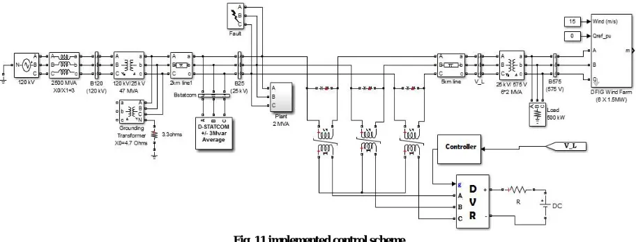
A 3Mvar DSTATCOM and a DVR is used to control the problem of Delayed voltage recovery and minimize the electromechanical oscillations in the DFIG. Implemented control scheme is as shown in fig.11 Specifications of these FACTS devices are as given below
Specifications of DSTATCOM
Coupling transformer of rating 25kV/1.25kV, it couples PWM-inverter of D-STSTCOM8with line to be compensated
A PWM Voltage-Sourced Inverter with switching frequency 1.68 kHz
LC damped filters with L=0.8mH and C=100µF is connected at the inverter output and the Q-factor of this filter is 40
A 10000-µF Capacitor which acts as a DC voltage-source for the inverter
Anti-aliasing-filters which provides acquisition of voltage and current
Specifications of DVR
Three single phase 25kV/360V transformer units which acts as boosting transformer
A IGBT based Voltage Source Inverter which is used to convert DC power stored into AC output
A 700V battery unit to provide power to device Passive Filter unit with R=1Ω and C= 100µF
A controller unit which uses Fourier analysis to generate switching signals for IGBT’s of VSI
Results for proposed control scheme are as shown below.
Fig. 11 implemented control scheme
ISSN(Online): 2319-8753 ISSN (Print): 2347-6710
I
nternational
J
ournal of
I
nnovative
R
esearch in
S
cience,
E
ngineering and
T
echnology
(An ISO 3297: 2007 Certified Organization)
Website: www.ijirset.com
Vol. 6, Issue 8, August 2017
Fig. 12 Electromagnetic torque of the motor after mitigation Fig. 13 Motor Speed after mitigation of FIDVR
of FIDVR
In Fig. 14 it can be seen that excessive active power consumed seen in previous case has been reduced also in Fig. 15 it can be seen that reactive power consumption at bus B25 is almost at 0 Mvar due to injection of reactive power by DSTATCOM
Fig. 14 Consumption of active power at bus B25 after Fig. 15 Consumption of Reactive power at bus B25 after
mitigation of FIDVR mitigation of FIDVR
ISSN(Online): 2319-8753 ISSN (Print): 2347-6710
I
nternational
J
ournal of
I
nnovative
R
esearch in
S
cience,
E
ngineering and
T
echnology
(An ISO 3297: 2007 Certified Organization)
Website: www.ijirset.com
Vol. 6, Issue 8, August 2017
In Fig. 17 it can see that speed of DFIG has negligible electro mechanical oscillations also their amplitude is very less as compared with Fig. 10 in case1. It can be seen that in case1 oscillations in DFIG lasts more than 5 seconds but in case2 DFIG speed is recovered almost instantly as fault is removed.
V.CONCLUSION
In first part of this paper simulation of the FIDVR problem is carried out in a typical wind farm and its effect on performance of DFIG are analysed. It is found that negative sequence component of electromagnetic torque directly affects the speed of DFIG. This negative-sequence torque cause motor to take longer time to reach steady state, consuming extra active and reactive power and eventually causing delayed in voltage recovery of bus where induction motor is connected which results in oscillation in speed of DFIG.
In second part of simulation a DSTATCOM and DVR is used in the system which compensates for the extra reactive power consumed by the motor and also eliminates the voltage dip and imbalance in bus voltage resulting motor to reach its steady state quickly. This quick recovery of motor reduces the FIDVR problem also helps to eliminate the oscillations in DFIG speed.
VI.APPENDIX
Table 1 Parameters of Induction Motor in 2MVA Plant.
Parameter Description Value
Pmotor Nominal power of motor 1.68MW
Rs Stator Resistance5 0.0092 p.u.
L1s Stator Leakage Reactance 0.0711 p.u.
Rr’ Rotor-Resistance 0.007 p.u.
L1r’ Rotor leakage reactance 0.0717 p.u.
Lm Mutual Inductance 4.12 p.u.
Hm Inertial constant of motor 0.1 seconds
P Motor pole pairs 2
Vn (rms) Voltage (L-L) 2300 V
F Frequency 60 Hz
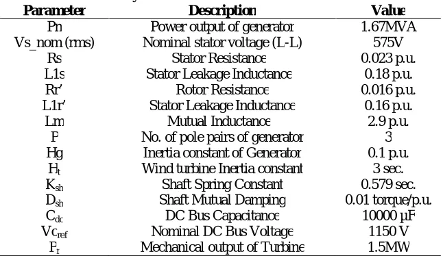
Table 2 System Parameters of DFIG’s in win farm.
Parameter Description Value
Pn Power output of generator 1.67MVA
Vs_nom (rms) Nominal stator voltage (L-L) 575V
Rs Stator Resistance1 0.023 p.u.
L1s Stator Leakage Inductance1 0.18 p.u.
Rr’ Rotor Resistance 0.016 p.u.
L1r’ Stator Leakage Inductance 0.16 p.u.
Lm Mutual Inductance1 2.9 p.u.
P No. of pole pairs of generator 3
Hg Inertia constant of Generator 0.1 p.u. Ht Wind turbine Inertia constant 3 sec.
Ksh Shaft Spring Constant 0.579 sec.
Dsh Shaft Mutual Damping 0.01 torque/p.u.
Cdc DC Bus Capacitance 10000 µF
Vcref Nominal DC Bus Voltage 1150 V
ISSN(Online): 2319-8753 ISSN (Print): 2347-6710
I
nternational
J
ournal of
I
nnovative
R
esearch in
S
cience,
E
ngineering and
T
echnology
(An ISO 3297: 2007 Certified Organization)
Website: www.ijirset.com
Vol. 6, Issue 8, August 2017
REFERENCES
[1] “Analysis of the Influence of the FIDVR Problem in the Operation of a DFIG under Unbalanced Conditions”, 2016 IEEE PES Transmission & Distribution Conference and Exposition - Latin America (PES T&D-LA). Morelia, Mexico.
[2] Rafael C. Borges, Rodrigo A. Ramos and Murilo E. C. “A Control Scheme for Mitigation of DFIG Oscillatory Behavior related to FIDVR Problem”, Bento School of Engineering of Sao Carlos University of Sao Paulo (USP) Sao Carlos, Brazil,2016
[3] Richard J. Bravo and David P. “Fault Induced Delayed Voltage Recovery (FIDVR) Model Validation”, Chassin Southern California Edison and Pacific Northwest National Laboratory, 2016 IEEE
[4] Hicham Lhachimi, YoussefEI Kouari, Yassine Sayouti “Control Strategy of DFIG for Wind Energy System in the Grid Connected Mode” IEEE, 2016
[5] Weihong Huang, Kai Sun, “A New Approach to Optimization of Dynamic Reactive Power Sources Addressing FIDVR Issues” Yan Xu Oak Ridge National Laboratory Oak Ridge, TN, USA, 2014 IEEE
[6] N. W. Miller, and M. Shao, "Active control of distribution connected photovoltaic systems for reduction of fault-induced delayed voltage recovery", in CIRED Workshop, 2014, pp. 1-4.
[7] R. J. Bravo, R. Yinger, and P. Arons, "Fault induced delayed voltage recovery (FIDVR) indicators," in T&D Conference and Exposition, 2014 IEEE PES, pp. 1-5.
[8] Risha Dastagir, Mariam Asif “Power Quality Improvement Using A DVR” Presented in IJRDET, ISSN 2347 – 6435,Volume 2, Issue 5, May 2014
[9] Alpesh Mahyavanshi, M. A. Mulla, R. Chudamani “Reactive Power Compensation by Controlling the DSTATCOM” published by IJETAE, ISSN 2250-2459, Volume 2, Issue 11, November 2012
[10] The Gazette of of India, june 26, 2010 (ASADHA 5, 1932), Art III – Sec.4
[11] “A Technical Reference Paper Fault- Induced Delayed Voltage Recovery”, Transmission Issues Subcommittee and System Protection and Control Subcommittee of NERE, 116-390 Village Blvd., Princeton, NJ08540,2009
[12] Daniel Sullivan, Ron pape and Joe birsait, “Managing fault-induced delayed voltage recovery in Metro Atlanta with the Barrow County SVC”, Power system conference and exposition, 10.119/PSCE 2009, 4840225,Seattile, WA, USA
[13] Ismail A. Hamzah, Jamal A. Yasin “Static Var Compensators (SVC) Required to Solve the Problem of Delayed Voltage Recovery Following Faults in the Power System of The Saudi Electricity Company, Western Region (SEC-WR)”, Paper accepted for presentation at 2003 IEEE Bologna PowerTech Conference