Copyright to IJIRSET DOI:10.15680/IJIRSET.2015.0412115 12321
Review On-Design of Load Filter for Medium
Voltage Drive Used in Submersible Pump
Arpit Jain
1, M.R.Bachawad
2P.G. Student, Dept. of Electrical Engineering, Government College Of Engineering, Aurangabad, Maharashtrat,India1 Assistant Professor, Dept. of Electrical Engineering, Government College Of Engineering, Aurangabad, Maharashtra, India2
ABSTRACT: VFD are increasingly used for high-power electrical submersible pump (ESP) wells. Due to long length cable in ESP system harmonics is produced in system due series harmonic resonance occurred so the load filter remains to be a critical component in such applications. The design of load filter with different length of cable and different type of configuration for MVD (medium voltage drive) and two typical configurations for ESP systems is discussed. Three scenarios (no load filter, with an improperly designed load filter, and with the load filter designed using the proposed method) are discussed.
KEYWORDS: Electrical submersible pump (ESP), frequency response characteristics Load filter, medium -voltage drives (MVDs), neutral point-clamped inverter, parallel resonance, series resonance.
I.
I
NTRODUCTIONAs the oil reserves on the mainland have decreased, the oil companies started to extend their oil research area to offshore, thus offshore power systems have become enormously important. However, pumping oil from deep water is facing with different challenges related to the power system components.
A VFD can control the electrical submersible motor to a speed that better produces the well and keeps the ESP within its best efficiency range. VFDs also offer soft motor starting for ESP systems and reduce impact to power grid during the motor start-up [1] now Variable Frequency Drives (VFDs) are widely used in offshore-oil pumping systems[2]-[6]; due to the several advantages they offer to offshore oil pumping systems. Firstly, VFDs are important for motor starting issues. Cross-line starting and reduced voltage starting are traditional ways of motor starting. Neither of these traditional methods offers flexible starting for motors. Especially with cross-line starting, large amount of stress is applied on the motor due to the highest inrush currents as compared to the other methods. However, VFDs offer more flexible starting for motors with a constant volt per hertz method. In this case, voltage and frequency applied to the motor are started from smaller values and increased correspondingly; the ratio between voltage and frequency stays constant. Thus, this soft starting reduces the possibility of drawing sand in and cracks on the shaft. Another advantage of VFDs is being more efficient than throttling control valves in order to adjust the pressure in the oil well. Moreover, the dc bus capacitor allows the system run through during the case of a voltage sagging. However, the systems with VFDs contain some harmonics which cause resonance issues. especially if the system has subsea cables [8]. Depending on system configuration, series or parallel resonances could cause higher harmonic distortions in the system.
Copyright to IJIRSET DOI:10.15680/IJIRSET.2015.0412115 12322
the motor windings. Therefore, the system should be designed properly to reduce the drawbacks of VFDs and umbilical cable.
Much effort has been carried out on how to mitigate the series harmonic resonance in ESP systems by conducting the harmonic analysis and designing load filters at the drive output circuit [2]–[6], [20], [21]. The LC filter is a commonly designed filter type connected directly at the output of the inverter [22]–[26]. In this paper, a load filter design method for MVD applications in ESP systems is proposed, which is suitable for various types of MVDs and with various lengths of cables in ESP systems. Show the basic diagram of system
Fig 1. Load filter applications for MVDs in ESP system
In fig 1. A Load filter is connected in between medium voltage drive and subsea cable system to avoid the harmonics generated due to subsea cable .The load harmonic characteristics and spectra produced at the output of MVDs are investigated based on PWM techniques and carrier/switching frequencies, which will serve as the theoretical foundation for choosing the resonance frequency of the load filter using the proposed design method
II.
M
EDIUM-V
OLTAGEM
ULTILEVELC
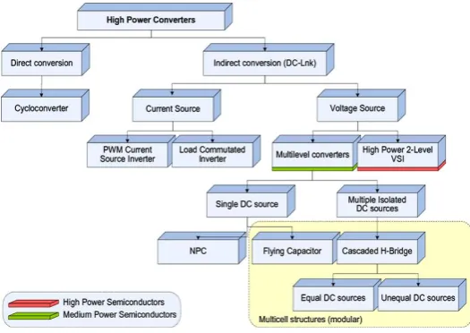
ONVERTERSMedium-voltage (MV) drive found widespread applications in ESP, production plants, and process industries. Only 3% of the currently installed MV motors are controlled by variable-speed drives [7]. The design of controlled MV drives is faced with a number of challenges that relate to the topologies and control of line- and motor-side converters, as well as power Semiconductor switching devices show the classification of multilevel inverters [7].
Fig. 2. Tree diagram different classifications of multilevel inverters
Copyright to IJIRSET DOI:10.15680/IJIRSET.2015.0412115 12323
If a way could be found to produce medium voltage by combining several low-voltage IPWM converters, it should be cost-effective. Such an approach would take advantage of the high manufacturing volume of low-voltage devices, and would yield several other benefits to be described [13].
Copyright to IJIRSET DOI:10.15680/IJIRSET.2015.0412115 12324
Show the cascaded H-bridge inverter is made up of series connected single-phase full-bridge inverters, each with their own isolated dc bus [12].Fig.4shows a configuration for an 18-pulse cascaded H-bridge inverter motor drive system [13]. Each phase has three power modules in Fig. 4. The power module for a cascaded H-bridge inverter drive is a static PWM power converter as shown in Fig.5
III.
A
PPLICATIONS OFS
UBSEAC
ABLES ANDT
ECHNICALC
HALLENGESSubsea cables are very common in the electrical submersible pump (ESP) systems for offshore platforms. Challenges of VFDs in the system combined with long cables may cause serious issues depending on the system configuration. Figure.6 and Figure.7 show two typical configurations for subsea ESP systems.
Fig 6. Configuration 1 [2] Fig 6. Configuration 2 [2]
ESP systems similar to configuration 1, shown in Figure 6, have an advantage of supporting numerous VFD-ESP wells. Another advantage of configuration 1 over configuration 2 is that the cables between VFDs and ESP motors are considerably shorter downhole cables enabling easier motor starting. However, the main problem with configuration1 is the parallel resonance issues. Length of the subsea cable, cable parameters, and VFD type are the factors which affect the parallel resonance their harmonic current spectrums at the drive input are determined based on [2,13] and [2,15]. The parameters of the three types of subsea cables are provided in reference .Certain types of VFDs draw certain dominant harmonic currents; for example 5th harmonic dominates for 6-pulse VFDs, 12-pulse VFD draws 11th harmonic mostly, and etc. When those harmonics coincide with the resonance frequencies of the cables (resonance frequency of cables depend on the cable parameters), the magnitude of those harmonics are amplified, and total harmonic distortion of the line current on the distribution-side of the cable becomes worse than VFD-side of the cable. If the system has 6-pulse VFDs, the 5th harmonic is dominant in the waveforms and it is about 9.6% on the load side and about 88.3% on the distribution side of the subsea cable. The cable creates a resonant circuit for the 5th harmonic, thus the 5th harmonic magnitude is amplified and caused a bigger distortion on the distribution side of the cable if the system is not analyzed carefully, severe effects of parallel resonance in system
Copyright to IJIRSET DOI:10.15680/IJIRSET.2015.0412115 12325
causing difficulty in starting the motor. Another problem with this configuration is that, Series resonance on the load side of the VFD for a subsea ESP installation does exist but can be successfully attenuated using a properly designed load side harmonic filter. This type of resonance was studied extensively for the drive inverter with a long cable motor drive system, also known as voltage reflection [2, 17], [2,18]. Such types of resonance or voltage reflection can be effectively attenuated by using C filter [2, 19], RC filter [18], RLC filter [2,18], [20], and LC filter [2,21], [22]. LC
filters appear to be a commonly used method for the motor drive system harmonic mitigation through long cabling.
IV.
L
OADH
ARMONICSA
NALYSIS ANDM
ITIGATIONThe load harmonic spectrum at the output of the NPC inverter were in[12] and[27].For a three-level NPC inverter, characteristic harmonic bands of the line-to-line voltage are located around the multiple of its carrier frequency fc. The first harmonic band appears around the carrier frequency. The harmonic spectra of the line-to-line voltage for a three-level NPC inverter with carrier frequencies equal to 750 and 1900 Hz are provided[18] and shown in fig.
Fig.8. Harmonic spectra of the voltage at the output of a three level NPC inverter with two carrier frequencies (750 and 1900 Hz) and the
fundamental frequency equal to 50 Hz [18]. (a) Carrier frequency fc = 750 Hz. (b) Carrier frequency fc = 1900 Hz
fig.8(a,b),using a 1900-Hz carrier frequency, the first harmonic band almost spreads to 1000 Hz .To avoid the series resonance excited by load harmonics of the voltage at the inverter output, the overall system peak resonance point should be located at a frequency away from characteristic harmonic frequencies. Therefore the method to design an effective load filter is that the resonance frequency of the load filter itself should be in the range between 750 and 1000 Hz
The resonance frequency of LC load filter can be calculated as follows.
Where,
L and C are the inductance and capacitance of the circuit respectively
The method for design the filter for ESP system with MVD applications is as follows. 1) Find ,the resonant frequency of the load filter using the chosen L and C values .
2) Compare the resonant frequency value from step 1) with the criteria of [750 Hz, 1000 Hz] range.
3) If the value is within range, it is acceptable; otherwise, choose new L and C values, and repeat steps 1) and 2). 4) Simulate the frequency response characteristic of a sample ESP system with and without the load filter connected to verify the design.
Copyright to IJIRSET DOI:10.15680/IJIRSET.2015.0412115 12326
V.
C
ONCLUSIONSince each VFD shows different Harmonic spectrum and frequency response and for each length of cable analysis should be conducted and best solution for the specified length should be selected. Harmonic filter should be designed to avoid series resonance which causes possible voltage spikes on motor terminal voltages.
So the load harmonic analysis always be conducted during the design stage of an ESP system to evaluate the effectiveness of the load filter. By choosing proper inductance and capacitance values of the load filter to make the system resonance frequency shift away from load harmonics The load harmonic characteristics of medium voltage drives are different as compare to low voltage drive and depend on the control methods of the drives.
REFERENCES
1) T. R. Brinner, R. H. McCoy, and T. Kopecky, ―Induction versus permanent-magnet motors for electric submersible pump field and laboratory
comparisons,‖ IEEE Trans. Ind. Appl., vol. 50, no. 1, pp. 174–181, Jan./Feb. 2014.
2) X. Liang, S. O. Faried, and O. Ilochonwu, ―Subsea cable applications in electrical submersible pump systems,‖ IEEE Trans. Ind. Appl., vol. 46,
no. 2, pp. 575–583, Mar./Apr. 2010.
3) R. Pragale and D. D. Shipp, ―Investigation of premature ESP failures an oil field harmonic analysis,‖ in Conf. Rec. 59th IEEE IAS Annu.
Meeting,2012, pp. 1–8.
4) W. Phang, P. Brogan, G. Lightbody, R. Yacamini, and A. Scott, ―Reduction of over voltages on ESP systems,‖ in Proc. 8th Int. Conf.
Harmonics Quality Power, 1998, vol. 2, pp. 970–975.
5) G. Skibinski and S. Breit, ―Line and load friendly drive solutions for long length cable applications in electrical submersible pump
applications,‖ in Conf. Rec. 51st IEEE IAS Annu. Meeting, 2003, pp. 269–278.
6) Metwally and A. Gastli, ―Factors affecting transient over voltages of electric submersible pumps,‖ IEEE Potentials, vol. 25, no. 5, pp. 13–
17,Sep./Oct. 2006.
7) J.C. Read, "The Calculation of Rectifier and Inverter Performance Characteristics," Proceedings of the IEEE, Vol. 92, Part 2, No. 29, pp.
495-509, October 1945.
8) T. R. Brinner, J. D. Atkins, and M. O. Durham, ―Electric submersible pump grounding,‖ IEEE Trans. Ind. Appl., vol. 40, no. 5, pp. 1418–
1426,Sep./Oct. 2004.
9) IEEE Recommended Practices and Requirements for Harmonic Control in Electrical Power Systems, IEEE Std. 519-1992, 1993
10) S. Bell and J. Sung, ―Will your motor insulation survive a new adjustable frequency drive?‖ IEEE Trans. Ind. Appl., vol. 33, no. 5, pp. 1307–
1311, Sep./Oct. 1997.
11) S. Ul Haq, S. H. Jayaram, and E. A. Cherney, ―Degradation of turn insulation subjected to fast repetitive voltage pulses,‖ in Proc. Elect. Insul.
Conf. Elect. Manuf. Expo, 2005, pp. 163–166.
12) D. Krug, S. Bernet, and S. Dieckerhoff, ―Comparison of state-of-the-art voltage source converter topologies for medium voltage applications,‖
in Conf. Rec. 38th IEEE IAS Annu. Meeting, 2003, vol. 1, pp. 168–175.
13) F. Endrejat and P. Pillay, ―Resonance in medium-voltage multilevel drive systems,‖ IEEE Trans. Ind. Appl., vol. 45, no. 4, pp. 1199–1209,
Jul./Aug. 2009.
14) T. R. Brinner and R. A. Durham, ―Transient-voltage aspects of grounding,‖ IEEE Trans. Ind. Appl., vol. 46, no. 5, pp. 1796–1804,
Sep./Oct. 2010.
15) X. Liang, J. Stevens, and D. Kelly, ―Subsea cable applications in offshore oil field facilities,‖ in Proc. SPE Offshore Europe Oil Gas Conf.
Exhib., Aberdeen, U.K., Sep. 3–6, 2013, pp. 1–12.
16) X.Liang and R. Adedun, ―Load harmonics analysis and mitigation,‖in Proc. IEEE I CPS, Louisville, KY, USA, May 19–25, 2012, pp. 1 8.
17) T. Laczynski and A. Mertens, ―Predictive current controller for inverter fed medium voltage drives with LC filter,‖ in Proc. 7th Int. Power
Electron.Drive Syst., 2007, pp. 1496–1501.
18) Y. Shakweh and P. Aufleger, ―Multi-megawatt medium voltage, PWM, voltage source sine-wave-output converter for industrial drive
applications,‖ in Proc. 7th Int. Conf. Power Electron. Variable Speed Drives,1998, pp. 632–637.
19) H. Akagi and S. Tamura, ―A passive EM1 filter for an adjustable-speed motor driven by a 400-V three-level diode-clamped inverter,‖ in Proc.
35th Annu. IEEE Power Electron. Spec. Conf., 2004, pp. 86–93.
20) Z. Haitao, Z. Zhengming, Y. Liqiang, and B. Hua, ―Simulation, test and analysis of three-phase short-circuit braking in IGCT-based MV
adjustable speed drive systems,‖ in Proc. 8th Int. Conf. Elect. Mach. Syst., 2005, pp. 1437–1441.
21) H. Abu-Rub, J. Holtz, J. Rodriguez, and G. Baoming, ―Medium-voltage multilevel converters—State of the art, challenges, and requirements
in industrial applications,‖ IEEE Trans. Ind. Electron., vol. 57, no. 8, pp. 2581– 2596, Aug. 2010.
22) H. du Toit Mouton, ―Natural balancing of three-level neutral-point clamped PWM inverters,‖ IEEE Trans. Ind. Electron., vol. 49, no. 5,
pp. 1017–1025, Oct. 2002.
23) A. Nabae, I. Takahashi, and H. Akagi, ―A new neutral-point-clamped PWM inverter,‖ IEEE Trans. Ind. Appl., vol. 1A-17, no. 5, pp.
518– 523, Sep./Oct. 1981.
24) J. Patrick Lyons et al., ―High power motor drive converter system and modulation control,‖ U.S. Patent 5 910 892, Jun. 8, 1999.
25) T. A. Meynard,M. Fadel, and N. Aouda, ―Modeling of multilevel converters,‖ IEEE Trans. Ind. Electron., vol. 44, no. 3, pp. 356–364
June.1997.
26) B. P. McGrath and D. G. Holmes, ―A comparison of multicarrier PWM strategies for cascaded and neutral point clamped multilevel
Copyright to IJIRSET DOI:10.15680/IJIRSET.2015.0412115 12327
27) P. W. Hammond, ―A new approach to enhance power quality for medium voltage ac drives,‖ IEEE Trans. Ind. Appl., vol. 33, no. 1, pp. 202–