Simulation Analysis of Maximum power Point Tracking in
Grid connected Solar Photovoltaic System
P.Murugan
1,
R. Sathish Kumar
2 1PG Scholar, Electrical and Electronics Engineering, Anna University Regional office Madurai
2
Assistant Professor, Electrical and Electronics Engineering, Anna University Regional office Madurai
Abstract: This work proposes a method of generation of power in rural areas using photovoltaic energy. In order to utilize energy of photovoltaic to maximum extent MPPT is also incorporated in it. The MPPT tracks the optimal point at which maximum energy can be extracted from the panel. For operating the PV at maximum power the conductance matching for the PV panel is done by varying the duty cycle of DC to DC converter connected to it. The inverter used is a double stage where initially the power is regulated using a DC to DC converter and then the DC power is inverted and it is synchronized to grid using the Phase Locked Loop (PLL). The power generated here is single phase power at 230Volts and 50 Hertz, which can be used for domestic applications. The paper gives a brief introduction to methods of MPPT and the designing methodology of DC to DC converter and the application of PLL in grid synchronization. The proposed work is simulated using MATLAB SIMULINK.
.
Keywords: photovoltaic; maximum power point tracking; PLL; boost converter; incremental inductance.
1
. Introduction
The power sector is now facing great crises in power, where the difference between the demand and generation is very high. This situation primarily causes intermittent power in rural areas. The rural areas are the primary effectors for such power situations. The development in green energy is also concentrated mostly in heavily industrialised areas. This will not improve the situation of power cuts in rural areas. The load that is utilised by major rual ares will be single phase energy and it will be in the order of Kilowatts. If the generation of such power is done with the help of green technologies, it will be more helpful for the livelihood of rural regions. of all the green powers available the wind and PV are most common methods. The energy system considered here is PV based energy system. The power extracted from the Photovoltaic system is DC as the power that is used for domestic purpose AC power. So power has to be converted back to AC power for better utilisation. The power that is generated has to be synchronised with grid so that you can utilize the existing distributed network.
MPP is a point which satisfies the maximum power transfer theorem. The optimum power point can be tracked with various methods. Some of the
most common methods[1],[2],[3] used are Perturb and observe (P&O), Incremental conductance[4], fuzzy logic[5] and neural network based[6] . P&O is the most commonly used controlling process mostly because of its simple algorithm and easy implementation. It works on principle that the rate of change of power will be minimum around MPP. It samples the present value of voltage, power and compares it with the previous value, the point at which the minimum rate of power change is observed the perturbation is congested. P&O has disadvantage of oscillation around the MPP. Incremental conductance is one more most commonly used algorithm which is based on the truth that the slope of the P-V curve will approaching zero as system reaches the MPP. In order to find the operating point the change in current and change of voltage are considered. It provides the better MPPT even in rapidly varying atmospheric conditions. The oscillations are also less compared to P&O. The limitation of this is system is in choosing the incremental step size. Low value step size takes the more response time and high step sizes leads to oscillations. In the above two methods have the basic disadvantage of fixed step size.
construction, ease of application, low cost and robust performance in a wide range of operating conditions. The selection of a PID as an MPPT controller satisfies most of the above aspects. The design of such a PID controller which requires the determination of three parameters: proportional gain, integral time constant and derivative time constant is discussed in brief in this paper.
The major importance of this paper lies in designing the PLL which is used for synchronizing the power that is generated and inverted with the existing grid. The power that is generated by the PV can be inverted to desired value by controlling the fate pulses. The PLL controls the switching sequence of the gates and produces required synchronization.
II.
Methodology
The major things that have to be considered in development of grid synchronised PV generation are PV module, DC to DC converter, MPPT controller and PLL for synchronising generated single phase with the grid.
A. PV modelling:
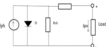
The PV module characteristic is a non linear characteristic which depends on the reverse saturation current of the diode in parallel to the photo current source. The photon current is produced because of the photovoltaic action [7],[8]. The equivalent circuit of a PV cell is as depicted in Figure 1. The current source Iph represents the cell photocurrent. The series and shunt resistances are represented as Rs and Rsh. The PV cells are grouped in larger units called PV modules which are further interconnected in a parallel-series configuration to form PV arraysThe current source Iph represents the cell photocurrent. Rsh and Rs are the intrinsic shunt and series resistances of the cell, respectively. Usually the value of Rsh is very large and that of Rs is very small, hence they may be neglected to simplify the analysis. The PV cells are grouped in larger units called PV modules which are further interconnected in a parallel-series configuration to form PV arrays.
Fig 1. PV Cell Modelled as Diode Circuit
The photovoltaic panel can be modeled mathematically as given in equations (1) - (4)
Module photo-current:
Iph= [ Iscr+ ki (T − 298)]*λ /1000 (1)
Where Iphis the photocurrent in (A) which is the light-generated current at the nominal condition (25℃ and 1000W/m2), Ki is the short-circuit current/temperature coefficient Iscr at (0.0017A/K), T is the actual temperature in K, λ is the irradiation on the device surface, and 1000W/m2 is the nominal irradiation.
Modules reverse saturation current Irs:
Irs= Irs/[exp(q voc/NskAT)−1] (2)
The module saturation current IOvaries with the cell temperature, which is given by:
IO=Irs�TTr� 3
exp[q∗Ego BK {
1 Tr−
1
T}] (3) Where IO is the diode saturation current (A). The
basic equation that describes the current output of the photovoltaic (PV) module IPV of the single-diode model is as given in equation.
Thus,
IPV=NP∗IPH−NP∗IO[exp {q∗�VPV+IPVRs�NsAKT }-1] (4)
Where K is the Boltzmann constant (1.38 x 10⁻²³ JK−1), q is the electronic charge (1.602 x 10⁻¹⁹C), T is the cell temperature (K); A is the diode ideality factor, Rsthe series resistance (Ω). Ns is the number of cells connected in series. Np is the number of cells connected in parallel, VPV= Voc.These reference values are generally provided by manufacturers of PV modules for specified operating condition such as STC (Standard Test Conditions) for which the irradiance is 1000 W/m2 and the cell temperature is 25℃. The panel specifications are used to design the simulink module of the required panel. The major factors are the open circuit voltage and the short circuit current.
B. DC TO DC CONVERTER:
MPP. The boost converter is widely used to pinpoint the ultimate point of power of the PV array. Here the boost converter and resistive load are connected in parallel with the PV module. These elements form the power circuit. The boost converter can operate in continuous conduction mode along with discontinuous conduction mode. The mode of conduction depends of the capacity for storage of energy along with the relative timeframe of the switching. The design the boost converter mainly includes the coupling capacitor on the input side, capacitor on the output side of converter and the inductor. The output voltage is depends on the duty cycle and it is adjusted by the maximum power controller. The relation of the output voltage with the input voltage as function of duty cycle is given by
Vo Vi =
1
1−D (5)
V0= average output voltage, Vi=the input vo
C. Proposed MPPT controller design:
1)PID controller:
PID controller as the name indicates is proportional integral and derivative controller. The PID controller acts in such a way that it tries to minimize the error which is given as input to the controller. The continuous PID equation is depends on the Kp , Ki and ,Kd values. In order to calculate the proportional, integral and derivative gains of PID controller, the Zeigler Nicholas method is applied.
The algorithm is based on the fact that the slope tangent of the characteristic p–v is zero in MPP, positive on the MPP left side, and negative on the MPP right side. In order to find out the position of the actual operating point in relation to MPP, this algorithm uses the derivate of the conductance di/dv. As the power is equal to the product of current and voltage, the calculation of this slope is given by:
dP dV=
d(VI)
dV = I + V dI
dV= 0 (6)
I V+
dI
dV= 0 (7)
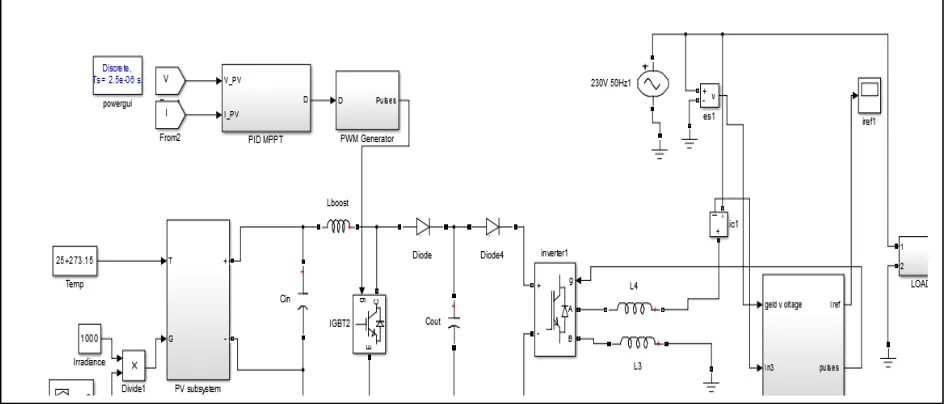
In proposed system the PID controller takes the eq-7 as error signal and tries to reduce it to null value. The PID used in this simulation is used to reduce the error between the slope PV slope to reference value, and controls the switching of boost converter. The Proportional control reduces the offset value, the error reduces the oscillations and the derivative control reduces the time taken to reach the final value. The overall block diagram of the proposed MPPT controller with PV system connected to grid is shown in fig 1:
Fig 2: Block diagram of grid connected PV system
D. Inverter and Phase locked loop
The power that is generated by the photovoltaic is DC it has to converted to AC for utilization in grid integration. For this purpose an universal bridge is used. For proper integration[11],[12],[13],[14] with grid the gate pulses are controlled with the help of Phase LOaked Loop (PLL)
Phase locked loop (PLL) is used to track the fundamental grid voltage even in severe harmonic conditions. We can consider PLL as a higher order band pass filter with a zero phase distortion. The PLL used here considers the parks transformation. This is used to find the phase error detection. The parks transformation is used here to detect the phase error. Once the phase error is detected it has to reduced to zero with the help of PI controller. The optimal working of PLL lies in deciding The values of Kp and Ki. The PLL used here is based on delaying the fundamental wave and finding phase.
III
.
Simulation and results:
To test the model the PV model was designed along with the PID MPPT controller. The PV input given to DC C converter and further to an inverter. The simulation is run for 0.5 sec. The grid was simulated for 230V AC RMS voltage, and the synchronization was done with the help of PLL.
The inverter voltage and current are important here for analysis and validation of designed model. Hence the results comprised of inverter current and voltage. The basic simulation is was shown in fig 3
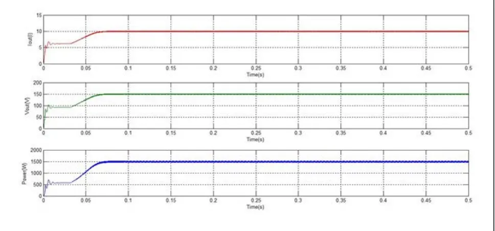
Fig 4: Inverter voltage and current waveforms
A fig.4 show the voltage and current output of inverter, the voltage of 230V RMS can be seen clearly which indicates that it can be used for general residential applications and frequency was nominal 50 Hertz allowing it synchronize to grid easily.
The above result shows the converter output current , voltage and power which shows that the power output of the converter is at its maximum because of the implemented MPPT .
IV
Conclusion:
As renewable energy system has become widespread, PV systems are found to be easy solution for residential applications and low power generation. Modeling of accurate PV system has been a challenge. The model is designed based on the required specifications and from standard data sheets. For this thesis MPPT is implemented using boost converter. In this paper comprehensive simulink PV model was designed, MPPT method coupled with DC/DC converter was simulated, single phase PLL based grid grid connected inverter was designed. The obtained results suit the domestic application of a rural area where energy requirement will be in kilowatts. The generated can utilize existing distribution system as the voltage output is synchronized with grid.
References
1. Esram T, Chapman PL. Comparison of photovoltaic
array maximum power point tracking techniques. IEEE Transactions on Energy Conversion 2007;22:439-49
2. Azevedo, G.M.S., Cavalcanti, M.C., Oliveira, K.C.,
Neves, F.A.S. and Lins, Z.D., “Evaluation of maximum power point tracking methods for grid connected photovoltaic systems,” Conference on Power
3. Electronics Specialists, 2008. PESC 2008. IEEE ,
August 2008, pp. 1456 - 1462.
4. Yi-Hua Liu, Chun-Liu, Jia-Wei Huang, Jing –Hsiau
Chen(2013) Neural-network-based maximum power point tracking methods for photovoltaic systems operating under fast changing environments: Science Direct on solar energy 89 Pg:42-53:
5. Trishan Esram, Patrick L. Chapman, (2007) IEEE
Comparison of Photovoltaic Array Maximum Power Point Tracking Techniques ieee transactions on energy conversion, vol. 22, no. 2, june 2007 pg 439-449
6. A.Vijayakumari, A.T.Devarjan, N.Devarajan
(2012)Design and development of a model-based hardware simulator for photovoltaic array Science Direct on Electrical power and energy systems 43,pg 40-46
7. K.Punitha, D.Devaraj, S.Sakthivel (2012) development
and analysis of adaptive fuzzy controllers for photovoltaic system under varying atmospheric and partial shading condition, science direct on applied soft computing 13,4320-4332;
8. T. Huan-Liang, C.-S. Tu, and Y.-J. Su, “Development
of generalized photovoltaic model using matlab/simulink,” proceedings of the World Congress on Engineering and Computer Science, San Francisco, CA, 2008
9. K. Kurokawa, S. Wakamatsu, Photovoltaic system
design guidebook, Ohmsha, Ltd., ISBN 4-274- 94065-9, 1994.
10. Timothy L. Skvarenina, “The Power Electronics
Handbook, Industrial electronics series”, CRC Press, 2002
11. Ortiz-Rivera, E.I., “Maximum power point tracking
using the optimal duty ratio for DC-DC converters and Load matching in photovoltaic application,” Applied Power Electronics Conference and Exposition, 2008. APEC 2008. Twenty-Third Annual IEEE , May 2008, pp. 987 - 991.
12. Kjaer, S.B., Pedersen, J.K. and Blaabjerg, F., “A
Review of single-phase grid connected inverters for photovoltaic modules,” Industry Applications, IEEE Transactions , vol. 41, September 2005, pp.1292-1306.
13. D. Rajapakse and D. Muthumuni, "Simulation Tools for
Photovoltaic System Grid Integration Studies," IEEE Electrical Power and Energy Conference, EPEC, 2009.
14. K.M.Tsang, W.L.Chan(2013) Model based rapid
maximum power point tracking for photovoltaic systems: Science Direct on Energy Conversion and Manangement 70, Pg :83-89
15. M. Yamaguchi, K. Kawarabayashi, T. Takuma, Y.