Performance Evaluation of Routing Protocols
in MANETs
K.V.Sowjanya 1, Dr.G Mahalaxshmi2
M. Tech Research Scholar, Dept. of ECE, Sreenidhi Institute of Science & Technology, Telangana, India1
Professor, Dept. of ECE, Sreenidhi Institute of Science & Technology, Telangana , India2
ABSTRACT: Mobile Ad Hoc Networks (MANET) are networks formed by mobile radio nodes without supporting infrastructure. The mobility of the radios means that the topology of the network is constantly changing. If there is a high density of radios, then the throughput of the network will be reduced because of mutual interference. In order to solve this problem, here introducing a new protocol Directional local Recovery and Dynamic power Management. Our protocol determines the power required to preserve connectivity through the nodes, in order to decrease interference and power consumption, as well as to improve the network throughput.
KEYWORDS: Manets , Dynamic power, Directional local Recovery.
I.INTRODUCTION
Networks which are formed when radio nodes in a region associate themselves into a network without any presence of infrastructure are called Manets[1]. It doesn’t involve any fixed or wiring point. In this method information transfer take place when nodes are within the communicating range if not intermediate nodes are present between source and destination[2].Nodes in MANET are free to travel, and the connection between two nodes is broken when one of them travels out of the transmission range of the other node [1]. If a mobile has many neighboring nodes within range, there is a high likelihood of mutual interference. Adjusting the transmission power to ensure an adequate number of neighboring nodes in range for connectivity purposes, but not so many as to cause significant interference should allow improved performance[3]. This paper describes proposed Directional Local Recovery and Dynamic Power Management (DLRDPM) for ad hoc network. The proposed power management schemes are two directions. First is to balance power consumption during data transfer and secondly to reduce the power consumed in case of a route failure.
II. PROTOCOLS USED AND THEIR WORKING
Dynamic Power Management
The Dynamic Power Management gives a possible solution for balancing energy consumption by the nodes across the entire ad hoc networks. In this way each and every nodes are not excessively burdened, thus avoiding the death of some important nodes and extending the lifetime of the entire network. Considering an ideal ad hoc network, all nodes would participate equally in the relay activity, forwarding packets for other nodes and having their packets forwarded by other nodes in return and so on. But practically this is not the case, because traffic patterns are not distributed evenly across the network thus resulting in diverse power levels at each node. Even if we consider that initially the power level is same among all nodes, depending on the communication session and the topology used the power level at some frequently used nodes would be quite different from the other nodes. The remaining power of the node diminishes so does its transmitting capability Limiting transmission ranges can also partition the network. If each node were to contribute to the ad hoc community according to its residual power then the effects described above can be counter balanced. This is exactly what the proposed Dynamic Power Management (DPM) does, i.e., it adjusts the nodal transmission power proportionally to its remaining power. Assume all nodes can dynamically change its transmission power. It makes use of the following formula,
The terms used from left to right are the transmission power, power spent on initial transmission, residual power and full power. From the above formula shows that a node with larger power capacity can transmit a packet with higher power level. Also nodes with limited resources would not be required to expend much energy. Without the above formula an intermediate node may be used repeatedly and before long its remaining power would be lesser when compared to others. Using the DPM scheme the power among all nodes are dynamically balanced. It dynamically adjusts the transmission power across all the nodes. Compared to static power management, the total power consumed is reduced as each node transmits according to its remaining power. In DPM nodes with less residual power consume less energy than those with more residual power. Thus it helps in avoiding the early death of nodes with less residual power.
The power consumption can be reduced if unnecessary traffic can be reduced or eliminated. The method proposed below is based on the fact that much energy can be saved if localized route recovery is deployed rather than global flooding during the process of route recovery. Before moving into a route failure case let us first understand the general transmission of a data packet between the source and the receiver and the various terms associated with it. In an on demand routing protocol the source node floods the network with RREQ messages when it doesn’t find a suitable route to the destination. A RREQ carries the source identifier (SrcID), destination identifier (DestID), source sequence number (SrcSeqNum), destination sequence number (DestSeqNum), broadcast identifier (BcastID) and time to live (TTL). When an intermediate node receives a RREQ it either forwards or prepares a RREP if there is a path to the destination. Every intermediate node while forwarding the RREQ enters the previous node address as its BcastID. If a RREQ is received multiple times which is indicated by the BcastID-SrcID pair, duplicate copies are discarded. As shown in Figure 1.1
Figure 2.1: Transmission of RREQ from source to the destination
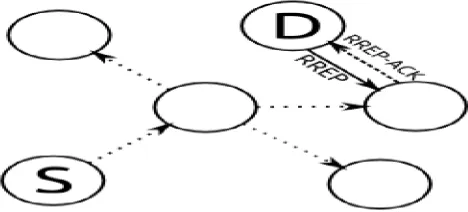
When the RREQ reaches the destined node a RREP packet is sent back to the source node. The link between two nodes may be unidirectional; hence a flag is set in the RREP to indicate that the connection has been acknowledged. As shown in below Figure 2.2
Figure 2.2: RREP to connection has been acknowledged
Directional Local Recovery(DLR)
In DLR the flooding issued by the node detecting the broken link has a directional property. Note that the ability of directional transmission is not assumed at each node. The directional concept is embedded in the route recovery by using the number of hops the candidate nodes share with the primary path. This method can be broadly classified into the following steps:
From the node detecting the broken link the nodes that have to be traversed by RREQ can be referred as the candidate nodes cluster. Candidate nodes are used to recover the disconnected path using the reconnected routing information. This scheme produces better results with less control packets and with faster path recovery time. The cluster can be formed by overhearing the RREP messages from the destination. The neighbor of a node in the primary path from source to destination also overhears the RREP from the destination. A flag (candidate flag) is set by each neighbor to indicate if a node is a candidate node for a future alternative path. A candidate node in addition shares the same number of hops to the destination as the associated member node in the primary path. An example is illustrated below show in figure 1.4
Figure 2.3: A candidate node in addition shares the same number of hops to the destination
The dashed lines depict overhearing and the solid lines RREP message. From the above figure we observe that when the destination sends the RREP to node A, nodes A’ and A” overhear the RREP and the number of hops from the destination. Next when node A relays the RREP to node B, node B’ overhear the number of hops and RREP of node A. Node A” also overhears the RREP of node A, but since A” already has the number of hops of previous node in the primary path it discards this 2nd RREP. In the similar way we can say nodes A’ and A” are associated with the destination node, node B’ associated with node A, C’ and C” associated with node B and so on. Consequently as the primary path is set the cluster of candidate nodes are as shown the figure 2.5
Figure 2.4: The route connecting the source to the destination
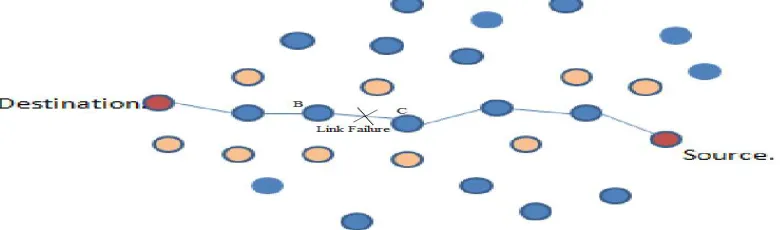
The route connecting the source to the destination is the primary path and the number of hops here are six. The nodes in orange are the cluster of candidate nodes.
Step 2: Repairing a broken link
Assume that as shown in figure 1.5 a broken link has been detected between two nodes B and C. Node C detects the broken link and tries to repair by broadcasting RREQ message to its neighbors. Only if the following conditions are fulfilled will the neighboring nodes receive the RREQ.
1) The candidate flag of the neighbor node must be set.
2) The number of hops of the node receiving RREQ must not be less than the number of hops of the node sending RREQ.
Figure 2.5: Final Route Source to Destination
Hence compared to ERS or QL unnecessary flooding can be expected to be reduced by using DLR. The fact that overhearing itself requires additional energy is acknowledged. With further investigation we can determine accurately how much beneficial the approach is in achieving the desired goal.
PERFORMANCE METRICS
The following performance metrics are used to evaluate the proposed DLRDPM protocol with existing DPM and AODV protocols.
1. Packet Delivery Ratio (PDR): It is the ratio between the numbers of packets received successfully to the total number of packets transmitted. It is given by
Nrj = number of packets received at each destination j and
Nsi = packets transmitted through each source i.
2. Average end-to-end delay (E2E): It is the average time taken by the data packets from source to the destination across a MANET. It includes all possible delays caused by buffering during route discovery latency, queuing at the interface queue and retransmission delays at the MAC propagation and transfer times.
Trij = packet received time of jth packet of node i
Tsj = packet sending time of packet j for node i and
n = total number of packets sent or received at node i.
3. Control overhead: The control overhead is defined as the total number of routing control packets normalized by the total number of received data packets.
Where Nprj = Normalized packets received at each destination j and
Nri = Number of data packets received at each ith node.
4. Throughput (Tp): It is the number of packets successfully received by the receiver per unit time.
Where Nrj = number of packets received at each destination j and t = unit time.
Where EC j =energy consumed at each destination j.
III. RESULTS
The proposed DLRDPM protocol evaluated using NS 2. The performance of DLRDPM protocol evaluate by varying no of nodes, node speed and no of connections using ns 2 (network simulator). The simulation results are compared with AODV protocol based on the performance parameters remaining energy, energy consumption, end-to-end delay and packet delivery ratio.
1. Protocol Used AODV,DPM, DLRDPM
No of nodes 10,20,30,40,50
2. Simulation Time 100 sec
3. Traffic Class Constant Bit Rate
4. MAC IEEE 802.11
5. Mobility Model Random Way Point
6. Speed 5,10, 15, 20 m/s
8. Initial Energy 10 J
9. Area 1000x1000
Table 3.1: Simulation Scenario
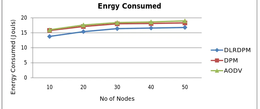
Figure below shows the total energy consumed for the three methods using the simulation scenario tabulated above.
Figure3.2 : Energy consumed Vs No of connections
0 5 10 15 20
10 20 30 40 50
E
n
e
rg
y
C
o
n
s
u
m
e
d
(J
o
u
ls
)
No of Nodes
Enrgy Consumed
DLRDPM
DPM
The total energy consumed using the DPM scheme is better when compared to the energy consumed with the original AODV. The total energy saving increases as the number of nodes increases because more number of mobile nodes is engaged in the routing process. However the total energy consumed when DLRDPM is better when compared to the other two. The reason is that DPM scheme can be used to save more energy and DLR scheme helps reduce the amount of traffic in the network. Hence both when used together gives substantial energy saving.
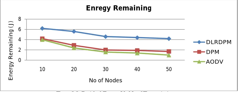
Figure3.3: Residual Energy Vs No of Transmissions
The figure 3.3 observes that remaining energy is decrease with increases no of connections. The DLRDPM have higher remaining energy compared with DPM and AODV protocol. DLRDPM consume less power because of it reduce transmission power.The number of dead nodes over time is an important metric to measure the energy management scheme. Live nodes are able to acquire Energy Efficient link whereas dead nodes are static. The death of a node must be delayed at each monitoring time in a good and fair energy management.
Figure 3.4 : Average end to end delay Vs No of connections
The delay occurs in transmission of CBR packet from client to the server can be termed as the end to end delay. For CBR packet the delay can occur due to number of reasons such as network layer queue, MAC layer delay, transmission delay and propagation delay. In the above figure we observe that AODV with DPM is larger than the original AODV because DPM is employed at MAC layer. The underlying AODV protocol tends to select longer path, hence AODV with DLR and DPM is very close to that of the original AODV.
0 2 4 6 8
10 20 30 40 50
E n e rg y R e m a in in g ( J )
No of Nodes
Enregy Remaining
DLRDPM DPM AODV 0 0.5 1 1.5 2 2.5 310 20 30 40 50
A v e ra g e e n d to e n d D e la y (S e c )
No of Nodes
Average End to End Delay
DLRDPM
DPM
Figure 3.5 : PDR Vs No of Transmissions
The performance of DLRDPM protocol is better when compared to AODV and DPM protocols, conversely as the number of connections varied. The packet delivery ratio reduces with increasing packet drop when no of connection increases, the DLRDPM given better results to increases no connections when compare with DPM and AODV protocol.
IV. CONCLUSION
The proposed DLRDPM are implemented for energy consumption in this thesis. AODV is used as the underlying protocol in each of these methods. The performance evaluation has been carried out using the ns-2 network simulator.Performance analysis shows that the extended methods of AODV when compared with original AODV reduced energy consumption. A DLRDPM and DPM method not only help in reducing the energy consumed but also reduces the number of dead nodes which plays a crucial role in network balancing. The end to end delay has also been measured. The simulation results clearly show how energy can be managed and balanced using the DLRDPM and DPM methods. DPM scheme effectively helps in energy balancing. The performance of DLR alone is not as impressive as DPM, because in order to repair a potential network failure all mobile nodes have to turn their radio on and overhear the traffic. However when DPM and DLR schemes are employed together the performance has been better in all cases, as shown in the analysis.
REFERENCES
[1] I. Chlamtac, M. Conti, and J. J.-N. Liu, “Mobile ad hoc networking: imperatives and challenges,” Ad Hoc Networks, vol. 1, no. 1, pp. 13–64, 2003.
[2] A. Boukerche, B. Turgut, N. Aydin, M. Ahmad, L. B¨ol¨oni, and D. Turgut, “Routing protocols in ad hoc networks: a survey,” Computer Networks, vol. 55, no. 13, pp. 3032–3080, September 2011.
[3] L. Kleinrock and J. Silvester, “Optimum transmission radii for packet radio networks or why six is a magic number,” in Conference Record, National Telecommunications Conference, Birmingham, Alabama, December
1978, pp. 431–435.
[4] E. M. Royer, P. M. M. smith Y, and L. E. M. Y, “An analysis of the optimum node density for ad hoc mobile networks,” in In Proceedings of the IEEE International Conference on Communications, 2001, pp. 857–861.
[5] J. Gomez, A. T. Campbell, M. Naghshineh, and C. Bisdikian, “Paro: supporting dynamic power controlled routing in wireless ad hoc networks,” Wirel. Netw., vol. 9, no. 5, pp. 443–460, Sep. 2003.
[6] A. M. Bamhdi and P. J. King, “Dynamic-power aodv routing protocol based on node density,” in Mobile and Wireless Networking (iCOST), 2012 International Conference on Selected Topics in, 2012, pp. 95–100.
[7] M. K. Marina and S. R. Das, “Ad hoc on-demand multipath distance vector routing,” SIGMOBILE Mob. Comput. Commun. Rev., vol. 6, no. 3, pp. 92–93, Jun. 2002. [Online]. Available: http://doi.acm.org/10.1145/581291.581305
[8] A. M. Bamhdi, P. J. King, and I. S. Ibrahim, “Impact of high density and high speed on aodv and dsr routing protocols.”
[9] C. E. Perkins and E. M. Royer, “Ad-hoc on-demand distance vector routing,” in IEEE WORKSHOP ON MOBILE COMPUTING SYSTEMS AND APPLICATIONS, 1999, pp. 90–100.
[10] (2013) Mobile Ad Hoc Networks MANET. [Online]. Available: http: //www.ietf.org/html.charters/manet-charter.html [11] (2013) The Network Simulator NS-2. [Online]. Available: http://www.isi.edu/nsnam/ns
0 20 40 60 80
10 20 30 40 50
P
ac
ke
t
D
el
ive
ry
R
at
io
No of nodes
Packet Delivery Ratio
DLRDPM
DPM