Available online:
https://edupediapublications.org/journals/index.php/IJR/
P a g e | 2179Optimization of Rotor Hub for Different Materials Using
Ansys Software
1
g.Karthik Chandan,
2s. Mohan Kumar,
3basawaraj S Hasu
1
M.Tech student,
2Assistant professor,
3Assistant professor. Department of Mechanical
Engineering, Avn Institute of Engineering and Technology, Hyd, T.S
ABSTRACT
The rotor system in the helicopter generates lift. The rotor system has three parts. They are mast, hub and rotor blades. A metal shaft extends upwards from the helicopter is called mast. The mast is a hollow cylindrical shaft driven by transmission. The rotor blades are attached to the mast by means of the hub. The hub is the attachment point of the mast and rotor blades. Different methods are used for attachment of the blades to the hub. Based on the attachment method used, the rotor systems are classified.
When rotor spins, control system sends inputs to blades and blade responds to control the helicopter. The center of lift on the whole rotor system moves in response to these inputs to effect pitch, roll, and upward motion.The hub should possess high strength because during flight, the blade weight and aerodynamic forces due to rotational speeds was carried by hub. The strength of the hub should be calculated. This project involves modeling of the rotor hub using NX-CAD software and analyzed the rotor hub using ANSYS software. The rotor hub is analyzed for static analysis using different materials.
INTRODUCTION
Helicopters are in many sizes and shapes, but most share the same major components. These components include a cabin where the payload and crew are carried; an airframe, which houses the various components, or where components are attached; a power plant or engine; and a transmission, which, among other things, takes the power from the engine and transmits it to the main rotor, which provides the aerodynamic forces that make the helicopter fly. Then, to keep the helicopter from turning due to torque, there must be some type of anti torque system. Finally there is the landing gear, which could be skids, wheels, skis, or floats. This chapter is an introduction to these components.
The helicopter's wings are called Main Rotor Blades. The shape and the angle of the blades move through the air will determine how much Lift force is created. After the helicopter lifted off the ground, the pilot can tilt the blades, causing the helicopter to tip forward or backward or sideward.
Basically the wings of the airplane create a lift force when they move through the air. As we known, during flight, there are four forces acting on the helicopter or airplane and those are LIFT, DRAG, THRUST, and WEIGHT. In order to make the wings to move through the air, of course, the plane itself has to move. A helicopter works by having its wings move through the air while the body stays still. The main rotor system of the helicopter was shown in the below figure.
METHODOLOGY
The methodology followed in my project is as follows:
Rotor hub of helicopter is modeled in NX-CAD software.
By using parasolid format, the 3d model was imported to ANSYS software.
International Journal of Research
Available at https://edupediapublications.org/journalse-ISSN: 2348-6848 p-ISSN: 2348-795X Volume 04 Issue 09
August 2017
Available online:
https://edupediapublications.org/journals/index.php/IJR/
P a g e | 2180From static analysis, deflections and stresses of rotor hub were plotted.
Different materials are used to analyze the rotor hub in static analysis. The materials are aluminum alloy, steel, Eglass/Epoxy and Carbon/Epoxy materials.
From analysis results, best material is proposed.
3D MODELLING OF HELICOPTER ROTOR HUB
Fig shows the isometric view of helicopter rotor hub
STATIC ANALYSIS OF HELICOPTER ROTOR HUB FOR STEEL MATERIAL
Objective:
Objective of this analysis is to check the High stressed locations and deflections on the Helicopter rotor Hubfor the applied loads.
Fig. shows infinite model of the Helicopter rotor Hub
Steel, High Strength Alloy ASTM A-514 Mechanical Properties:
Young’s modulus = 210GPa Yield Strength = 690 MPa Tensile Strength = 760 MPa
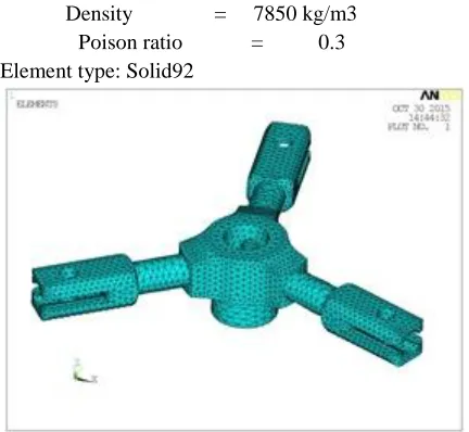
Density = 7850 kg/m3 Poison ratio = 0.3 Element type: Solid92
Fig. showsmeshed model of the Helicopter rotor Hub
Boundary conditions:
All Dof is given to location of the rotating shaft.
The rotor hub is subjected to load of weight of the rotor blade.
A load due to Gravity and Angular velocity is applied on Helicopter rotor Hub due to rotation of hub.
Fig. shows boundary conditions of static analysis
Available online:
https://edupediapublications.org/journals/index.php/IJR/
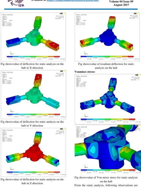
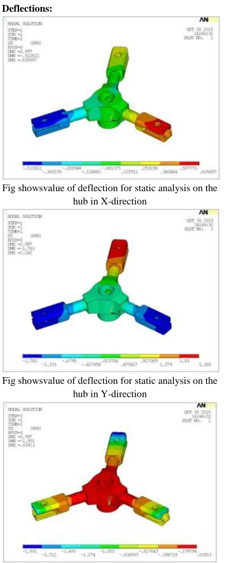
P a g e | 2181Fig showsvalue of deflection for static analysis on the hub in X-direction
Fig showsvalue of deflection for static analysis on the hub in Y-direction
Fig showsvalue of deflection for static analysis on the hub in Z-direction
Fig showsvalue of resultant deflection for static analysis on the hub
Vonmises stress:
Fig showsvalue of Von mises stress for static analysis on the hub
International Journal of Research
Available at https://edupediapublications.org/journalse-ISSN: 2348-6848 p-ISSN: 2348-795X Volume 04 Issue 09
August 2017
Available online:
https://edupediapublications.org/journals/index.php/IJR/
P a g e | 2182The resultant deflection observed on the hub is 0.107mm.
The total von mises stress of 132MPa was observed on the rotor hub as shown in the above figure. The rotor hub has stress of about 19.1% with compare to yield strength of material used. The steel material has yield strength of 690MPa.
Factor of safety = 690/132 =5.2
According to the VonMises Stress Theory, the VonMises stress of Helicopter rotor Hub is less than the yield strength of the material. Hence the design of Helicopter rotor Hub is safe for the above operating loading conditions.
STATIC ANALYSIS OF HELICOPTER ROTOR HUB FOR ALUMINIUM ALLOY MATERIAL Mechanical Properties of Aluminum alloy2014-T6:
Young’s modulus = 72GPa Yield Strength = 414 MPa Tensile Strength = 483 MPa Density = 2800 kg/m3
Fig shows the meshed model of the Helicopter rotor Hub
Boundary conditions:
All Dof is given to location of the rotating shaft.
The rotor hub is subjected to load of weight of the rotor blade.
A load due to Gravity and Angular velocity is applied on Helicopter rotor Hub due to rotation of hub.
Fig. shows boundary conditions of static analysis
Results: Deflections:
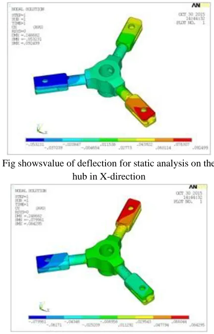
Fig showsvalue of deflection for static analysis on the hub in X-direction
Available online:
https://edupediapublications.org/journals/index.php/IJR/
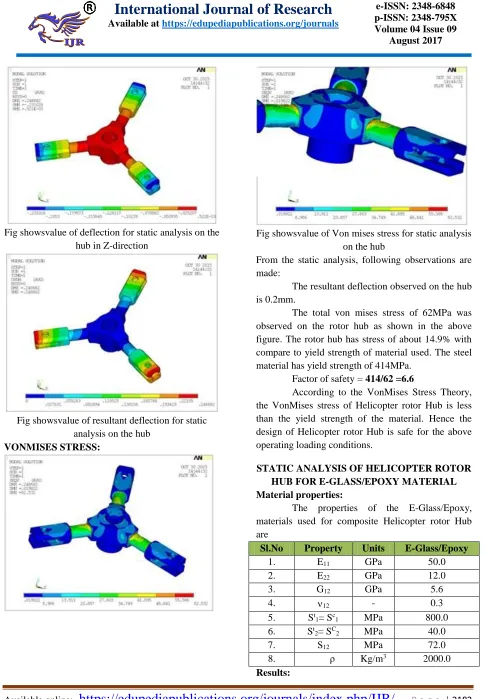
P a g e | 2183Fig showsvalue of deflection for static analysis on the hub in Z-direction
Fig showsvalue of resultant deflection for static analysis on the hub
VONMISES STRESS:
Fig showsvalue of Von mises stress for static analysis on the hub
From the static analysis, following observations are made:
The resultant deflection observed on the hub is 0.2mm.
The total von mises stress of 62MPa was observed on the rotor hub as shown in the above figure. The rotor hub has stress of about 14.9% with compare to yield strength of material used. The steel material has yield strength of 414MPa.
Factor of safety = 414/62 =6.6
According to the VonMises Stress Theory, the VonMises stress of Helicopter rotor Hub is less than the yield strength of the material. Hence the design of Helicopter rotor Hub is safe for the above operating loading conditions.
STATIC ANALYSIS OF HELICOPTER ROTOR HUB FOR E-GLASS/EPOXY MATERIAL Material properties:
The properties of the E-Glass/Epoxy, materials used for composite Helicopter rotor Hub are
Sl.No Property Units E-Glass/Epoxy
1. E11 GPa 50.0
2. E22 GPa 12.0
3. G12 GPa 5.6
4. 12 - 0.3
5. St
1= Sc1 MPa 800.0
6. St
2= SC2 MPa 40.0
7. S12 MPa 72.0
International Journal of Research
Available at https://edupediapublications.org/journalse-ISSN: 2348-6848 p-ISSN: 2348-795X Volume 04 Issue 09
August 2017
Available online:
https://edupediapublications.org/journals/index.php/IJR/
P a g e | 2184Deflections:
Fig showsvalue of deflection for static analysis on the hub in X-direction
Fig showsvalue of deflection for static analysis on the hub in Y-direction
Fig showsvalue of deflection for static analysis on the hub in Z-direction
Fig showsvalue of resultant deflection for static analysis on the hub
Vonmises stress:
Fig showsvalue of von mises stress for static analysis on the hub
From the static analysis, following observations are made:
The resultant deflection observed on the hub is 2.9mm.
The total von mises stress of 360MPa was observed on the rotor hub as shown in the above figure. The rotor hub has stress of about 45% with compare to yield strength of material used. The steel material has yield strength of 800MPa.
Factor of safety = 800/360 =2.2
According to the VonMises Stress Theory, the VonMises stress of Helicopter rotor Hub is less than the yield strength of the material. Hence the design of Helicopter rotor Hub is safe for the above operating loading conditions.
Available online:
https://edupediapublications.org/journals/index.php/IJR/
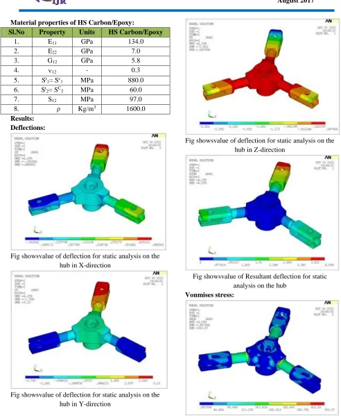
P a g e | 2185Material properties of HS Carbon/Epoxy:
Sl.No Property Units HS Carbon/Epoxy
1. E11 GPa 134.0
2. E22 GPa 7.0
3. G12 GPa 5.8
4. 12 - 0.3
5. St
1= Sc1 MPa 880.0
6. St
2= SC2 MPa 60.0
7. S12 MPa 97.0
8. ρ Kg/m3 1600.0 Results:
Deflections:
Fig showsvalue of deflection for static analysis on the hub in X-direction
Fig showsvalue of deflection for static analysis on the hub in Y-direction
Fig showsvalue of deflection for static analysis on the hub in Z-direction
Fig showsvalue of Resultant deflection for static analysis on the hub
Vonmises stress:
International Journal of Research
Available at https://edupediapublications.org/journalse-ISSN: 2348-6848 p-ISSN: 2348-795X Volume 04 Issue 09
August 2017
Available online:
https://edupediapublications.org/journals/index.php/IJR/
P a g e | 2186From the static analysis, following observations are made:
The resultant deflection observed on the hub is 4.3mm.
The total von mises stress of 364MPa was observed on the rotor hub as shown in the above figure. The rotor hub has stress of about 41.3% with compare to yield strength of material used. The steel material has yield strength of 880MPa.
Factor of safety = 880/364 =2.4
According to the VonMises Stress Theory, the VonMises stress of Helicopter rotor Hub is less than the yield strength of the material. Hence the design of Helicopter rotor Hub is safe for the above operating loading conditions.
RESULTS AND CONCLUSION
Helicopter rotor hub was modeled and analyzed to static analysis. Static analysis was done for different materials i.e. steel alloy, aluminum alloy, Eglass/epoxy material and HS carbon/epoxy material.
Static analysis of helicopter rotor hub with Steel High Strength Alloy material:
From the static analysis,
The resultant deflection observed on the hub is 0.107mm.
The total von mises stress of 132MPa was observed on the rotor hub as shown in the above figure. The rotor hub has stress of about 19.1% with compare to yield strength of material used. The steel material has yield strength of 690MPa.
Factor of safety = 690/132 =5.2
Static analysis of helicopter rotor hub with aluminum alloy material:
From the static analysis,
The resultant deflection observed on the hub is 0.2mm.
The total von mises stress of 62MPa was observed on the rotor hub as shown in the above figure. The rotor hub has stress of about 14.9% with compare to yield strength of material used. The steel material has yield strength of 414MPa.
Factor of safety = 414/62 =6.6
Static analysis of helicopter rotor hub with E-Glass/Epoxy composite material:
From the static analysis,
The resultant deflection observed on the hub is 2.9mm.
The total von mises stress of 360MPa was observed on the rotor hub as shown in the above figure. The rotor hub has stress of about 45% with compare to yield strength of material used. The steel material has yield strength of 800MPa.
Factor of safety = 800/360 =2.2
Static analysis of helicopter rotor hub with HS Carbon/Epoxy composite material:
From the static analysis,
The resultant deflection observed on the hub is 4.3mm.
The total von mises stress of 364MPa was observed on the rotor hub as shown in the above figure. The rotor hub has stress of about 41.3% with compare to yield strength of material used. The steel material has yield strength of 880MPa.
Factor of safety = 880/364 =2.4
The comparison of the results for two materials for steel, aluminum alloy and composites Helicopter rotor Hubis given in the below table.
Table: comparison of static results for steel, aluminum alloy and composites Helicopter rotor
Hub Conclusion:
In this project Rotor hub of helicopter is modeled in NX-CAD software and by using parasolid format, the 3d model was imported to ANSYS software.In Ansys software, the 3d model of rotor hub is analyzed for structural static analysis. Different materials are used to analyze the rotor hub in static analysis. The materials are aluminum alloy, steel, Eglass/Epoxy and Carbon/Epoxy materials
MATERIAL
VONMISES STRESS
(MPa)
WEIGHT
(tonne) FOS
Steel 132 21 5.2
Aluminum 62 7.5 6.6
E-Glass/Epoxy 359 5.3 2.229
HS
Available online:
https://edupediapublications.org/journals/index.php/IJR/
P a g e | 2187From the static analysis it was concluded that the Helicopter main rotor Hub has stresses and deflections within the design limits of all the materials used. From the above results it was concluded that the Helicopter main rotor Hub with HS Carbon/Epoxy composite material model had better FOS and weight reduction than the other materials.
FUTURE SCOPE
In future, dynamic analysis can be done on the rotor hub to check the resonance due to vibrations. Dynamic analysis includes Modal and harmonic analysis.Analysis can be done on the hub by considering the frequency in the range of 0-200 Hz.
REFERENCEES
[1] R.L. Bennett, Application of optimization methods to rotor design problems, Vertica7 (3), 201-208 (1983).
[2] P.P. Friedmann and P. Shantakumaran, Optimum design of rotor blades for vibration reduction in forward flight, PTOC. of the 39 th Annual Forum of the AHS, St. Louis, MO, May 9-13, 1983, pp. 656-673, American Helicopter Society, Alexandria, VA, (1984).
[3] D.A. Peters, T. Ko, A. Korn and M.P. Rossow, Design of helicopter rotor blades for desired placements of natural frequencies, Proceedings of the 3gth Annual Forum of the AHS, St. Louis, MO, May 9-13, 1983, pp. 674-689, American Helicopter Society, Alexandria, VA, (1984).
[4] 4.M.W. Davis and W.H. Weller, Application of design optimization techniques to rotor dynamics problems, Journal of the American Helicopter Society 33 (3), 42-50 (July 1988). [5] Modes shape and harmonic analysis of different
structures for helicopter blade by Abdelkader NOUR 1, Mohamed Tahar GHERBI 1, Yon CHEVALIER.
[6] Three dimensional stress analysis of a helicopter main rotor hub using cyclic symmetry by Richard l.Rotelli,jr.
[7] Design of Nacelle and Rotor Hub for NOWITECH 10MW Reference Turbine by Sandeep Singh Klair.
[8] Dynamic Analysis of Helicopter Bearing less Main Rotor With Hub Flex beam Damage Configurations by Ki C. Kim.