Study And Analysis Of GFRP Machining Using
Alumina Based Cutting Tools
1
Sandeep Kumar,
2Gurvinder Singh
1
(PG Scholar, Department of Mechanical Engineering, JCDM College of Engineering, Sirsa
(Hry.), India)
2
(Assistant Professor, Department of Mechanical Engineering, JCDM College of
Engineering, Sirsa (Hry.), India)
ABSTRACT
Glass Fibre Reinforced Plastic (GFRP) Composite
materials is a feasible alternative to conventional
materials because of its first class properties such
as higher fatigue limit, high stiffness to weight
ratio, excellent design flexibility, and high strength
to weight ratio [1]. Irrespective to all such
properties, machining of glass fibre composite is
still a major problem. To analyse the machining of
GFRP, an attempt is made by using two different
alumina cutting tool; namely a Ti[C, N] mixed
alumina cutting tool (CC650) and a SiC whiskers
alumina cutting tool (CC670). The performance of
cutting tools was evaluated at different cutting
speeds, at constant feed rate and depth of cut by
measuring the surface roughness and flank wear.
An attempt is also carried out to analyse the wear
mechanism of cutting tool while machining of
GFRP composite material.
Keywords- GFRP, Alumina Cutting Tools, Surface Roughness, Flank Wear
1. INTRODUCTION
GFRP composite materials are best suited for
varieties of application like automobile sector,
medical sector, sports sector, and textile sector [2].
The advantage of GFRP material includes savings
in weight, improvement in strength and decreased
cost of material and fabrication. Glass fibre
reinforced plastics are developed to meet the
requirements of the industry with high strength to
weight ratio. Various types of glass fibres are used
as reinforcement but E-glass possess special
characteristics such as good resistance to heat and
moisture, good dimensional stability and electrical
Everstine and Rogers have proposed an analytical
theory of machining FRPs. In a classical study,
they developed a theory of plane deformation of
incompressible composites reinforced by strong
parallel fibers [4]. Sakuma et al and Bhatnagar et al
studied how the fiber orientation influence both the
quality of the machined surfaces and tool wear. The
machinability of composite materials is influenced
by the type of fiber embedded in the composites,
and more particularly by the mechanical properties
[5]. On the other hand, Rehman et al demonstrated
that the selection of cutting parameters and the
cutting tool are dependent on the type of fiber used
in the composites and which is very important in
the machining process [6].
Davim and Mata studied the influence of
cutting parameters on surface roughness in turning
glass-fiber reinforced plastics using statistical
analysis [7]. Ramulu et al. carried out a study on
machining of polymer composites and concluded
that higher cutting speeds give better surface finish
[8]. Tekeyama and Lijma studied the surface
roughness on machining of GFRP composites,
according to them, higher cutting speed produce
more damage on the machined surface. This is
attributed to higher cutting temperature, which
results in local softening of work material. They
also studied the machinability of FRP composites
using the ultra-sonic machining technique [9].
According to Koing measurement of surface
roughness in FRP is less dependable compared to
that in metals, because protruding fiber tips may
lead to incorrect results. Additional errors may
FRP
COMPOSITE
Fiber + Resin (Polymer)
Common Fiber Types:
Aramid
Glass
Carbon
Basalt
Common Resin Types: 1. Thermosetting Resin
Polyester
Vinyl Ester
Polyurethane
Epoxy
2. Thermoplastic Resin:
Polyester
Polypropylene
Polystyrene
Polycarbonate
Manufacturing Processes:
Pultrusion
Vacuum Infusion
Blader Molding
Compression
Molding
Thermoplastic
Extrusion
Filament Winding
result from the hooking of the fibers to the stylus
[10].
Palanikumar studied the effect of cutting
parameters on surface roughness on machining of
GFRP composites by polycrystalline diamond
(PCD) tool by developing a second order model for
predicting the surface roughness [11]. Palanikumar
et al. have developed a procedure to asses and
optimize the chosen factors to attain minimum
surface roughness by incorporating response table
and response graph, normal probability plot,
interaction graphs, and analysis of variance
(ANOVA) technique [12]. Adamkhan et al. have
carried out machining studies on GFRP composites
using two alumina cutting tools. The machining
process was performed at different cutting speeds
at constant feed rate and depth of cut. The
performance of the alumina cutting toll was
evaluated by measuring the flank wear and surface
roughness of the machined GFRP composite
material [13]. An alumina based ceramic cutting
tool is a cost effective, better alternative solution
for machining a hard material with good surface
finish at higher cutting speed [14]. It can with stand
up to 15000 C. Xu developed an Al2O3/Ti[C,N]/SiC
whisker cutting tool and conducted machining
studies on
TABLE 1 Properties of E-glass fibre roving
Material Density
(g/cm3)
Tensile Modulus (GPa) Tensile Strength (MPa) Tensile Strain
E glass Fibre 2.6 11,000(76) 500(3450) 4.7
Hard materials and found that such multiphase
ceramic cutting tools have good wear resistance
[15]. Aslan made an attempt to machine hard
materials using CBN, Al2O3/Ti[C, N], and carbide
cutting tool. From the investigation, it is found that
Al2O3/Ti[C, N], CBN exhibit better performance
and minimum tool wear than carbide cutting tool
[16].
Afghani reported that whiskers resist the
extension of crack propagation and found that the
composite tool material with higher SiC whisker
content have better wear resistance during
machining [17]. Abrasive wear is the predominant
flank wear mechanism while machining nickel
based alloy. Deng stated that cutting force play a
vital role in studying the machining process and he
observed that cutting force varies with fibre
orientation and fibre-matrix volume fraction [18].
TABLE 2 Composition of E-glass Fibre
Composition SiO2 AlO2 CaO B2O3
Content % 52-56 % 12-16 % 16-25 % 8-13 %
It can be observed from the literature that PCD,
CBN, and PcBN are widely used to machine GFRP
composite. Though ceramic cutting tools are
cheaper than PCD and PcBN tools, they provide
equivalent performance than hard materials. Hence
machining studies have been conducted on GFRP
and SiC whisker reinforced alumina cutting tool on
GFRP composite with unsaturated polyester resin
with E-glass fibre reinforcement.
Fig 1: Filament Winding Process
2. EXPERIMENTAL PROCEDURE
2.1Preparation of GFRP Composite rod
The GFRP composite rod was prepared by filament
winding process (shown in fig 1.) in which E-glass
fibre is passed through a polyester resin and wound
to be on a steel rod having a diameter of 15mm
with fibre orientation angle of 900. Glass fibres are
strongly bonded and homogenously impregnated
with polyester matrix material. E-glass fibre is
selected for its excellent properties (Table 1), and
its composition is presented in Table 2.
2.2
Machining Study
Machining studies were carried out to turned
GFRP composite rod in a BHARAT all-geared
lathe of model NAGMATI-175 with a maximum
speed of 1200 rpm and power of 2.25KW. The ISO
specification of the toll holder used for the turning
operation is a WIDAX tool holder PC LNR 2020
K12 and the tools used are Ti[C, N] mixed alumina
cutting tool (CC650) and a SiC whisker reinforced
alumina cutting tool (CC670). The properties of
both the alumina-based ceramic cutting tools are
given in Table 3.
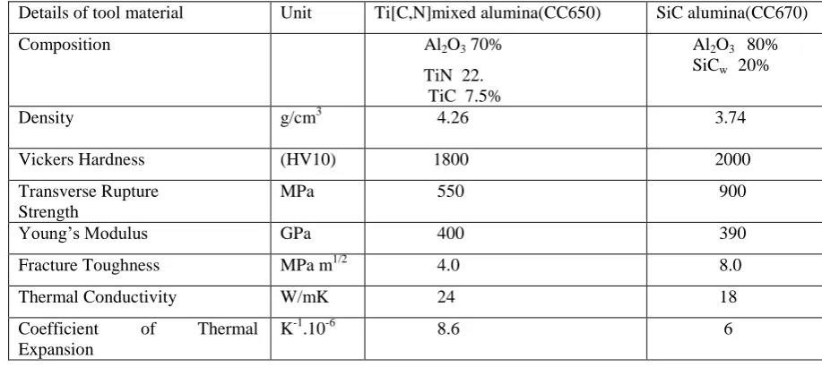
TABLE 3 The properties of the alumina based ceramic cutting tool material
Details of tool material Unit Ti[C,N]mixed alumina(CC650) SiC alumina(CC670)
Composition Al2O3 70%
TiN 22. TiC 7.5%
Al2O3 80% SiCw 20%
Density g/cm3 4.26 3.74
Vickers Hardness (HV10) 1800 2000
Transverse Rupture Strength
MPa 550 900
Young’s Modulus GPa 400 390
Fracture Toughness MPa m1/2 4.0 8.0
Thermal Conductivity W/mK 24 18
Coefficient of Thermal
Expansion
The machining process was performed with
various cutting speed at constant feed rate and
depth of cut. During the machining process flank
wear, surface roughness, and the cutting force was
measured. The flank wear was measured using a
Metzer Toolmakers microscope, the surface
roughness was measured using a TR200 surface
profile meter, and the cutting force was measured
using a strain gauge dynamometer.
3. RESULT AND DISCUSSION
3.1 Flank wear of the alumina cutting tool
Flank wear is the main form of wear in machining
of FRP composite that affects the tool life, surface
quality and production cost. Tool wear occurs due
to the rubbing of the hard fibres to the cutting edge
of the tool which result abrades the cutting tool and
removes some of the tool material at the flank face.
The wear is due to crack development, and the
intersection caused by hard fibre chips acting as
small indenters on the cutting face.
As the cutting speed increases, the velocity of
abrasion and the rate of contact of broken fibre
chips also increase, leading to a higher flank wear
at high speed. Fig.2 shows the variation of flank
wear with respect to machining time while
machining of GFRP composite material using the
Ti[C, N] alumina cutting tool and the SiC whisker
alumina cutting tool at 250 m/min. Fig.3 shows the
flank wear versus cutting velocity of the alumina
cutting tools after 6 min of machining. The flank
wear of alumina cutting tool increases with respect
to speed & machining time. From Fig.2, it can be
noted that Ti[C, N] mixed alumina cutting tool
fails after 8 min of machining at 250 m/min. Tool
failure of the Ti[C, N] mixed alumina cutting tool
after 6 min of machining at 300 m/min. From the
above discussion, it can be noted that chip
formation while machining GFPR material is an
important factor in addition to fibre orientation,
. Fig 2: Flank wear versus machining time of alumina cutting tools while machining GFRP composites.
Fig 3: Flank wear versus cutting velocity of alumina cutting tools while machining GRP composite At 6 min
3.2 Surface Roughness
In machining process, surface integrity is the main
requirement to determine the quality of finished
product. The measurement of surface roughness of
FRP composite is not easy than that of metals
because of strong glass fibre undergoes sharp
brittle fracture with deformation of matrix material,
fibre micro cracking and pulverization. Surface
flaws due to delamination and interlaminar crack
are also observed while machining of GFRP
materials.
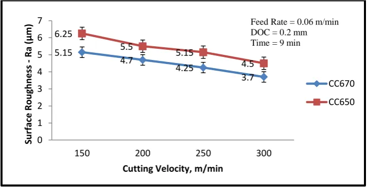
The cutting velocity is the main factor that
affects the surface roughness. Fig.4 shows the
surface roughness versus cutting velocity after
machining GFRP composite with alumina cutting
tool. From Fig.4, it can be concluded that the
surface roughness was to be improved by
increasing cutting velocity and the surface 0.13
0.2
0.28
0.32
0.4
0.15
0.28
0.35
0.4
0.45
0 0.05 0.1 0.15 0.2 0.25 0.3 0.35 0.4 0.45 0.5
2 4 6 8 10
Fl
an
k
Wear
, m
m
Machining Time, min
CC670 CC650 Cutting Velocity = 250 m/min
Feed Rate = 0.06 mm/rev DOC = 0.2 mm
0.06
0.2
0.37
0.1
0.26
0.42
0 0.05 0.1 0.15 0.2 0.25 0.3 0.35 0.4 0.45
100 200 300
Fl
an
k
Wear
, m
m
Cutting Velocity m,min
CC670 CC650 Feed Rate = 0.06
roughness of machined GFRP composite ranges
from 4.5 to 6.5 µm. The advantage of machining
GFRP material by using alumina based ceramic
cutting tool is that they produce better surface
finish other conventional cutting tools. Ceramic
cutting tool eliminate a built-up edge (BUE)
forming during machining.
As the cutting speed increases, the formation
of a BUE is greatly reduced which result surface
roughness decreases. From the above observation,
it can be concluded that SiC whisker reinforced
alumina cutting tool is to produce lower surface
roughness with less surface damage than the Ti[C,
N] mixed alumina cutting tool.
Fig 4: Surface Roughness versus cutting velocity after machining GFRP composite material with alumina cutting tool for 9 min.
3.3 Cutting Force
The cutting force in the machining process is
produced due to the relative sliding motion of
cutting tool against the work piece in order to
remove the material from the work piece. The
cutting tool geometry, tool materials, and
machining parameters are responsible for higher
cutting force. Two main mechanism shows the
cutting force in machining FRP composite are
Shearing & Buckling. In this study, cutting tool
will be perpendicular to the fibre orientation, and
the shearing mechanism persists.
The cutting force was measured by lathe tool
dynamometer while machining of GFRP composite
using alumina cutting tool at a constant feed rate &
depth of cut of 0.06 mm/rev and 0.2 mm
respectively as shown in Fig.5. The maximum
cutting force occurs in the direction of cutting
velocity. The cutting force does not exhibit any
particular trend because of fluctuation of cutting
force in machining of hard abrasive fibres & soft
matrix material. Due to soft matrix material &
amorphous nature of GFRP material, the principle
cutting force is considerably lower than that on
machining of steel.
From Fig.5 it can be concluded that Ti[C, N]
mixed alumina cutting tool produced a higher
cutting force of 265 N at the cutting velocity of 150
m/min than that of the SiC whisker reinforced
alumina cutting tool (220 N for the same cutting
conditions). The cutting force initially decreases as 5.15
4.7
4.25
3.7 6.25
5.5
5.15
4.5
0 1 2 3 4 5 6 7
150 200 250 300
Su
rface
R
o
u
gh
n
e
ss
-
R
a (
µ
m
)
Cutting Velocity, m/min
CC670 CC650
the cutting speed increase but tends to increase at
higher cutting speed above 250 m/min. The initial
decrease in cutting force with respect to cutting
speed is due to decrease in tool chip contact area,
leading to higher reduction in shear strength of the
work piece. As the cutting speed increases, work
hardening occurs in the work piece leads to
increase in tool wear and make it difficult for the
cutting tool to machine the work piece.
Fig.5: Principle cutting force versus cutting velocity of alumina cutting tools while machining GFRP composite at 6 min
4. CONCLUSION
From the above study and analysis, it can be
concluded that the abrasive wear is quite smooth
and less with the SiC whisker reinforced alumina
cutting tool than the Ti[C, N] mixed alumina
cutting tool while machining of GFRP composite
material. The SiC whisker reinforced alumina
cutting tool produce a better surface finish than the
Ti[C, N] mixed alumina cutting tool. Overall
conclusion is the performance of SiC whisker
reinforced alumina cutting tool is better than the
Ti[C, N] mixed alumina cutting tool on machining
of GFRP composite.
REFERENCES
[1] Report of nptel on Engineering Applications of
composite materials, Module 11.
[2] Smith WilliamF, Hashemi Javad. Foundation
of Material Science & Engineering, forth ed,
NY: Mc-Graw Hill International Edition;
2006.
[3] Engineering Materials: Polymer, Ceramics &
Composites by A.K Bhagava
[4] Everstine, G.C., and. Rogers. T.G, 1971, A
theory of machining of fiber reinforced
materials, Journal of Composite. Materials,
Vol. 5, pp. 94-105.
[5] Sakuma.K and M.Seto 1983, Tool-wear in
cutting glass-fiber –reinforced plastics the
relation between fiber orientation and tool
wear, Bulletein of the JSME, Vol. 26 , No.
218: , pp.1420-1427.
[6] Rahman M, Ramakrishnan S, Prakesh S, Tan
DCG, 1999, Machinability study of carbon
fiber reinforced composites, Journal of.
Material Process Technology, Vol. 89-90, pp.
292-297.
220
190 182 187
267
213
200 208
0 50 100 150 200 250 300
150 200 250 300
Pr
in
ci
p
le
C
u
tt
in
g Fo
rc
e
(
N
)
Cutting Velocity, m/min
CC670 CC650
[7] Davim JP, Mata F. 2004, Influence of cutting
parameters on surface roughness using
statistical analysis Industrial Lubrication
Tribology.Vol. 56 No. 5, pp 270-274.
[8] Ramulu. M., Arola, D and Colligan. K., 1994,
Preliminary investigation on the surface
Integrity of fiber reinforced plastics
Engineering systems Design and Analysis,
ASME., Vol. 64 No.2, pp. 93-101.
[9] Takeyama, H. and Lijama, N. 1988,
Machinability of glass fiber reinforced plastics
and application of ultrasonic machining, Annal
of CIRP, Vol. 37, No.1, pp. 93-96.
[10] König.W Ch. Wulf, P. Graß and H.
Willerscheid, 1985 A theory of machining of
fiber reinforced plastics. CIRP Annals
Manufacturing Technology, Vol. 34, pp
537-548.
[11] Palanikumar, K. (2008) . Application of
Taguchi and response surface methodology for
surface roughness in machining glass fiber
reinforced plastics by PCD Tooling,
International Journal of Materials Processing
Technology, Vol. 36, No. (1-2), pp. 19-27.
[12] Palani kunar.K, Karuna moothy. L and
Kathikeyan. R ,2006, Assessment of factors
influencing surface roughness on machining of
Glass fiber reinforced polymer Composites,
Materials & Design Vol. 27, No.10, pp.
863-871.
[13] Adam khan.M and A. Senthil kumar, 2011,
Machinability of glass fiber reinforced plastic
GFRP) composites using alumina based
ceramic cutting tools International Journal of
Manufacturing Process. Vol. 13, No.1, pp
67-73.
[14] Engineering Applications of composite
materials, Module 11 nptel.
[15] Xu CH, Feng YM, Zanga RB, Zhao SK, Xiao
X, Yu GT Wear behaviour of Al2O3 / Ti[C, N] /
SiC new ceramic tool material when
machining tool steel and cast iron. Journal of
Material Processing Technology 2009; 209;
4633.7.
[16] Aslan Ersan, Camuscu Necip, Birgoren Burak.
Design optimization of cutting parameters
when turning hardened AISI 4140 steel
(63HRC) with Al2O3 + Ti[C, N] mixed ceramic
tool. Materials and Design 2007; 28:1618-22. [17] Afghani JED, Yamaguchi K, Horaguchi I,
Nakamoto T. Whisker behaviours and tool
wear in cutting of unidirectional SiC
whisker-reinforced plastic. Wear 1996;195:223-31.
[18] Jianxin Deng, Xuefeng Yang, Jianhua Liu,
Self-lubricating behaviours of ceramic tools in
dry cutting. International Journal of Machining
and Machinability of Materials 2006;