452 | P a g e
Performance Analysis of Square, Circular and Triangular
Fins at Various Pitches
D. Suresh
1, D. Manohar
2, B. Murali Krishna
3,Sk. Khadarvali
4Dr. B. S. Subramanyam
5Mechanical Engineering Department, Viswanadha Institute of Technology and Management,
Visakhapatnam, Andhra Pradesh, (India)
ABSTRACT
Heat transfer between a solid surface and a moving fluid depends on heat transfer coefficient, temperature
difference, and the area of heat transfer. When, the surface temperature, fluid temperature and heat transfer
coefficient are not in our control, we are left with the only alternative of increasing the effective surface area by
using fins or extended surfaces. In the present work, circular, square and triangular fins are separately used
and their performance is studied for various configurations obtained by changing the pitch of the fins. Square
fins gave maximum efficiency and triangular fins gave minimum efficiency, when experiments were conducted
with blower. Irrespective of the type of fins, the efficiency decreased with decrease in number of fins (except
during the presence of 2 fins) and circular fins gave maximum efficiency and triangular fins gave minimum
efficiency, when experiments were conducted without blower. Irrespective of the type of fins the efficiency
decreased with decrease in number of fins (except during the presence of 2 fins). An efficiency of 6% was
obtained when the experiments were conducted with zero number of fins and with blower. An efficiency of
54.1% was obtained when the experiments were conducted with zero number of fins and without blower.
Key words:
Blower, Efficiency, Fins, Pitch, Temperature difference
I.
INTRODUCTION
More heat transfer from the hot surface is possible by increasing the surface area in contact with environment.
For this the surface area exposed to the surroundings is frequently increased by the attachment of protrusion to
the surfaces, and the arrangement provides a means by which heat transfer rate can be substantially improved.
These protrusions are called fins or spines. Heat transfer between a solid surface and a moving fluid is governed
by the Newton’s cooling law: q= hA ), where 'h' is the heat transfer coefficient, 'A' the area of heat
transfer, ' the surface temperature and is the fluid temperature. To increase the convective heat transfer,
it is necessary to increase the temperature difference )' or 'h' or 'A'. Many times, when the first option
), is not in our control and the second option (i.e. increasing h) is already stretched to its limit, we are
left with the only alternative of increasing the effective surface area by using fins or extended surfaces.
Since the 1950’s much progress has been made on the methods used for cooling of different engineering
453 | P a g e
[1] Hani A et al experimentally investigated the enhancement of heat transfer from a discrete heat source inconfined air jet impingement by placing a variety of pin fin heat sinks on the heat source and total fin
effectiveness was computed for the pinned heat sinks relative to the unpinned ones.
[2] Den pong Soodphakdee et al, studied the heat transfer performance of various commonly used fin
geometries such as round, elliptical, or square under inline or staggered arrangement. Studies were
carried out for fixed pitch to provide same wetted area per unit volume as that of the nominal case.
[3] O.N Sara et al carried out studies on the heat transfer and friction characteristics on the convective heat
transfer through rectangular channel with inline arrangement of square section pin fin. They attributed the
heat transfer increase to the additional surface area that is exposed to the fluid when the clearance is
provided.
[4] N.Sahiti et al, has discussed the enhancement of heat transfer rates with circular pin fins of diameter
0.7mm and length 28.2mm with staggered arrangement by using conductive and convective relationships.
II. EXPERIMENTAL ANALYSIS
2.1 Description of Experimental Setup
The experimental test rig consists of fins of circular, triangular or square cross section fitted along a circular
duct. One end of the duct is connected to the heater and other end to the delivery pipe. The second end of the
heater is connected to a fan. Two thermometers are provided to measure the inlet and outlet temperatures of the
air passing through the duct with/without fins, and with/without blower. An anemometer is provided to measure
the velocity of air at the exit. A dimmer stat and ammeter are also provided to measure the heat output from the
heater. Efficiency of the duct was then computed for circular, triangular, and square type of fins of the same area
of heat transfer and for different pitches. A cross sectional area of 2827mm2 was considered for the three types
of fins used. Table.1 illustrates the various configurations of fins and pitches used for our analysis.
2.2 Design and Fabrication of Experimental Setup
Extended surfaces or fins are used to increase the heat transfer rate from a surface to a fluid whenever it is not
possible to increase the value of the surface heat transfer coefficient or the temperature difference between the
surface and the fluid.
It is obvious that a fin surface sticks out from the primary heat transfer surface. The temperature difference with
surrounding fluid will steadily diminish as one moves out along the fin.
The following procedure is adopted during the design and fabrication of the experimental setup:
First and foremost a proper design for square, circular and triangular fins was made as shown in Fig.1, so
that each had the same cross-sectional area of 2827mm2.
Aluminum was considered as the fin material because of its good thermal conductivity.
Two Aluminum plates each of 6mm thickness and 100mm width and having a length of 12 feet were taken
454 | P a g e
Square fins of side 53mm and triangular fins of side 80mm were made with hand cutting tools, whereascircular fins of diameter 60mm were worked out on a lathe machine .
In order to get an accurate size of 32mm hole, boring operation was done.
Thus a total of 36 number of fins of each type were prepared.
Fins were then put over an aluminum duct as shown in Fig.2.
Galvanized iron ducts, elbow joint, and collars were also used to complete the required experimental setup.
The entire unit was then firmly fixed on a steel frame with wooden platform.
A blower with a funnel shaped channel made up of sheet metal was used blow the air through the duct.
A nichrome coil was wound around a galvanized duct for heating purpose and was then insulated on the
outer surface with asbestos rope.
An Ammeter, voltmeter, switches, and an anemometer were used to measure the required parameters.
Finally a dimmerstat was connected to the circuit to give the required heat input.
Two holes were made at each end of the aluminum pipe (on which fins were arranged) in order to place the
thermometers for measuring the inlet and outlet temperatures of air.
To ensure safety, all the connections were thoroughly checked before starting the experimentation. Fig.3
shows the complete assembly of Experimental setup.
2.3 Experimental Procedure
The main objective of this experimental set up is to study and analyze the effect of various types of fins at
different pitches on the efficiency. The following procedure is adopted to study the objective.
Phase 1:
The following steps are adopted
Place 36 number of square fins on aluminium duct ensuring a uniform pitch of 1.1 cm and fit it in its
position as shown in Fig. 2.
Give single phase power supply to the unit .
Using dimmerstat give on input of 80V.
Switch on the blower.
After attaining steady state measure the temperature of air at the inlet and outlet of the duct. Also measures
the velocity of air at the exit of the pipe using an anemometer.
Switch off the power supply to the unit.
Repeat all the above steps for other configurations as given in Table: 1. Calculate the efficiency as shown section III..
Phase 2:
Repeat phase 1 with circular type of fins .
Phase 3:
Repeat phase 1 with triangular type of fins.
Phase 4:
Repeat phase 1, phase 2, phase 3 without using blower.
455 | P a g e
Actual heat flow rate Qa =mCpwhere m (mass of air in kg/s)
A= (circular area of duct in m2)
= Density of air (kg/m3)
D = Diameter of pipe (m)
C = velocity of air (m/s)
Ti = Temperature of air at inlet (
To= Temperature of air at the outlet (
= Ambient temperature (
Properties of air were taken at mean film temperature ‘( )’ = 2
Efficiency of fin, 'η' = (Actual heat transfer by fin)/(max possible heat transfer by fins)
= mCP / mCP
IV.FIGURES AND TABLE
456 | P a g e
Fig.2 Fabrication of fins
Fig.3 Experimental set up
Fig.4 Comparison of variation in efficiency of Square, Circular, and Triangular types with number of fins (with
457 | P a g e
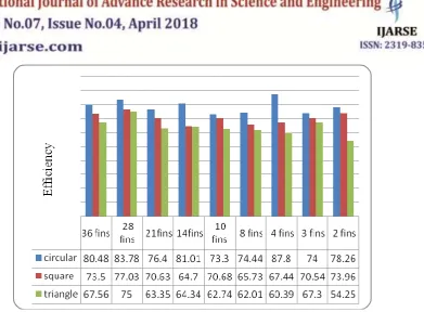
Fig 5 Comparison of variation in efficiency of Square, Circular, and Triangular types with number of fins(without blower)
Table: 1 Various configurations of fins and pitches used in the analysis
S.No. Types of fins No of fins Pitch
(cm) 1
Circular, Square
Triangular
36 1.1
2 28 1.5
3 21 2.0
4 14 2.9
5 10 4.0
6 8 4.9
7 4 8.8
8 3 11.0
9 2 14.7
10 1 22.0
V. CONCLUSIONS
The following conclusions are drawn after conducting a series of experiments.
It is observed from Fig.4 'Comparison of variation in efficiency of Square, Circular, and Triangular types with
number of fins with blower', that square fins gave maximum efficiency and triangular fins gave minimum
efficiency, when experiments were conducted with blower.
The maximum and minimum efficiencies obtained for square fins were 25.47% and 17.18% respectively.
The maximum and minimum efficiencies obtained for circular fins were 24.75% and 15.57% respectively.
The maximum and minimum efficiencies obtained for triangular fins were 20.9% and 13.29% respectively.
Irrespective of the type of fins the efficiency decreased with decrease in number of fins due to the reduction
458 | P a g e
The sudden increase in efficiency in the presence of 2 fins can be attributed to the fact that the air between finsno more remains stagnated and is more free to move.
Though the area of square, circular and triangular fins is same, it is geometrically found that the corners of
square, circular and triangular were at a distance of 35, 30 and 48 mm respectively, from the centre of the duct.
The triangular fins gave minimum efficiency as its corner was 48mm from the centre of the duct and was more
when compare to that of square and triangular fins. However both circular, square fins gave almost the same
efficiency as the distance of their corners from the centre were almost the same.
It is observed from Fig.5 'Comparison of variation in efficiency of Square, Circular, and Triangular types with
number of fins without blower', that square fins gave maximum efficiency and triangular fins gave minimum
efficiency, when experiments were conducted without blower .
The maximum and minimum efficiencies obtained for circular fins were 87.8% and 71.05% respectively.
The maximum and minimum efficiencies obtained for square fins were 77.03% and 64.7% respectively.
The maximum and minimum efficiencies obtained for triangular fins were 75% and 54.25% respectively.
Irrespective of the type of fins the efficiency decreased with decrease in number of fins due to the reduction
in heat transfer area (except during the presence of 2 fins).
The sudden increase in efficiency in the presence of 2 fins can be attributed to the fact that the air between
fins no more remains stagnated and is more free to move.
However when the experiment is conducted without blower, the efficiency of circular fins was more than that of
square fins as the area was more uniformly distributed in the case of circular fins and that the contribution of
surface area for heat transfer is more when there is no blower.
An efficiency of 6% was obtained when the experiments were conducted with zero number of fins and with
blower. An efficiency of 54.1% was obtained when the experiments were conducted with zero number of fins
and without blower. The increase in efficiency can be attributed to the fact that the entire heat transfer is due to
fins only and there is no contribution of the blower.
REFERENCES
[1] Hani A. El-Sheikh and Suresh V.Garimella, June 2000, Enhancement of air jet impingement Heat Transfer
Using Pin-Fin Heat Sinks, IEEE Transactions on Components and Packaging Technology, VOL. 23, No.2.
[2] DenpongSoodphakdee, MasudBehnia, and David Watabe Copeland, 2001, A Comparison of Fin Geometries
for Heat sinks in Laminar Forced Convection: Part I – Round, Elliptical, and Plate Fins in Staggered and In-line
Configurations. The International Journal of Microcircuits and Electronic Packaging, Volume 24, Number 1,
First Quarter, (ISSN 1063-1674).
[3] O. N. Sara, S. Yapici, M Yilmaz, 2001, Second law analysis of rectangular channel with square pin-fins, Int.
comm…Heat and mass transfer Vol 28. No. 5.pp 617-630.
[4] N. Sahiti et al, F. Durst, A. Dewan, 2005, Heat transfer enhancement by pin elements, International Journal