VOICE COMMAND BASED CALAMITY RECUE
ROBOT
Reema Mathew A
1, Aswani Johnson
2, Linta Thomas
3, Rosemary Jacob
4 1,2,3,4Dept. of Electronics and Instrumentation Engineering,
Vimal Jyothi Engineering College, Chemperi, Kannur, (India)
ABSTRACT
A rescue robot is a robot that has been designed for the purpose of aiding in most rescue workforces. In most of common circumstances that skill rescue robots are mining fortunes, urban ruins, and imprisoned situations and blasts. This robot will help us in these situations by helping humans. The major objective of this project is to control the robot by using voice commands and to use in disaster regions. It is aimed for the users to control a pick and place device through voice commands. Here the user can control all the movements of robot through voice commands to remove the objects in disaster regions. It uses a microphone to convert the given voice commands to electrical signals and this signal is recognized using voice recognizer by means of a voice sensor. This sensor is known as the VR Module. It will produce an output which is used by a controller to produce a control output. This output will drive the motor, thus robotic action takes place. It consists of L293D IC which will as a driving mechanism of the pick and place robot. Also, it has servomotor that helps for movement of arms. The two micro servos are used in gripping the objects at a distance. The VR module is used here to recognize the voice and give the output to microcontroller. If the signal is same with that of the trained signal in keypad, the servos will work according to it.
Keywords: ATmega 328, VR Module (easyVR3.0), L293D
I. INTRODUCTION
Nowadays robots are having wide applications in various fields. In many industries robots are used for
performing different functions. Robots are more accurate and efficient as compare to human being. Use of
robots in industries can increase the quality of products and their production rates. As compare to earlier days,
today robots are used in various areas such as defence & medical fields, in industries etc.
Many areas of the world are getting affected due to natural calamity. Disasters are exceptional & unstoppable
events that are either manmade or natural. Voice controlled robot is an interesting project, mainly used for
industrial and surveillance applications. This is a system which will act automatically when the voice command
is reached. These voice commands should ensure the various operations that is to be performed. Our project is
aimed to see the working
of
a pick and place device using voice commands at calamity affecting regions.The system uses one voice recognition (VR) Module namely EasyVR3.0 for the application and recognition of
voice commands. This module will produce a signal and this signal is given to the microcontroller.
Based upon the signal from the microcontroller the motor connected in the robotic system runs and thus robotic
action will take place.
The advantages of voice controlled robots are hands-free and fast data input operations. In future voice
recognition system will have greater usages in calamity, defence and industrial regions. Normally the
handicapped people cannot operate manual controlled robots. These people can use only their voice. And there
are a lot of regions where the human cannot involve. So we decided to design the voice controlled robot since
researches are going on.
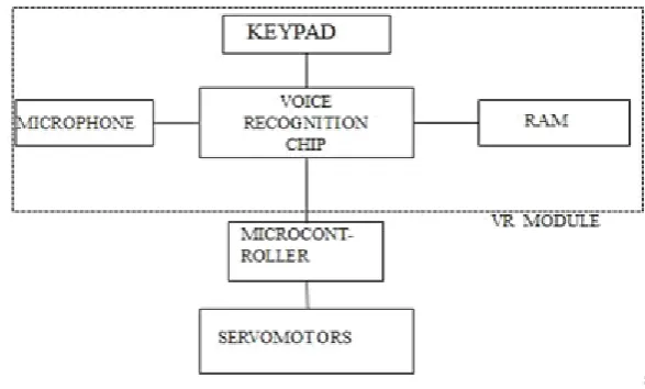
II. BLOCK DIAGRAM
Fig 1: Block Diagram
2.1 Voice Recognition Module
This voice recognition module is used to recognize the voice or sounds. It receives configuration commands or
responses through serial port interface. With this module, we can control many devices through our voice. This
module can store up to 15 pieces of voice instructions. Those 15 pieces are divided into 3 groups, with 5 in each
group. First we should train the module with voice instructions group by group. After that, we should import one
group before it could recognize the 5 voice instructions within that group. If we need to implement instructions
in other groups, we should import the group. This module is speaker dependant
Here the Easy VR module is used, with specification 3.0. It is a voice recognition shield for Arduino boards
integrating an Easy VR module. It includes all of the features of the Easy VR module in a shield form factor
that simplifies connection to the Arduino main board and PC.
Easy VR 3.0 is a multi-purpose speech recognition module designed to add versatile, robust and cost effective
speech and voice recognition capabilities to virtually any application. Easy VR is the third generation version of
2.2 Atmega 328
At mega 328 is a single chip microcontroller designed by ATMEL and belongs to system where a simple, low
powered, low cost microcontroller is needed. Operating voltage 5v.Input voltage 7-12v.Digital I/O pins is 14(of
which 6 provide PWM output).ATMEL AVR 8-bit and 32 –bit microcontrollers deliver a unique combination of
performance ,power efficiency and design flexibility for a wide range of applications.
Fig 2.Pin diagram of ATMEGA328
2.3 Motor Driving System
Motor driving system of calamity rescue robot consists of mainly servomotors and micro servomotors Both the
servo motor and micro servomotors are used for making the angular movements. Both the motors can provide
an angle of rotation.
Servomotors are working on the basis of coming input pulses. Servo motor can control the machinery of the
system. It is a kind of very small auxiliary motor indirect variable speed device, servo motor speed is controlled
by the input signal, and can in the fastest time to respond. It provides an angle of rotation based upon the
coming pulses.
Micro servomotors are similar to servomotor motor, but these are small as compared to the servomotor. It can
also provide an angle of rotation. Therefore, it can be used to provide the gripping action of the pick and place
robot. Micro servomotors are light weight high output power. Servo can rotate approximately 180 degrees (90
in each direction), and works just like the standard kinds but smaller. We can use any servo code, hardware or
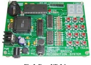
III. HARDWARE
3.1 Voice Reconition Module
Voice recognition module is a multi-purpose speech recognition module designed to easily add versatile, an
UART interface powered at 3.3v – 5v, such as PIC and Arduino boards. Some applications examples include
home automation, such as voice controlled light switches, locks, curtains or kitchen appliances, or adding
“hearing” to the most popular robots on the market.
The outer headers J1 and J2 are the mikroBUS™ interface connectors, providing selectable 3.3V/5V power
input to the module and voltage translated digital I/O lines, including: UART receive/transmit lines and control
pins.
Fig 3. Easy VR 3.0
3.1.1 Microphone
The microphone provided with the Easy VR 3 module is an Omni directional electrets condenser microphone
(Horn EM9745P-382): Sensitivity -38dB (0dB=1V/Pa @1KHz) .Load Impedance is 2.2K. Operating Voltage is
3V. Almost flat frequency response in the range 100Hz – 20 kHz. The microphone circuit is optimized for use
at ARMS_LENGTH (default, about 60cm) or FAR_MIC distance settings.
If we use a microphone with different specifications the recognition accuracy may be adversely affected.
Differences in rated load impedance and sensitivity can be compensated to a certain extent by changing the
microphone gain. This can be done in several ways: Replacing the internal gain resistor R4 (1.2kΩ). Adding an
external resistor Rx going in parallel with R4 (it can only reduce gain, useful for HEADSET distance settings).
Removing the internal resistor R4 and using only the external resistor Rx.
3.1.2 Voice Recognition Chip
Voice recognition chip is the heart of the entire system. HM2007 is a voice recognition chip with
on-chip analog front end, voice analysis, recognition process and system control functions. The input voice
command is analysed, processed, recognized and then obtained at one of its output port which is then decoded,
amplified and given to motors of robot. The peculiarity of HM 2007 is that it has much more accuracy and
reliability.
The chip provides the options of recognizing either forty 0.96 second words or twenty 1.92 second words. This
The chip has two operational modes; manual mode and CPU mode. The CPU mode is designed to allow the
chip to work under a host computer. This is an attractive approach to speech recognition for computers. Because
the speech recognition chip operates as a co-processors to the main CPU. The jobs of listening and recognition
don’t occupying any of the computers CPU time. When the HM 2007 recognizes a command it can signal an interrupt to the host CPU and then relay the command code. The HM 2007 chip can be cascaded to provide a
larger word recognition library.
3.1.3 Keypad
The keypad is used for training the chip used in the system. By, training the chip to certain commands the robot
can take successive motions. Also, there is definite memory location for voice commands
.
3.1.4 RAM
The RAM in VR module provides the storage facility. It can store the command signals which are applied to the
system. It stores decoded voice commands by the chip at the assigned locations. Thus, RAM can store all the commands given to the VR module .This helps to check the commands when there is problem associated with
the system. The RAM of VR module has the same function as the RAM in central processing unit in the
computer.
3.2 Servo Motor
Servo motor can control the machinery. It is a kind of very small auxiliary motor indirect variable speed
device, servo motor speed is controlled by the input signal, and can in the fastest time to respond in the
automatic control system plays a very important role, servo motor has a mobile time, high linearity, click start a
low voltage dynamic characteristics of servo positioning location is accurate, able to convert voltage signal into
torque and rotational speed for the drive control object.
The main function of the servo motor, with the speed change control voltage uniform and stable, the servo
motor to position mainly by the pulse, a pulse current when received, will be a corresponding angle of rotation
corresponds to one pulse in order to achieve unique, because the servo motor itself has a pulse current issue
features an angle of rotation will be issued whenever the corresponding number of pulse, pulse and servo motor
to accept the formation of echoes, or called closed-loop, thisway, the system will know how many pulses sent to
the servo motor, while the number of pulses received back, so it can accurately control motor rotation, precise
positioning can be achieved 0.001mm.
3.3 Micro Servomotor
Micro servomotor is a tiny and lightweight motor with high output power. Servo can rotate approximately 180
degrees (90 in each direction), and works just like the standard kinds but smaller. We can use any servo code,
hardware or library to control these servos. Good for beginners who want to make stuff move without building a
motor controller with feedback & gear box, especially since it will fit in small places. It comes with a 3 horns
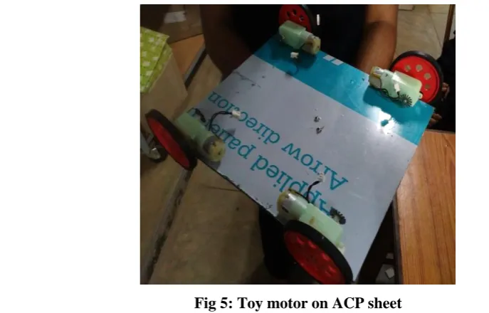
3.4 Toy Motor
Toy motor is another type of motor that can be used for the movement of picks and place robot. It is typically an
electric motor that uses the principle of electromagnetism. Electromagnetism is the force that transforms electric
power from the battery into mechanical power in the toy car’s wheel. It consist of steel that forms the body of
the motor, an axle(shaft), a nylon end cap and two battery leads. The nylon end cap is held in place by two tabs
that are part of the steel can . By bending the tabs back, we can free the end cap and remove it. Inside the end
cap are the motor’s brushes. These brushes transfer power from the battery to the commutator as the motor
spins.
3.5 Motor Driving Mechanism – L293d
L293D is a typical Motor driver or Motor Driver IC which allows DC motor to drive on either direction. L293D
is a 16-pin IC which can control a set of two DC motors simultaneously in any direction. It means that we can
control two DC motor with a single L293D IC. Dual H-bridge motor driver integrated circuit(IC).
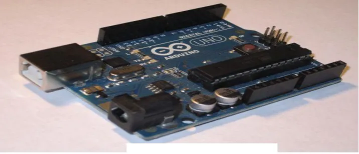
3.6 Micro Controller-Arduino
Arduino is an open – source platform used for building electronics projects. Arduino consists of both physical
programmable circuit boards (often referred to as a microcontroller) and a piece of software, or IDE (Integrated
Development Environment) that runs on our computer, used to write and upload computer code to the physical
board.
The Arduino platform has become quite popular with people just starting out with electronics, and for good
reason. Unlike most previous programmable circuit board, the Arduino doesn’t need a separate piece of
hardware (called a programmer) in order to load new code on to the board- we can simply use a USB cable.
Additionally, the Arduino IDE uses a simplified version of C++, making it easier to learn to program. Finally,
Arduino provides a standard form factor that breaks out the function of the micro-controller into a more
accessible.
connection, a power jack, an ICSB header, and a reset button. It contains everything needed to support the
microcontroller simply connect it to a computer with a USB cable or power it with a AC to DC adapter or
battery to get started. The UNO differs from on proceeding boards in that it doesn’t use the FTDI USB-to-serial
driver chip. In still, it features the AT mega 8U to programmed as a USB-to-serial converter.
The high-performance AT mega 8 bit AVR RISC-based microcontroller combines 32KB ISP flash memory
with read-while-write capabilities, 1 KB EEPROM, 2 KB SRAM, 23 general purpose I/O lines, 32 general
purpose working registers, three flexible timer/counters with compare modes, internal and external interrupts,
serial programmable USART, a byte-oriented 2-wire serial interface, SPI serial port, 6-channel 10-bit A/D
convertor (8 channels in TQFP and QFN/MLF packages ), programmable watchdog timer with internal
oscillator, and five software selectable power saving modes. The device operates between 1.8 – 5. 5volts.
By executing powerful l instructions in a single clock cycle, the devices achieve throughputs approaching 1
MIPS per MHz, balancing power consumption and processing speed.
3.7 Acp Sheet
ACP sheet means Aluminum Composite Panel. These sheets are made from non combustible polyethylene core
that is further laminated and sandwiched between the two finest aluminium sheets. For complete corrosion
resistance and weather protection, external surface of the aluminium is coated with PVDF resin. Besides this,
the inside of the aluminium surface is also coated with polyester for a smooth surface. These aluminium
composite panel sheets are widely used for designing false ceilings, advertisement boards and partitions. Here
ACP sheet provide the base of the robotic system.
3.7.1 Design Steps
The design steps involving are the interfacing of the VR module to the Arduino and the mechanical construction
of pick and place robot. After this construction, the voice signal through the microphone is given to the VR
chip.VR chip recognize the command and the signal output is given to the microcontroller. The corresponding
signal from the controller will control robotic action.
3.7.2 Fixing of Toy Motor
Toy motors are fixed at the ACP sheet and it provides the front and backward motions for the robot. Thus by
using the toy motor driving system, the motion of the robot is permissible. Toy motors are the simple motors
which are acting on the principle of electromagnetism.
3.7.3 Arm Construction
Arm construction of pick and place robot is done by using servomotor. Here the servomotor can provide the arm
movements. Generally, the servomotor provides the angular motion of the robotic arm. Servomotor rotation will
be provided by the microcontroller used.
Fig.6: Arm 1 Fig 7: Arm with base
3.7.4 Final Pick And Place Robot
Fig 8: Final Robot Fig 9: VR Module Used
IV. CONCLUSION
With the completion of our project, we learned the basics of some new technologies including Arduino
programming and easy VR sensor. This project also helped us in learning how to manage a project.We have
designed the voice command based pick and place robot which can act as calamity rescue robot. This robot can
work with the given voice commands. But, only standard commands can be used here to perform the robotic
operation. Standard commands means the trained commands. For performing the robotic operation we will train
the robot to perform different operations. Since, difficult portion of the construction was voice recognition of
input commands, voice controlled robotic arm for picking and placing an object was successfully designed. The
robot control was found to be user friendly.
REFERENCES
[1]. http://www.talkingelectronics.com/John/SpeechRecognition.html
[2]. http://www.imagesco.com/articles/hm2007/
[3]. www.atmel.com
[4]. www.veear.eu
[5]. www.robots.com
[6]. en.wikipedia.org/wiki/rescue-robot
[7]. https://www.arduino.cc/
[8]. https://www.sparkfun.com/products/13316
[9]. www.electronicaestudio.com/docs/SHT-151m.pdf
[10].www.instructables.com/id/Arduino-voice-control/
[11].https://www.robots.com/applications/pick-and-place
[12].Pratik Chopra, Harshad Dange, “Voice Controlled Robot” , Dept. of Electronics Engineering( K.J