DESIGN & ANALYSIS OF PLASTIC INJECTION
MOULD USING NX-UG & DELCAM SOFTWARE
Prof. Patil Satish N
1, Prof. Shinde V.B
2,
Prof. Borkar B.R
3 1M.E. Student,
2,3Asst. Professor, AVCOE, Sangamner
ABSTRACT
The injection moulding machine is a machine that melt plasticize the moulding material inside the heating
cylinder and inject this into the mould tool to create the moulded product by solidifying inside it. There are
several types in the injection machine. Ex. horizontal injection machine, vertical injection machine etc. In past
Mould Design process was time taking as well as hectic. At first Drawing board and then 2D software were
used after which patterns were made. But in this case the results were not convincing most of the times. Thus the
design to market time increased immensely and also project cost required was on a higher side. Due to the
technological advancement the process of Mould Design has fastened and also the results are convincing. With
the help of 3D software we can create Parametric Design, which is editable. Also we can look at number of
possibilities for designing a mould. Most importantly the process of Drawing Creation for Mould Design
becomes very easy. In a 3D software Visualization of our creation is easy possible. Thus the design to market
time shrinks immensely also the project cost required is on lower side. The paper aims at the awareness of
advances of the new age technology of 3D CAD/Mould Wizard for Mould Design.
Keywords:
3D CAD/ Mould design software, Injection Moulding, Mould Design.
I. INTRODUCTION
Injection moulding is an extensive global manufacturing process for making simple to intricate plastic, ceramic and metal parts which vary greatly in their size, complexity, and application. Injection moulding converts wax, thermoplastics, thermo sets as well as powdered metals and magnesium into thousands of products.
Today‟s competitive environment demands that in order to survive in the market, entrepreneurs need to ensure
that their products get designed and manufactured in the minimum possible time, and in the lowest cost, without compromising on the quality aspect. The advent of CAD / CAM has paved the way for a highly flexible, accurate, fast and integrated approach for creating and manufacturing products.
Advanced CAD and CAM software package allow us the transition smoothly from Product Design, Mould design, to CNC Programming and CNC machining. A CAD Software includes a variety of Creation tools which allow us to create a 3D representation of the product. These allow creation of 2D lines, arcs, fillets and wire frames, and then allow us to use these 2D features to build 3D Surfaces or Solids. The basic surfaces created, can further be modified using Modification tools, so as to obtain the final product.
cannot be obtained by manual machining on conventional machines. We need to use High precision CAM software which gives us simulation of machining and codes are automatically generated. After the G and M codes are generated we send them to VMC Machine for Manufacturing.
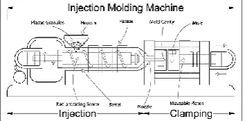
II. INJECTION MOULDING OVERVIEW
Injection moulding is a manufacturing process for producing parts from both thermoplastic and thermosetting plastic materials. Material is fed into a heated barrel, mixed, and forced into a mould cavity where it cools and hardens to the configuration of the mould cavity. After a product is designed, usually by an industrial designer or an engineer, moulds are made by a mould maker (or toolmaker) from metal, usually either steel or aluminium, and precision-machined to form the features of the desired part. Injection moulding is widely used for manufacturing a variety of parts, from the smallest component to entire body panels of cars.
Fig. 1 Injection moulding overview
2.1 Fundamentals of Polymers
Polymers are a large macromolecule built up of repetition of small and simple chemical units called monomers. Polymer can be of long chain molecules or branched long chain molecules or molecules of interconnected three dimensional networks. The repeat unit of the polymer is equivalent or nearly equivalent to the monomer or starting material from which the polymer is formed.
Fig. 2 Schematic Diagram of Plastic Injection Moulding
2.2 Thermoplastic Materials
The term plastics refer to a vast range of materials based on macro molecular organic components. Traditionally plastics have been divided into two major clarification attempts to categories plastic on the basis of the chemical structure of the polymer constituent. Sometimes based on the tonnages of plastics used, references also made to „commodity‟ or large-huge plastics and specialty polymers bit this basis is purely commercial and naturally is
2.3 Mould Fabrication
The machine must be accurate in giving correct injection pressure, moulded temperature control system, proper alignment between the two plates etc. A good injection moulding machine will definitely give consistent good quality products. The different types of plastics materials used for producing various products must be of good graded quality.
2.4 Process Characteristics
1. Utilizes a ram or screw-type plunger to force molten plastic material into a mould cavity. 2. Produces a solid or open-ended shape which has conformed to the contour of the mould. 3. Uses thermoplastic or thermoset materials.
4. Produces a parting line, spur and gate marks.
2.5 Advantages of Injection Moulding
1. Accuracy in weight of articles
2. Choice of desired surface finish and colors 3. Choice of ultimate strength of articles 4. Faster production and lower rejection rates 5. Faster start-up and shut down procedures 6. Minimum wastage
7. Stability of processing parameters
8. Versatility in processing different raw materials 9. Option in article sizes by changing the mould
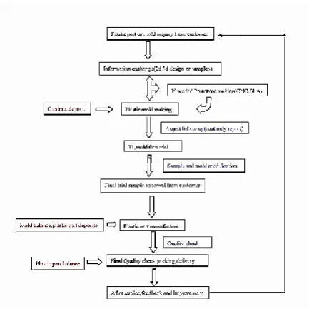
III. METHODOLOGY
IV.
PRODUCT DEVELOPMENT CYCLE
Modelling (CAD): In 3D CAD i.e. Unigraphics NX (Siemens product) software we can design the product
concept we can create drawing views automatically using the 3D model, we can create assembly and we can check for interferences and also we can check motion simulation.
Mould Wizard (MWZ): Using mould Wizard module of Unigraphics NX (Siemens product) the process
of mould Design can be done with ease as well as in least time. This wizard helps us in Creating Core & Cavity. Standard library helps us in selecting mould Base, Ejector pins, Sprue Bush, Locating Ring, Sliders, Runner gating, Cooling Lines etc. Also the Drawing Views of all the parts are created automatically which we can draft as per our requirement.
Mould Flow Analysis: computer-aided engineering (CAE) simulation programs for plastics moulding
processes. It is used widely by the plastics injection moulding industry. The MOULDFLOW injection moulding Simulation of polymers can provide information on the thermo-mechanical properties and residual stresses of the Part resulting from the manufacturing process.
Mould drawing: In mould Wizard, there are options by selecting which we can create standard drawing
views, Hole Table (Ordinate Dimensions) as well as part list as per our requirement. Also dimensioning the parts is easy. We can create section views as per our requirement.
Mould Manufacturing (CAM): In CAM we can generate the CNC Codes, Specify the Tool Path, Specify
Tools, Check for Collision, Check Simulation on the Part that we have designed using CAD. We can avoid the accidents that may be caused while manual programming on CNC or VMC Machines.
V. MANUFACTURING OF PRODUCT
5.1 Injection Moulding Process Cycle
The process cycle for injection moulding is very short, typically between 2 seconds and 2 minutes, and consists of the following four stages:
a) Clamping
Prior to the injection of the material into the mould, the two halves of the mould must first be securely closed by the clamping unit. Each half of the mould is attached to the injection moulding machine and one half is allowed to slide. The hydraulically powered clamping unit pushes the mould halves together and exerts sufficient force to keep the mould securely closed while the material is injected. The time required to close and clamp the mould is dependent upon the machine - larger machines (those with greater clamping forces) will require more time. This time can be estimated from the dry cycle time of the machine.
b) Injection
The raw plastic material, usually in the form of pellets, is fed into the injection moulding machine, and advanced towards the mould by the injection unit. During this process, the material is melted by heat and pressure. The molten plastic is then injected into the mould very quickly and the build-up of pressure packs and holds the material. The amount of material that is injected is referred to as the shot. The injection time is difficult to calculate accurately due to the complex and changing flow of the molten plastic into the mould. However, the injection time can be estimated by the shot volume, injection pressure, and injection power.
c) Cooling
The molten plastic that is inside the mould begins to cool as soon as it makes contact with the interior mould surfaces. As the plastic cools, it will solidify into the shape of the desired part. However, during cooling some shrinkage of the part may occur. The packing of material in the injection stage allows additional material to flow into the mould and reduce the amount of visible shrinkage. The mould cannot be opened until the required cooling time has elapsed. The cooling time can be estimated from several thermodynamic properties of the plastic and the maximum wall thickness of the part.
d) Ejection:
VI. INSPECTION REPORT
Fig.5 Inspection Report
VII. CONCLUSION
The design of the product using Unigraphics (NX 6) software is done and the analysis using NX-Mouldflow software and design of the mould using NX-Mould Wizard. The manufacture of the mould using Delcam-PowerMILL software.
From this new design of mould following results are obtained-Increase in quality of product, Reduction in design time, Production cost per unit decreased, Increase in profit, Material saving, Reduction in design cost. The results reveal that the new age technology of 3D CAD/Mould Wizard along with the CAE makes Complex Mould Designs, Drawing Creation, Material Flow Simulation easier and fast.
REFERENCE
[1]. Kuang-Hua Chang and Chienchih Chenhave studied “3D Shape Engineering and Design Parameterization”(2011).
[2]. J.Q. Ran, M.W. Fu, "Design of internal pins in injection mould CAD", „Elsevier Ltd.‟,2010, Paper no. 0010-4485, Page No. 582-597.
[3]. Mohd. RizwanHamsin, Azuddin Mamat & Aznijar Ahmad-Yazid, “Design and analysis of multi-cavity traditional and-branching runners for plastic injection mould”, „The institution of engineers', June 2009, Vol. no.71, paper No.2, Page No.22-35.
[4]. Zone-Ching Lin and Ming-Ho Chou “Design of the Cooling Channels in Nonrectangular Plastic Flat Injection Mould”, Journal Of Manufacturing System, Department of Mechanical Engineering, National Taiwan University of Science and Technology, Taiwan, R.O.C,2002,Vol. no.21/no.3,Page no.167-186. [5]. C.K. Mok, K.S. Chin, Hongbo Lan "An Internet-based intelligent design system for injection moulds"
[6]. Jiaren Jiang , Xing Yang Liu, "Dimensional variations of castings and moulds in the ceramic mould casting process",Journal of Materials Processing Technology 189,2007,Page no.247–255.