1949 |
P a g e
Optical SNR Improvement Using Multi Stage EDFA With
Dispersion Compensation Using FBG Placement
Optimization Techniques
Abha Jain
1, Anurag Paliwal
2, Khushal Agrawal
31.
M.Tech Scholar, (Digital Communication) Geetanjali Institute of technical Studies Udaipur,
Rajasthan (India)
2.
Assistant Professor (Digital Communication) Geetanjali Institute of Technical Studies Udaipur,
Rajasthan (India)
3.
Sr. Engineer (Inst), Udaipur Cement Works Ltd. Dabok –Udaipur ,Rajasthan()
ABSTRACT
Fiber optic systems are of the backbone to modern day communication networks. The high bandwidth and data rates provided by fiber optics con truly be utilized by employment of WDM (wavelength division multiplexing) techniques. The WDM system is able to cater to a pleoethera of integrated broadband services combining voice, data, video, multimedia services and VAS (Value Added Services). WDM system long widely used in large distance lines suffers from problems such as a dispersion and attenuation which results degraded system performance. Dispersion compensation and optical power amplification are essential parameters in WDM systems. This work is about exploitation of multistage EDFA( Erbium Doped Files Amplifier) system to enhance power and reduce dispersion and achieve higher SNR(Signal Noise Ratio) as composed to signal EDPA of some source power. It is also imperative that by placement of stager of EDPA pre and post FBG, allow for an order of magnitude increase in SNR and achieve excellent DC (Dispersion Compensation) in WDM systems.
Keyword: Optical fiber, WDM system, FBG, DC, multistage EDPA, pre and post FBG EDPA.
I. INTRODUCTION
Optical fiber
The latest advancement which transmits data and prepared for transmitting messages module onto light waves.
With uses glass (or plastic) strings (fibers)to transmit. A fiber optic connection contains a store of glass strings,
each of which is prepared for transmitting messages adjust onto light waves.[1]
Wavelength Division Multiplexing
In fiber optic correspondence structure, wavelength-division multiplexing (WDM) is a progression which
multiplexes distinctive optical transporter signals onto a solitary optical fiber by utilizing arranged wavelength
(i.e. tones) of laser light. This technique empowers bidirectional exchanges more than one strand of fiber, and
what's more duplication of most extreme. A WDM structure utilizes a multiplexer at the transmitter to join the
1950 |
P a g e
to have a gadget that do both in the meantime and can fill in as an optical fuse drop multiplexer. This is reliably
done by utilization of optical-to-electrical-to-optical (O/E/O) interpretation at the very edge of the vehicle deal
with, accordingly allowing spread operation with existing gear with optical interfaces.
Dispersion Compensation Fiber (DCF)
Electronic adjust systems are used as a piece of procedure. Since there is quick acknowledgment at the collector,
coordinate bendings in the optical space, e.g. chromatic dissipating, are changed over into non straight
mutilation after optical - to-electrical change. It is a direct result of reason that the possibility of nonlinear
channel exhibiting realized. For this for the most part support forward equalizer (FFF) and decision feedback
equalizers (DFE) structures are used. EDC shows up down the speed of correspondence since it backs off the
modernized to simple discussion.
Fiber Bragg Grating (FBG)
Optical fiber Bragg grinding (FBG) has starting late found a commonsense application in compensation of
diffusing expanding in whole deal correspondence. In this, Chirped fiber grinding (CFG) is favored. CFG is a
little all-fiber inert device with low expansion disaster that is immaculate with the transmission system and
CFG's dissipating can be easily adjusted. CFG should be arranged in-line for optical results. This is the favored
strategy because of its purposes of enthusiasm including little impression. Low expansion disaster dissipating
incline compensation and irrelevant non-straight effects. In any case, the plan using FBG is mind boggling
Misinterpretation. [2, 3]
What is EDFA?
Erbium-doped fiber enhancer (EDFA) is an optical repeater gadget that is used to support the power of optical
signs being helped through a fiber optic interchanges framework. An optical fiber is doped with the uncommon
earth component erbium so that the glass fiber can assimilate light at one recurrence and radiate light at another
recurrence.
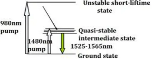
Working Principles of EDFA
The erbium-doped fiber (EDF) is at the focal point of EDFA development, which is a customary silica fiber
doped with Erbium. Right when the Erbium is lit up with light essentialness at a proper wavelength (either 980
nm or 1480 nm), it is impelled to a long-lifetime midway state, by then it spoils back to the ground state by
exuding light inside the 1525-1565 nm band. The Erbium can be either pumped by 980 nm light, in which case
it experiences a flimsy short lifetime state before rapidly decaying to a semi stable state, or by 1480 nm light in
which case it is particularly anxious to the semi stable state. Once in the semi stable state, it decays to the
ground state by delivering light in the 1525-1565 nm band. This spoil strategy can be vivified by earlier light, in
1951 |
P a g e
Figure 1: The working standards of EDFA
Basic design of EDFA
EDFA configuration is for the most part made out of an EDF, a pump laser, and a fragment (regularly insinuated
as a WDM) for combining the banner and pump wavelength so they can multiply at the same time through the
EDF. On an essential level, EDFAs can be created to such a degree, to the point that pump essentialness incites
a vague route from the banner (forward pumping), the other path to the banner (in turn around pumping), or both
heading together. The pump imperativeness may either be 980 nm pump essentialness, 1480 nm pump
imperativeness, or a mix of both. In every way that really matters, the most broadly perceived EDFA setup is the
forward pumping configuration using 980 nm draw essentialness, as showed up in the Figure 2. [4, 5, 6, 7]
Figure 2: The EDFA setup with 980 nm pump vitality
II.
LITURATURE
REVIEW
This article concentrates on the production of a four-channel WDM (Wavelength Division Multiplexing)
framework utilizing SOA (Semiconductor Optical Enhancer) at the speed of 10 Gbps and the dispersing of 1nm.
In making an optical system it is important to use programming devices reproducing a genuine optical system
under the given conditions. Assessment of the optical line quality for the separate channel is performed on the
premise of BER (Bit Blunder Rate). The aftereffect of the article is a WDM framework in a mimicked domain
assessing BER at specific stream in SOA. The wavelengths thought about were of 1549 nm and 1550 nm at
draw current in the SOA: 0.05 A, 0.1 A and 0.2 A. The thought itself of wavelength multiplexing in optical
correspondence was at that point hypothetically outlined and portrayed in the second 50% of the 1960s.
1952 |
P a g e
weakness in the innovation required for the get together. The primary research center transmission of two
wavelengths in one fiber was effectively done in 1978 and as far back as then the WDM for viable application
has been seriously created and enhanced. Presently the WDM frameworks are a typical piece of the foundation
of transmitting innovations and one optical fiber transmits tens or up to several optical signs isolated from each
other by various wavelengths. The entire WDM chain comprises of n optical sources and locators where for
each utilized wavelength the transmitter regulates the transmitted flag. The point of this article was to find the
ideal direct current in SOA in a WDM framework in light of the BER for the individual channel. Negligible
piece blunder rate required for a line is 10-12 for optical correspondence frameworks. In the reproduction with
SOA draw current of 0.05 A the estimation of BER was demonstrated deficient in the collectors RX-2 and RX-3
as the BER vacillated around 10-5. At a draw current of 0.1 A the BER for the recipient RX-2 demonstrated
satisfactory for utilization in optical correspondence as its esteem was 10-12. While expanding the current in
SOA to 0.2 A the BER deteriorated to 10-4. As indicated by hypothetical information and recreation tests it was
conceivable to utilize a draw current of 0.1 An in SOA for the four-channel WDM framework with separating of
1 nm in C band. [8]
We tentatively show interestingly a bidirectional transmission up to 60-km of a 16-channel-WDM-PON at
10-Gb/s. An optical-spending plan more than 30-dB was gotten. This depended on self-seeded RSOAs and
level-tweak of RF signals. We have exhibited a self-seeded RSOA answer for WDM engineering where
multi-level adjustments were connected to a low transmission capacity RSOA by FDM flag. We have acquired a
bidirectional transmission at 10 Gb/s over 60 km with an optical spending plan of 30 db. The blend of FDM and
WDM into a FWDM-PON in view of self-seeded system guarantees for a savvy and adaptable gadget for high
piece rate transmission for the next generation optical get to systems.
The way toward imparting utilizing fiber optics includes the accompanying fundamental strides: The optical flag
is made utilizing a transmitter, the flag is transferred along the fiber, the flag is guaranteed that it doesn't turn out
to be excessively contorted or powerless, the optical flag is gotten and changing over it into an electrical flag.
The chromatic scattering in optical fiber is a marvel caused by the diverse wavelengths which relies on upon its
gathering refractive record which causes Pulse expanding as they propagte in OFC. In spite of the fact that
EDFAs (Erbium doped fiber enhancers) repay the transmission misfortunes, Chromatic scattering is not repaid
utilizing EDFAs. One of the appropriate and vital parts in optical correspondence framework is Fiber Bragg
Grating (FBG). Uniform FBG is contemplated as a scattering compensator in any optical correspondence
framework. The test system utilized is OPTISYSTEM 7.0 reproduction programming. Every one of the
recreations are done in OPTISYSTEM 7.0 at 10 Gbits/sec and 210 km of transmission fiber. The recreated
transmission framework has been broke down on the premise of various parameters such as BER, Q-calculate,
Output control, Gain, Noise Figure and Eye tallness.
In this paper, we have mimicked an optical transmission framework. When we watched scattering, we choose to
repay it. For this reason, we utilized uniform FBG and reenact it. The framework has been examined for with
and without FBG grinding and apodization capacities. We have broke down that uniform FBG gives better
outcomes for yield energy of optical fiber at 10 Gbits/sec. For a long separation optical correspondence
framework the scattering in optical fiber confines the execution. By the utilization of fiber bragg grinding the
1953 |
P a g e
We can infer that the uniform fiber bragg grinding gives better Q-variable and Bit mistake rate than without
FBG. In future this can be utilized for long separation optical correspondence with high information rates and
low misfortune. [9]
A long reach and heartbeat width diminished radio over fiber design in light of self-stage tweak is exhibited for
duplex correspondence to serve radio get to units (RAUs). A duplex design that worked on rate of 1 Giga bits
for every second has been checked and pondered on execution parameters. Most extreme work is expert to
communicate information from focal office (CO) to versatile base station more than 40 Km SMF-28 and from
base station (BS) to radio get to units over the fiber extend of 300m. Work is done to satisfy the requests of
future era fast portable correspondence frameworks that provide food various RAUs at delayed separations. Beat
width diminishment effectiveness is examined for scattering remuneration fiber and fiber boast gratings in the
proposed engineering. A notable normal for intelligent semiconductor optical enhancer is squeezed into
administration to convey information speed and savvy frameworks. Intelligent semiconductor optical intensifier
(RSOA) serves the upstream radio get to units and limits the cost of ROF framework.
Bidirectional radio over fiber transmission of signs over rational beat self-stage balance dependent optical
bearers era has been illustrated. Signs were transmitted at the aggregated pace of 1 Gbps in duplex RoF
framework. This work concentrated on the practical way to deal with creates and convey motions in BRoF
design. We proposed a helpful and also skillful plan through the joining of nonlinearity based self-stage
adjustment, to slice the use and to offer a long achieve framework. Significant corruption in the RoF
correspondence which constrains the achievement of delayed separation transmission is because of heartbeat
expanding and between image impedance. Beat width decrease effectiveness is investigated for scattering
remuneration fiber and fiber boast gratings in the proposed engineering. It is watched that framework works for
50Km with great quality when DCF is joined in the framework. Correlation uncovered that FBG is utilized for
PWR yet DCF performs better than FBG. [10]
With the disclosure of optical fiber there was an across the board unrest in the field of correspondence. Optical
fiber correspondence offers high information rate, security, adaptability, higher data transmission and so on.
However variables, for example, scattering, weakening, dissipating and so on., enormously hamper its
execution. In addition it's scattering that extremely harms the fast information transmission in optical fiber.
Scattering makes the beat spread as it goes along the fiber and causing obstruction. There are different strategies
for scattering pay. This examination is done to underline the impact of scattering and how to defeat it by
utilizing FBG. Fiber Bragg Grating is one of the broadly utilized advances to repay scattering in optical fiber
correspondence and here we have utilized FBG to remunerate scattering in a 80Gb/s WDM organize utilizing
NRZ modulator at transmitter side and the outcomes in this manner acquired are thought about. The estimation
of Q-component, eye tallness and bit blunder rate (BER) is resolved for every last channel and their esteems are
looked at. In view of the examination, the transmission framework has been planned which comprises of laser
light as the source, modulator, single mode optical fiber as the channel, Fiber Bragg grinding (FBG) as the
scattering compensator at that point, the optical transmission. [11]
The most regularly utilized scattering pay fiber (DCF) innovation is considered. Three plans (Pre-compensation.
post-remuneration, blend pay of Dispersion Compensation strategies for 40 Gb/s non-come back to Zero
1954 |
P a g e
rate optical transmission. Goals is to build the quality variable , fiber length and better educational in eye chart
utilizing distinctive adjustments procedures. The reproduction results are approve by investigating the
Q-element and Bit blunder Rate(BER) in the numerical simulator. A fiber boast grinding (FBG) is a standout
amongst the most critical and appropriate segment in an optical correspondence framework. The utilization of
trilled FBG has been contemplated as a scattering compensator in an optical correspondence framework. The
recreation Results are approved by investigating the Q-calculate .According to test ,when Q=6,the BER is
around 10-9; when Q=7,the BER is around 10-12.Input power is taken as 9-10 db, The corresponding BER is
better. It is watched that the symmetrical-pay conspire performs superior to anything pre-,post –compensation
plans for 8x40 Gb/s wdm framework.
It is watched that the remuneration plans diminished the scattering suitably yet among post pay conspire
lessened the aggregator fiber chromatic scattering to the most extreme conceivable develop. Direct lesser
estimation of fiber Bragg grinding scattering and greater estimation of laser normal power are good to the
execution of the transmission framework. It can be understood that heartbeat was expanded and its energy is
expanded subsequently of increment in the peep parameter which is the best volume. We have break down the 8
channel WDM framework at 40 Gbps for various scattering pay plans utilizing DCF. We watched that the
symmetrical-pay plot performs superior to the pre and post-remunerations plans.[12]
III.METHODOLOGY
Introduction of Optic system
Optical correspondence frameworks are developing in multifaceted nature on an ordinary schedule. The course
of action and examination of these frameworks, which ordinarily intertwine nonlinear gadgets and non-Gaussian
unsettling influence sources, are especially confounding and to a fantastic degree time-bona fide in this way,
these attempts would now have the capacity to just be performed competently and attainably with the assistance
of front line new programming contraptions. OptiSystem is a creative optical correspondence structure
reenactment bundle that outlines, tests, and advances all around that truly matters any sort of optical relationship
in the physical layer of an expansive extent of optical systems, from fundamental video broadcasting
frameworks to intercontinental spines. OptiSystem is a stay solitary thing that does not depend on upon other
entertainment structures. It is a structure level test system in light of the reasonable appearing of fiber optic
correspondence frameworks. It has a capable new engendering condition and an alternate leveled essentialness
of areas and frameworks. Its capacities can be delivered effectively with the improvement of client parts, and
can be flawlessly interfaced to a wide grouping of mechanical gatherings. An expansive Graphical UI (GUI)
controls the optical part course of action and net rundown, piece models, and introduction portrayals (see Figure
1 on page 10). The far reaching library of dynamic and torpid segments joins sensible, wavelength-subordinate
parameters. Parameter clears engage you to investigate the impact of specific contraption particulars on
framework execution. Made to address the necessities of research investigators, optical telecom engineers,
framework integrators, understudies, and a wide gathering of different clients; OptiSystem fulfills the request of
the affecting photonics advance for a capable and simple to-utilize optical structure configuration instrument.
Optic Framework is a broad programming plot suite that connects with clients to driving force, test, and copy
1955 |
P a g e
Optic Framework is a wide programming graph suite that draws in clients to brains, test, and duplicate optical
relationship in the transmission layer of current optical structures.
A wide Graphical UI (GUI) controls the optical part design and netlist, parcel models, and introduction designs.
Optic Framework considers the course of action computerization of in each functional sense any kind of optical
relationship in the physical layer, and the examination of a wide extent of optical structures, from Entire game
plan Systems, Metropolitan Region Systems (Keeps an eye on) and Neighborhood (LANs). Optic Framework
unites a sweeping library of test optical outline (.osd) records that can be utilized as setups for optical course of
action meanders or for taking in a show purposes. Optic Framework points of confinement can be associated
with the advancement of client parts, and can be flawlessly talk with an expansive arrangement of devices.
[1,13,14,15]
Multi stage EDFA for optical power amplification
Optical fiber correspondence is a champion among the most strong, speediest and most secure communicate
interchanges advancements. In show day headway, it has copied. Through a few kilometers of taking care of and
transmission of data, strong piece screw up rate is tried and true. An optical banner or light is transmitted
through an optical fiber. Optical fiber correspondence is a champion among the most strong, speediest and most
secure communicate interchanges propels. In show day progression, it has expanded. Through numerous
kilometers of taking care of and transmission of data, trustworthy piece goof rate is strong. An optical banner or
light is transmitted through an optical fiber.
In optical fiber correspondence, there is an issue of banner debasement in the midst of the transmission of
partition. To take out adversity limits, use an optical enhancer. The optical speaker particularly improves the
transmitter optical banner without changing over it into electrical shape. Because of picking the banner
improvement system, the erbium doped fiber intensifier (EDFA) is favored. EDFA is the use of doped fiber as
an expansion medium to open up EDFA optical banner level overhauled optical enhancer, upgrade the Q
consider and diminish the BER. As needs be, the general execution of the transmission design, for instance,
WDM is extended. In the EDFA, masses inversion is expert by optical pumping to get people inversion, which
can be satisfactorily pumped with a laser having a wavelength of 980 nm or 1,480 nm and showing a get in the
locale of 1,550 nm. Increase is proficient by excitation of photon outpouring. The pumped lasers empower
particles into higher energies, from which they can be debilitated by the sustained spread of photons at the
banner wavelength back to the lower level. Thusly, the banner is opened up toward its of travel. EDFA grows
the extent of transmission. For better execution, use multi-channel and multi-level EDFA setups. The stage
update in the EDFA and improved the quality component (Q consider) and diminished the bit botch rate (BER).
Thusly, general structure execution is advanced. Multi-channel and multi-level EDFA configuration, including
three, three-way, et cetera. By imitating differing multi-channel and multi-organize EDFA outlines, upgrades
can be penniless down.
Proposed System Implementation In Optisytem
Programming Optisystem is utilized to outline EDFA in WDM frameworks. The framework comprises of 16
info signals (channels), perfect multiplexers, 4 isolators, pump lasers, erbium-doped fiber with a length of 5m,
demultiplexer, photodetector PIN, low-pass bass Filter, as appeared in Figure 3.3.1. The framework is an
1956 |
P a g e
Thz. The energy of each channel is 0 dBm. Pumps at 980 nm are utilized to energize doping iotas at 0.75 W to a
higher vitality level. Behind each isolator is erbium-doped fiber. Fisrt (isolator _1) trailed by EDF, pump laser
recurrence of 980nm, energy of 0.75W, than there are additionally incorporate second isolator taken after by
second EDF (Erbium doped fiber_1) with length of 5 m, and pump laser 1 with recurrence of 980nm and power
0.75W.
In addition, the framework likewise contains the recurrence of 193.1Thz FBG (fiber Bragg grinding). Taken
after by a third isolator (perfect isolator 3) of a third EDF (erbium doped fiber 2) having a length of 5 m, and a
third pump laser 2 having an energy of 980 nm and an energy of 0.75 W. Also, than next in this framework the
fourth perfect isolator_2 consistently contained taken after by an optical fiber with length of 10 km.
Next in the framework, the demultiplexer 1 * 2 is trailed by two photodetector pins for the photodetector stick
_1 and the photodetector stick 2 and in addition each photodetector stick with low-pass Bessel Filter (low-pass
Bessel channel 1 and low-pass Bessel channel 2) association cutoff recurrence = 0.75 piece rate Hz).
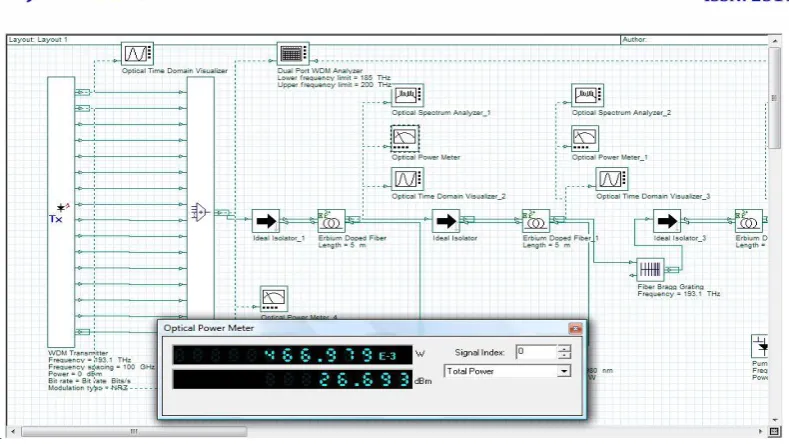
Fig: 3: Proposed System Architecture of multi stage EDFA with FBG
IV.
RESULT
Single stage EDFA
The product Optisystem is utilized to outline the EDFA in the WDM framework. The framework comprises of
16 info signals (channels), a perfect multiplexer, isolators, a pump laser, erbium doped fiber with length of 15
m, demultiplexer, photograph finder PIN, low pass Bessel channel as appeared in Figure . The contribution of
the framework is 16 evened out wavelength multiplexed motions in the wavelength locale of 193.1 Thz with100
Ghz channels dispersing. The energy of each channel is 0 dBm. The pumping at 980nm is utilized to energize
the doped molecules to a higher vitality level with 0.75 W.
In single stage EDFA case, when the signs goes through from perfect mux, and the signs which gone from
perfect mux, the perusing will on first optical power meter ( optical power meter_4). The figure 6.1
demonstrates that estimation of signs on beginning of this operation. This is the primary meter to take note of
1957 |
P a g e
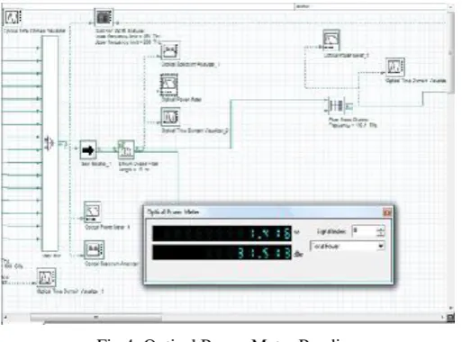
Table 1: Value of signals on each optical power meter at different distance for single stage EDFA
Fig 4: Optical Power Meter Reading
Multi Stage EDFA
The product Optisystem is utilized to plan the EDFA in the WDM framework. The framework comprises of 16
info signals (channels), a perfect multiplexer, four isolators, a pump laser, erbium doped fiber with length of 5
m, demultiplexer, photograph locator PIN, low pass Bessel channel as appeared in Figure 1. The contribution of
the framework is 16 adjusted wavelength multiplexed motions in the wavelength area of 193.1 Thz with100 Ghz
channels dividing. The energy of each channel is 0 dBm. The pumping at 980nm is utilized to energize the
doped iotas to a higher vitality level with 0.75 W. The each isolator taken after by Erbium Doped Fiber. The
first isolator (isolator_1) trailed by EDF, draw laser with recurrence of 980 nm and power 0.75 W.
In multi arrange EDFA case, when the signs goes through from perfect mux, and the signs which gone from
perfect mux, the estimation of signs will be on first optical power meter ( optical power meter_4). The figure 6.5
demonstrates that estimation of signs on beginning of this operation. This is the main meter to take note of the
estimation of transmitted flag. Additionally called likewise optical transmitter.
Table 2: Value of signals on each optical power meter at different distance for multistage EDFA S.No. Length Of
Optical Fiber
Input Power EDFA Amplifier
MW
After EDFA1
Power MW
After EDFA
2 (W)
Received
Value W
1 5KM 8.71 MW 1.419 W 1.379 W 1.384 1.096 W
2 10KM 8.71 MW 1.416 W 1.379 W 1.384 0.871W
3 15KM 8.71 MW 1.416 W 1.379 W 1.384 0.691 W
1958 |
P a g e
1
Fig 5: Optical Power Meter Reading
V.CONCLUSION
As shown above, the proposed system has been successfully implement and tested in optisystem simulation environment. As warranted, the proposed design is able to give superior signal to noise ratio (s) and noise figure (dB) as compare to single stage EDFA using with same output. As there is a significant rise in optical power as compared to single stage EDFA. Strategic placement of multistage EDFA, pre and post FBG, also enhance the some optical power input . As shown there is an average implement of dB. In noise figure and mw in terms of optical power as proved by the result.
Single Stage EDFA Result
Multi Stage EDFA Result
S.N
O.
Lengt
h
Input
power
(MW)
Receive
d power
(MW
Avg.
Gain
Avg.
Nois
e
Figur
e
Outpu
t
OSN
R
(DB)
Receive
d power
(MW)
Avg.
Gain
Avg.
Nois
e
Figur
e
Outpu
t
OSN
R
(DB)
1
5
8.71
MW
1.096 W
17.9
050
16.8
1
38.362
1.099
17.9
162
7.61
04
47.591
1
2
10
8.71
MW
0.871W
16.4
488
17.3
416
37.843
7
0.873
16.3
942
8.13
70
47.069
1
3
15
8.71
MW
0.691 W
15.0
656
17.6
629
37.523
2
0.693
15.0
751
8.46
20
46.750
0
4
20
8.71
MW
0.549 W
13.6
859
18.0
432
37.143
5
0.551
13.6
940
8.85
04
46.368
1959 |
P a g e
Table 3: Comparison between single stage and multi stage EDFA Results
After comparison we find out the difference between single stage and multi stage result, multi stage received power and output OSNR is more compare to single stage EDFA. In multi stage EDFA avg. Noise Figure is low compare to single stage EDFA and Avg. Gain is minor low. Thus all the whole experiment multi stage EDFA is give good output compare to single stage EDFA.
VI.FRUTURE
SCOPE
WDM system are the life line of modern day optical fiber network. As depicted by our work, use of multistage
EDFA in comparison to single stage. EDFA can provide for significant gains in terms of noise figure and optical
power. This improve the perform once of a WDM system considerably as this is progressing research avenue, a
lot more is required to cater the ever increasing bandwidth demand. Use of fives grating fibers can provide
highly effective dispersion compensation. Also ongoing research in optical amplifier via enhances EDFA to use
more sophisticated martial and component either than EDFA. Another research avenue is use of nanotechnology
for building loss less optical amplifier. With the gamut of these new technologies on the verge to be introduce,
we will see a lot happening in this decode.[12,13,16]
R
EFERENCES1. Tomas Ivaniga, LubosOvsenik, Jan Turan “The Four-Channel WDM System Using Semiconductor Optical Amplifier” IEEE 2016.
2. Ch. Pranavi& B. Geetha Rani “Uniform FBG as Dispersion Compensator in Optical Fiber Communications” IJIR 2017.
3. Pargat Singh&Dr.Charanjit Singh “A Carrier Generated Self Phase Modulation Reliant Rof System Employing RSOA As Modulator For Upstream RAUs And Incorporating DCF, FBG For Dispersion Compensation” IJARCS 2017.
4. P. S. Rath, Ajeet Satyam, Diwakar Mani Jha, Iftekhar Khalid “Performance Analysis of Long Fiber Optic Link using Fiber Bragg Grating for Dispersion Compensation” IJESC 2017.
5. RupinderKaur, Mandeep Singh“Analysis on Dispersion Compensation with DCF based on Optisystem-A Review” IJOES 2016.
6. Sachindev, Col.(Dr.) Suresh Kumar “Dispersion Compensation in Optical Fiber Communication using Bragg Grating” ICRISTM
2016.
7. SahilKakalia and Munish Singh “Performance Analysis of DWDM System Having 0.8- Tbps Date Rate with 80 Channels” IJST 2016.
8. B.Geetha Rani &Ch.Pranavi “DispersionCompensation In OFC Using FBG” IJERGS 2016.
9. R. K. Sethi&Dr. AdityaGoel “Performance Analysis of Optical Communication Systems using OFDM by Employing QPSK Modulation” IJRITCC 2015.
10. Jiangbing Du, Lu Li, Xinyu Fan, Qingwen Liu and Zuyuan He “Sensitivity Enhancement for Fiber Bragg Grating Sensors by Four Wave Mixing” SJTU 2015.
11. Ranjita Rout &SubhrajitPradhan&SrikantaPatnaik “Role of DCF technique for enhancing optical fiber communication System utility”
IRJET 2015.
12. AashimaBhardwaj, GauravSoni “Performance Analysis of Optical Communication System Using Fiber Bragg Grating” SSRG-IJECE
2015.
13. ManpreetKaur, HimaliSarangal “Simulation of Optical Transmission System toCompensate Dispersion Using Chirped Fiber Bragg Grating (FBG)” IJARCCE 2015.
14. TarunBansal&Mr.P.S.Bhullar “Designing High Data Rate Long Haul Optical Communication System 96 × 80 Gb/s transmission using
1960 |
P a g e
15. MulayamYadav&A.K. Jaiswal&NeeleshAgrawal&NavenduNitin “Design Performance of High Speed Optical Fiber WDM System with Optimally Placed DCF for Dispersion Compensation” IJCA 2015.