Top Launch for Higher Off-axis Electron Cyclotron Current Drive
Efficiency
Xi Chen1,*, Ron Prater1, Craig Petty1, John Lohr1, David Su1, Lang Lao1, and Vincent Chan2 1
General Atomics, P.O. Box 85608, San Diego, CA 92186-5608, USA 2
University of Science and Technology of China, Hefei, Anhui 230026, China
Abstract. Efficient off-axis current drive is crucial for economic, steady-state tokamak fusion power plants. "Top Launch" electron cyclotron current drive (ECCD) is one promising method for driving strong off-axis current to achieve the desired broad current profile for the Advanced Tokamak regime. New simulations show that by launching the electron cyclotron (EC) waves downwards (or upwards) nearly parallel to the resonance plane with a large toroidal steering, higher current drive efficiency can be obtained at large radii owing to the large Doppler shift, wave-particle interactions on HFS of the plasma, and the long absorption path. Implementations on CFETR and DIII-D are simulated identifying clear benefits and optimal configurations. The design of a prototype test being installed on DIII-D is presented, which will experimentally validate whether top launch ECCD can be an improved efficiency current drive technique for future fusion reactors.
1 Introduction
Studies of many tokamak reactors have shown that off-axis current drive is a requirement for a steady-state device in the Advanced Tokamak (AT) regime [1, 2, 3, 4]. The off-axis current drive needs to be efficient because, if the efficiency is too low, 1) the required current drive to sustain the plasma configuration, i.e., the elevated qmin in the ‘high-qmin’ scenario might not be attainable due to limited source power; or 2) it will need too much power, preventing a net electricity goal or increasing cost of electricity since fusion gain is linearly proportional to current drive efficiency Q=Pfus/Paux~ζCD.
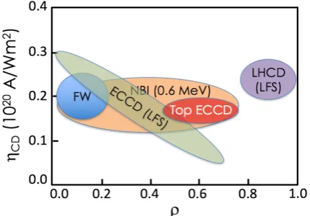
A suitable method of off-axis current drive with the efficiency and location required for economical AT reactors has yet to be demonstrated. While neutral beam current drive (NBCD) can be an efficient non-inductive current drive scheme, neutral beams are large objects that are challenging to make mechanically consistent with other systems in the tokamak reactor environment (e.g., the vacuum vessel, breeding blanket, neutron shielding, etc.). The large tangency and larger port size needed to achieve off-axis current drive increases the challenges. In addition, NBCD is efficient only at high voltage (i.e., 1MeV) and long pulse high voltage beam development is very challenging [5, 6]. Radio frequency (RF) wave injection is another common non-inductive current drive technique. Among these techniques, lower hybrid current drive usually has the highest efficiency. However, in fusion plasma conditions, the absorption of lower hybrid waves is so strong that it usually drives current only in the pedestal region (ρ>0.85). Fast wave
has moderate efficiency but is core localized, plus there are concerns about the presence and survival of the antenna in the reactor environment. Current drive using electron cyclotron waves [7] does not require the antenna structures be placed near the plasma since the waves propagate in vacuum. ECCD launched from the low field side (LFS) can drive current at ρ ~ 0.5-0.7 in reactor-like plasmas but it has low efficiency due to electron trapping in the magnetic well. Increasing the applied wave frequency can improve the current drive efficiency by moving the primary resonance layer to the high field side (HFS) where the impact of trapped particles is less, but parasitic second (or third) harmonic absorption can become problematic.
Several new off-axis current drive techniques have been proposed, such as ‘Helicon’ or ‘Whistler’ waves (ultra-high-harmonic fast wave), which is predicted to have excellent penetration for high density and high temperature plasmas, as well as high field side (HFS)-launch lower Hybrid (slow wave) current drive that is predicted to dramatically reduce plasma-wall (+antenna) interaction issues, improve wave coupling and penetration, and result in a current profile better suited for steady-state scenarios than conventional outside-launch lower hybrid. More details on these two techniques are given in Ref. [8].
The development and qualification of physics and technologies that deliver off-axis current drive (CD) with the profile and high efficiency under reactor-like conditions needed to achieve high stability and high overall energy gain will greatly enhance steady-state fusion power plants. This work presents the modeling investigation and planned experimental validation of a non-standard ECCD technique – top launch ECCD. Comparisons of top launch and conventional outside launch ECCD modelled for DEMO [9] and FNSF-AT [10] suggest that the top launch approach can substantially increase the interactions of EC waves with higher energy electrons and thus the ECCD efficiency at mid-radius. We consistently find 35% or more improvement in ECCD efficiency for CFETR [11] baseline scenario and even higher increases for some cases on the DIII-D tokamak. The concept of top launch ECCD scheme is described in section 2.1. Its application for reactors is illustrated in section 2.2 using CFETR as an example and its experimental test planned on DIII-D tokamak is presented in section 2.3 followed with summary in Section 3.
2
Top launch ECCD
Electron cyclotron current drive (ECCD) is based on production of anisotropic electron resistivity resulting from selective heating of electrons traveling in one toroidal direction [12]. These accelerated electrons undergo less collisions and contribute more to the toroidal current than their unheated counterparts traveling in the opposite direction.
Top launch ECCD uses electron cyclotron waves injected from top (or bottom) of the vessel at a major radius less than the plasma axis, in a nearly vertical plane with a large toroidal steering, to achieve higher current drive efficiency. The launch geometry allows more selective heating so that the wave energy is preferentially damped on high energy electrons.
2.1 Why does top launch give higher ECCD efficiency than conventional outside launch?
To maximize the ECCD efficiency, one would want to 1) have the EC waves interact with only high energy electrons since they are less collisional; 2) ensure enough interactions such that the wave energy is fully absorbed since there are fewer high energy electrons. The top
launch ECCD approach achieves this through the combination of the launch location and steering geometry which allows the EC waves to stay close, but not too close, to the cold resonance layer, and stay there for longer time. The wave energy is almost all damped on these high energy electrons.
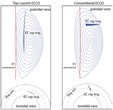
In the top launch concept, the EC wave is launched from the top or bottom of the tokamak on the high field side (HFS) of the magnetic field axis and nearly parallel to the primary cold resonance layer, whereas in the conventional ECCD concept the wave is injected from the low field side (LFS), on or off the outer midplane and towards the cold resonance. Another unique feature of the top launch concept is that the EC wave is steered with a much larger toroidal angle than for LFS launch. Some features of the top launch ECCD scheme that differ from the conventional ECCD scheme are shown in Fig. 2, where the wave trajectories of these two schemes are compared in the poloidal and toroidal planes. In both examples, the ECCD deposition profile peaks at ρ~0.55 and the primary resonance is fundamental O-mode.
The physics features that lead to this increase of ECCD efficiency using top launch ECCD concept are as follows:
- Stronger toroidal steering forces a larger Doppler shift, which benefits current drive.
Electron cyclotron waves can be absorbed by electrons with cyclotron frequency satisfying:
𝜔=𝑙Ω𝑒
𝛾 +𝑘∥𝜐∥ (1)
where 𝜔 is the frequency of applied EC wave, Ω𝑒 is the electron cyclotron frequency, l is the harmonics, 𝛾 is the relativistic factor, 𝑘∥ and 𝜐∥ are 𝑘�⃑ and velocity parallel to 𝐵�⃑, 𝑘∥𝜐∥ gives the Doppler shift. The wave absorption occurs when the difference between 𝜔 and the local Ω𝑒 is nulled by the Doppler shift. If the frequency difference remains large because the wave trajectory does not reach
the cold resonance, then the wave energy is damped on faster, less collisional electrons that give a higher CD efficiency.
Fig. 3 compares the power absorption and the frequency difference between 𝜔 and the local Ω𝑒 along the ray trajectory for the two cases shown in Fig. 2. It shows that the frequency difference in the conventional LFS ECCD is rapidly decreasing and relatively small for the deposition region, but it is much larger and nearly constant along the whole ray trajectory for top launch ECCD which means the wave/particle interactions stay in high energy electrons (larger 𝜐∥).
- The wave trajectory is nearly parallel to the resonance layer, approaching the resonance much more slowly than the more perpendicular injection of the conventional LFS launch, which results in a long absorption path. As is illustrated in Fig. 3, the absorption path for top launch is ~20 times that of LFS launch. Although the density of high-energy electrons selected by the large Doppler shift is small, the long path enables sufficient wave interaction with these more energetic electrons to damp all of the EC wave power.
- The wave-plasma interactions take place on the HFS of the flux surface where the effect of mirror trapping of current-carrying electrons is greatly reduced [13, 14].
Although top launch ECCD approach is also limited to cut off density as the conventional outside launch, it has better accessibility than outside launch at high density benefit from the long absorption path.
2.2 Top launch ECCD scheme for reactors
As an example of how the top launch ECCD scheme can work in reactors, this section models the ECCD using the equilibrium and kinetic profiles of the China Fusion Engineering Test Reactor (CFETR) [11] baseline
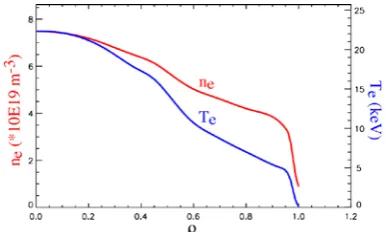
scenario. CFETR is designed to operate with a large bootstrap fraction, approaching 80%, but non-inductive support of the remaining current is still required. The parameters of the machine are major and minor radius of the machine R0=5.7m and a=1.6m, plasma current Ip = +10 MA, toroidal magnetic field BT = +5T (Ip and BT are in the same direction), central density ne(0) = 7.49×10¹⁹/m3, and central temperature Te(0) = 23.33 keV (Fig. 4).
Figure 4: Equilibrium density and temperature profiles of CFETR baseline scenario
A top launch ECCD scheme can be a valuable approach to increase the off-axis current drive in CFETR. Using the applied EC frequency and launch location as free parameters, a systematic study is carried out to identify the conditions for optimum off-axis ECCD profile with high dimensionless current drive efficiency [15] at specified locations (needed to reduce power consumption). Several launch locations and frequencies are studied as illustrated in Fig. 5. For a given launch location and frequency, the launching polar and azimuthal angles are scanned.
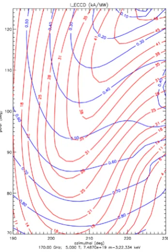
The optimal injection angle is determined by which the I_ECCD is highest at the target deposition location. The polar and azimuthal angles are the Euler angles for EC wave launch: the polar angle is that between the EC ray and the vertical z-axis, roughly representing the poloidal steering; the azimuthal angle is the angle between the plane containing z and the EC ray away from a reference plane, roughly representing the toroidal steering. Figure 6 shows such a scan from the LFS outside launch and the optimal injection is determined as (Polar, Azimuthal) = (93.9, 208.8) degree. A sample of the results calculated using the TORAY ray tracing code [16, 17] is listed in Table 1 where the optimal aiming (polar and azimuthal angles) (not shown) is different for different launch locations and/or frequencies. The CD efficiency 𝜁𝑒𝑒is derived from normalizing the standard theoretical efficiency (Jec/Pec) to nevth/nkTνe [15].
𝜁𝑒𝑒=𝑒
3
𝜀02�
𝐼𝑒𝑒𝑅𝑛𝑒
𝑃𝑒𝑒𝑘𝑇𝑒�= 3.27
𝐼𝑒𝑒(𝐴)𝑅(𝑚)𝑛19(𝑚−3)
𝑃𝑒𝑒(𝑊)𝑇𝑒(𝑘𝑒𝑘) (2)
Using the dimensionless current drive efficiency allows comparison with other machines. Table 1 shows that a top launch ECCD scenario with ~190GHz launching from the top of the vessel (R=5.45 m, z=4.0 m) can drive current >30% more efficiently than conventional LFS launch at mid-radius.
Figure 5:Various launch locations and frequencies studied for high off-axis ECCD efficiency on CFETR.
Figure 6: Contour plot of the EC driven current from a scan of launching polar and azimuthal angles, the level of I_ECCD (red) at each radial location (blue). EC wave launched from the LFS outside launch at 170GHz in CFETR baseline scenario.
Table 1: Sample of peak ECCD efficiency from LFS vs Top launch ECCD for CFETR*
Launch location
(R, Z) (meter)
Applied EC frequency
(GHz)
ρ ~ 0.5
ECCD (kA/MW)
CD efficiency
LFS Launch
(7.20, 2.04)
170 35.4 0.275
140 30.0 0.235
190 36.0 0.284
Top Launch
(5.45, 4.0)
190 46.8 0.370
194 47.9 0.378
192 47.0 0.372
* off-axis NBI current drive is about 100kA/MW with 0.6MeV NB for this scenario
2.3 Top launch ECCD for DIII-D tokamak
2.3.1 Systematic physics feasibility study
In preparation for a physics test of top launch ECCD on DIII-D, a physics scoping study similar to that for CFETR has been done. The ECCD efficiencies at mid-radius from various launch locations are evaluated at the two applied frequencies (110GHz and 117.5GHz, 2nd harmonic X-mode) that are available on DIII-D. The scoping study is performed using the equilibrium and kinetic profiles from six DIII-D discharges and one modelled DIII-D steady state discharge with the majority being high qmin AT scenarios in double null plasma shape (investigated launch locations and the plasma shapes are illustrated in Fig. 7). Compared to the existing LFS launch, the TORAY ray tracing code found 50% to 100% higher off-axis ECCD efficiency from top launch in some of these plasmas (examples shown in Table 2). For optimized launch angles, the ECCD efficiency generally differs less than 10% between 110 GHz or 117.5 GHz.
Table 2: Sample of peak ECCD efficiency from LFS vs Top launch ECCD for DIII-D*
Figure 7:The launch locations and plasma shapes used in the physics feasibility study of Top launch ECCD on DIII-D
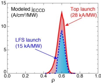
These improvements in off-axis ECCD efficiency accrued from top launch on DIII-D have also been confirmed by the quasi-linear Fokker-Planck CQL3D code [18]. Figure 8 shows an example where the current drive efficiency nearly doubles using top launch over the LFS launch. CQL3D results also reveal a modest (~10%) quasilinear increases in ECCD efficiency for top launch as the power is scanned from 0.01MW to 3MW in the top the launch ECCD scheme while no quasilinear increase is observed for outside launch scheme.
Figure 8:Driven current density profile for top launch and LFS launch for a DIII-D discharge modeled using CQL3D
2.3.2 Prototype fixed-injection top launch ECCD system on DIII-D
A prototype top launch ECCD system is being planned on the DIII-D tokamak to test the top launch concept, establish physics basis for future burning plasma devices and advance the AT program of DIII-D at lower cost. Due to the limitations in the existing port structure, the prototype top launch launcher (Fig. 9) will have a fixed injection angle from a given port location (port 7 shown in Fig. 7). A waveguide switch will be used to connect
an existing gyrotron to either the LFS or the top launcher.
Figure 9: Preliminary design of the prototype fix-injection top launch launcher
Top launch ECCD scheme is sensitive to launching angle. Deviation of 5 degrees from the optimal aiming in some direction could lead to large reduction in the current drive efficiency or inaccessible to the desired location. Therefore, the accuracy of aiming of the fixed-injection launcher is set to 1 degree which limits any reduction in current drive efficiency and ECCD to be within 15% and 20% respectively and the movement of the deposition location to be within ∆ρ = 0.03.
2.3.3 Additional parameters to tune the ECCD and efficiency with fixed-injection
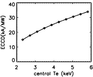
Figure 10: ECCD driven from top launch increases with the electron temperature
ECCD from the conventional outside launch has been shown to increase with electron temperature, and a similar feature is also observed for top launch ECCD as illustrated in Figure 10. Since the larger effect of the electron temperature is removed by the normalization in Eq (2), it has less effects on the dimensionless current drive efficiency which mainly comes in through the quasilinear effect. Thus, increasing the electron temperature at fixed-injection angle increases the driven ECCD which can improve the signal to noise ratio for the measurements.
3 Summary
Steady-state operation in a cost effective fusion power plant requires efficient off-axis current drive but present approaches have limitations. Simulations show that significantly higher current can be driven at mid-radius using the top launch ECCD approach compared to conventional low field side launch. To verify the physics basis and develop the engineering of this technique, a prototype top launch ECCD system is being designed and planned to operate on the DIII-D tokamak in 2019 which, if successful, will help to advance the AT program of DIII-D at lower cost since more off-axis current will be driven with the same gyrotron power.
The top launch ECCD scheme is sensitive to changes in operating conditions, i.e., magnetic field and EC wave injection angle. As the proof-of-principle prototype top launch ECCD system on DIII-D will have fixed injection, the deposition location will be controlled mainly through changing the magnetic field strength, plasma shape and electron temperature. The top launch ECCD test can be done with either a 110GHz or 117.5GHz gyrotron, and use of a waveguide switch between the outside LFS and top launchers means that a dedicated gyrotron is not needed. This prototype top launch system will also allow us to test the hot plasma effect which is not included in the simulation.
The Work supported in part by DE-FC02-04ER54698 and GA-USTC contract AHCC15B11459A, DIII-D data shown here can be obtained in digital format at https://fusion.gat.com/global/D3D_DMP. This report
was prepared as an account of work sponsored by an agency of the United States Government. Neither the United States Government nor any agency thereof, nor any of their employees, makes any warranty, express or implied, or assumes any legal liability or responsibility for the accuracy, completeness, or usefulness of any information, apparatus, product, or process disclosed, or represents that its use would not infringe privately owned rights. Reference herein to any specific commercial product, process, or service by trade name, trademark, manufacturer, or otherwise does not necessarily constitute or imply its endorsement, recommendation, or favoring by the United States Government or any agency thereof. The views and opinions of authors expressed herein do not necessarily state or reflect those of the United States Government or any agency thereof.
References
1. T.S. Taylor, et al., Plasma Phys. Control. Fusion 36, B229 (1994)
2. F. Najmabadi, et al., FED 38, 3 (1997)
3. A.C.C. Sips, et al., Phys. Plasma 22, 021804 (2015) 4. V.S. Chan, et al., Nucl. Fusion 46, 451(2006) 5. R.S. Hemsworth, et al., New J. Phys. 19, 025005
(2017)
6. P. Sonato, et al., New J. Phys. 18, 125002 (2016) 7. R. Prater, Phys. Plasma 11, 2349 (2004)
8. R.I. Pinsker, et al., this conference
9. E. Poli, et al., Nucl. Fusion 53, 013011 (2013) 10. A. M. Garofalo, et al., Nucl. Fusion 54, 073015
(2014)
11. Y.X. Wan, et al., Overview of the present progresses and activities on the Chinese fusion engineering test reactor (preprint : IAEA Fusion Energy Conf., Kyoto, Japan, 2016)
12. N.J. Fisch, A.H. Boozer, Phys. Rev. Lett. 45, 720 (1980).
13. G. Schmidt, Physics of High Temperature Plasmas, p 22 (Academic, New York, 1966)
14. C.C. Petty, et al., Nucl. Fusion 43, 700 (2003) 15. T.C. Luce, et al., Phys. Rev. Lett. 83, 4550 (1999) 16. K. Matsuda, IEEE Trans. Plasma Science 17, 6
(1989)
17. Y.R. Lin-Liu, V.S. Chan and R. Prater, Phys. Plasma 10, 4064 (2003)