STRAIN TRANSFER FUNCTION IN FLEXIBLE
PAVEMENTS
Gobin Engleng
Department of Civil Engineering, Parvatibai Genba Moze College of Engineering,
Pune,Wagholi, (India)
ABSTRACT
Structural failure of anflexible pavement is primarily caused due to fatigue and rutting failures. To measure
fatigue performances, the critical horizontal tensile strain (
t) at the bottom of flexible layer is popularly used in the mechanistic-empirical (M-E) pavement design process. However, the computation of
t in a 3-D multilayered pavement structure with distributed loading is a complex phenomenon. This paper attempts topresent simple strain transfer functions for estimation of
t, considering 3-D nonlinear analysis of flexible pavements. The transfer function is validated and found adequate in prediction of
t. Degree of accuracy has also beenjustified statistically. ABAQUS software is used for analysis of pavement structures.Keywords: Flexible Pavement, Strain, Fatigue,3-D, Nonlinear
I INTRODUCTION
II BACKGROUND
Current practice of flexiblepavements design, popularlyknown as Mechanistic-Empirical (M-E) designmethod is followed in various guidelines[1-7]. Fatigue and rutting are considered as two primary modes of structural failures. Normally, the failure criteria adopted as 20% of surface cracks area in case of fatigue and 20mm of rut depth in case of rutting failure.The numbers of load repetitions till failure is recorded as pavement life. Fatigue life (
N
f ) isempirically correlated with the critical strain parameter of the section. A general form of fatigue equation may be expressed as given in Eq.(1).3 2
1 1
1
1
k kt f
E
k
N
(1)where,
N
f is the fatigue life;
t is the initial critical horizontal tensile strain at the bottom of flexible layer;E
1is the initial stiffness of flexible material; and,
k
1,k
2, andk
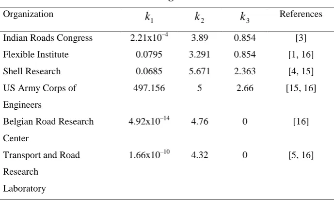
3are regression constants.Different literatures suggest different values forthese parameters. Some of them are listed in Table 1.Table 1. Parameters of fatigue equation adopted in M-E pavement
design.
Organization
1
k
k
2k
3 ReferencesIndian Roads Congress 2.21x10⁻⁴ 3.89 0.854 [3]
Flexible Institute 0.0795 3.291 0.854 [1, 16]
Shell Research 0.0685 5.671 2.363 [4, 15]
US Army Corps of Engineers
497.156 5 2.66 [15, 16]
Belgian Road Research Center
4.92x10⁻¹⁴ 4.76 0 [16]
Transport and Road Research
Laboratory
1.66x10⁻¹⁰ 4.32 0 [5, 16]
It may be mentioned that
N
f and
t shall be in respect of same loading conditions (say, standard axle load of 80kN). ReplacingN
f by the total number of traffic repetitions to be sustained during the design life, the maximum allowable
tvalue can be determined from Eq.(1). Accordingly, comparing these strains values with the computed
tas obtained from structural analysis, the thicknesses of the design layer(s) can be decided iteratively.been adopted by various researchers [8-12] for numerical analysis of pavement structures. In the present work also, ABAQUS is used to model and analyze the flexible pavements,and it is discussed in the next section.
III MODELING OF PAVEMENT STRUCTURE
Normally, anflexible pavement structure contains 3 to 4 number of load bearing layers. In this study, a 3-layred and a 4-layred pavement has been modeled as 3-D nonlinear elastic structure with finite boundaries. A 3-layred pavement section is shown in Figure 1. FEM based analysis of the pavement is carried out in the ABAQUS environment. Eight noded linear brick elements with reduce integration (C3D8R) is used in analysis, which considers only one integration point at the middle. This element has ability to reduce the computational effort without significant affect on the accuracy.Each element is considered with three degrees of freedom (i.e. displacement in X,Y and Z-directions). Pavement section of 3.5m×10m with end conditions of zero displacement in transverse (-X) and longitudinal (-Y) directions, and fixed end at the bottom of subgrade are used, including rough interface between two layers.A fine mesh of 4.9cm x 7.2cm for flexible layer, and coarse mesh of 9.8cm × 14.24cm for granular and subgrade layers are chosen. This is depicted in Figure 1. The analysis of pavement structureshas been discussed in the next section.
Figure 1. 3-layred flexible pavement structure.
IV PAVEMENT ANALYSIS AND MODEL DEVELOPMENT:
In M-E pavement design process, the fatigue performance is predicted based on initial critical horizontal tensile strain (
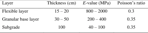
t) at the bottom of flexible layer. Table 2 shows the layers information for a 3-layred pavement section. To represent the different cases, possible ranges of each parameter has been considered as shown in the table. Poisson‟s ratio is taken as constant due to negligible effect (Huang, 2004). A uniformly distributed standard dual wheel load of 20kN with tyre pressure of 0.7MPa over its contact area has been adopted for all the cases.Table 2. Layers information used for 3-layred pavement analysis.
Layer Thickness (cm) E-value (MPa) Poisson‟s ratio
Flexible layer 15 – 20 800 – 2000 0.3
Granular base layer 30 – 50 200 – 400 0.35
For different combinations of layers input as given in Table 2, the strain parameter (
t) are computed through ABAQUS. Figure 2 shows the strains contour in one case obtained from the ABAQUS analysis. The variations of
t with flexible modulus (E
1) is shown in Figure 3. Negative value indicates compression. Similarly,t
variation with other variable parameters is also presented in Figures (4) – (7).Figure 2.Contour plots of tensile strain in 3-layered pavement structure.
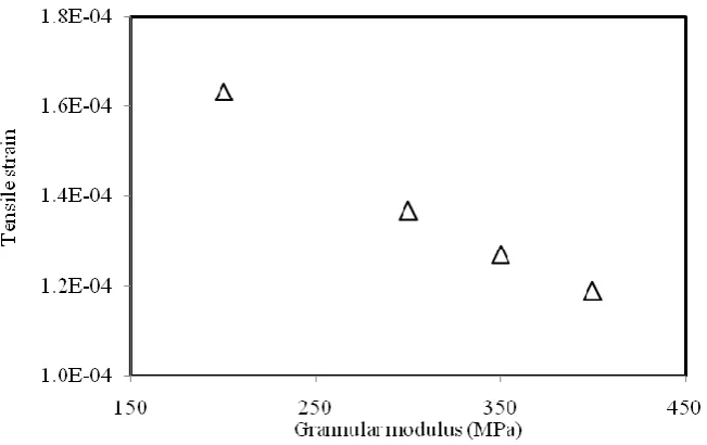
Figure 4. Strain variations with modulus (E
2) of granular layer.
Figure 5. Strain variations with modulus (E
3) of subgrade layer.
Figure 7. Strain variations with granular layer (h
2) thickness.
From Figures (3) – (7), it is observed that
tparameter isclosely correlated with the independent parameters. Combining all the independent variablestogether, the nonlinear multivariable best fit curves for a 3-layred pavement structure are derived using EViews as given in Eq.(2).)
ln(
)
ln(
)
ln(
)
ln(
)
ln(
1 3 2 4 3 5 1 6 22
1
f
E
f
E
f
E
f
h
f
h
f
t
(2)where,
E
1,E
2 andE
3 are the moduliiof flexible, granular and subgrade layer respectively in MPa;h
1 and2
h
are the thicknesses of flexible and granular layer respectively in cm, andf
iare the model parameters. Thei
f
parameters are tabulated in Table 3. From Table 3, it is seen that theE
3 andh
2 parameters are notsignificant to
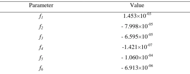
t, as compare to other parameters. This is what it is expected also.Table 3. Parameters of strain model of 3-layredflexible pavement.
Parameter Value
f1 1.453×10-03
f2 - 7.998×10-05
f3 - 6.595×10-05
f4 -1.421×10
-07
f5 - 1.060×10
-04
f6 - 6.913×10-06
Table 4. Statistical parameters of the strain model for 3-layredflexible pavement.
Parameter Tensile strain model
R-squared 0.995
Adjusted R-squared 0.994
Std. error of regression 1.95×10-06
Sum squared residue 1.14×10⁻¹⁰
F-statistic 1234
Prob. of F-statistic 0.000
In a similar way, the strain transfer functions are also developed for 4-layered pavement structures viz. flexible, granular base, granular sub-base and subgrade layers, and found that the strain parameter (
t) is closely correlated with the structural input parameters. The nonlinear multivariable best fit curves for
t in 4-layred pavement structure are derived as given in Eq.(3).)
ln(
)
ln(
)
ln(
)
ln(
)
ln(
)
ln(
)
ln(
1 3 2 4 3 5 4 6 1 7 2 8 32
1
f
E
f
E
f
E
f
E
f
h
f
h
f
h
f
t
(3)where,
E
1,E
2,E
3 andE
4are the modulii of flexible, granular base, granular sub-base and subgrade layerrespectively in MPa;
h
1,h
2 andh
3are the thicknesses of flexible, granular base and granular sub-base layerrespectively in cm; and
f
i, are the model parameters. Thef
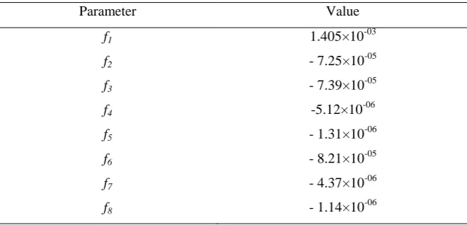
i parameters are tabulated in Table 5.Table 5. Parameters of strain model for 4-layreda flexible pavement.
Parameter Value
f1 1.405×10-03
f2 - 7.25×10-05
f3 - 7.39×10-05
f4 -5.12×10-06
f5 - 1.31×10-06
f6 - 8.21×10-05
f7 - 4.37×10-06
f8 - 1.14×10-06
Table 6. Statistical parameters of the strain model for4-layredflexible pavement.
Parameter Tensile strain model
R-squared 0.999
Adjusted R-squared 0.999
Std. error of regression 3.93×10-07
Sum squared residue 5.10×10⁻¹²
F-statistic 7232
Prob. of F-statistic 0.000
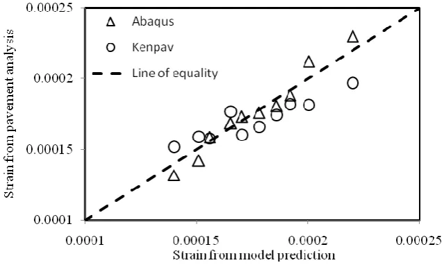
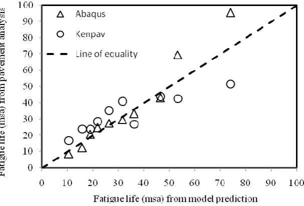
Further, it is attempted to validate the developed models using separate sets of input data, through ABAQUS and KENPAVE analysis as well. This is illustrated in the next section.
V VALIDATION
In order to validate the statistical strains transfer functions, different flexiblepavement sections are analyzed considering separate sets of input data. The strain (
t) values are evaluated using both ABAQUS and KENPAVE analysis program. The comparison of
tvalue calculated from pavement analysis and the developed strain model is shown in Figure 8. To compare the strain transfer functions in terms of the fatigue life (N
f ) and prediction, a comparison ofN
f in million standard axles (msa) is presented in Figure 9.Regression constants of the fatigue equation are adopted as per TRL models (Huang, 2004). Thus, from Figure 8 or Figure 9 it may be concluded that the model prediction is sufficiently good as that of ABAQUS or KENPAVE analysis programs.VI CONCLUSIONS
Simple strain transfer function for horizontal tensile strain (
t)in flexible pavements has been developed and presented in the paper. The proposed
tfunction is validated and found adequate in prediction. Statistically also, this transfer function is tested and found confident. Thus, the proposed strain model can easily be adopted for fatigue life estimation in the pavement design process, and can be avoided complex analysis and high computational effort.Also, to incorporate the reliability or probability in pavement design, one can easily know the distribution of
tfor any given distributions of their input parameters. For example, the
tparameter would follow normal distribution, in case the inputsE
i andh
i in the strain functions (Eqs. (2) and (3)) are log-normally distributed.Towards M-E fatigue design of flexible pavements, this work focuses on establishing an acceptable statistical correlation between the strain parameter (
t) and layers informationin 3-layred and 4-layred pavement structures. However, they have few limitations like the effect of moving loads, visco-elastic behavior etc are not accounted and are recommended for further studies.REFERENCES
[1] Flexible Institute (AI). Thickness design - flexible pavements for highways and streets, Manual Series No.1, 9th Edition, The Flexible Institute, Lexington, Ky, USA, 1999.
[2] French.,French design manual for pavements structures, Guide Technique, LCPC and SETRA, Francaise, 1997.
[3] Indian Roads Congress (IRC).,Guidelines for the design of flexible pavements, IRC: 37-2012, 3rd Revision, The Indian Roads Congress, New Delhi, India, 2012.
[4] Shell., Shell pavement design manual – flexible pavement and overlays for road traffic, Shell International Petroleum Company Limited, London, UK, 1978.
[5] Transport Research Laboratory (TRL).,A guide to the structural design of bitumen-surfaced roads in tropical and sub-tropical countries. Overseas Road Note 31, 4th Edition, Overseas Center, TRL, London, 1993.
[6] National Cooperative Highway Research Program (NCHRP)., Mechanistic-empirical design of new & rehabilitated pavement structures, NCHRP Project 1-37A, Transportation Research Board, Washington, D.C, 2004.
[7] Austroads. Pavement design, Austroads, Sydney, Australia, 2004.
[8] Hadi, M.N.S., and Bodhinayake, B.C., “Non-linear finite element analysis of flexible pavements”,
Advances in Engineering Software, Elsevier, Vol.34, pp.657-662, 2003.
[9] Kuo, C.M., and Chou, F.J., “Development of 3-D finite element model for flexible pavements, Journal of the Chinese Institute of Engineers, 27(5), pp.707-717, 2004.
[10] Helwany, S., Dyer, J., and Leidy, J., “Finite-element analyses of flexible pavements”, Journal of Transportation Engineering, ASCE, 124(5), pp.491–499, 1998.
[11] Lacey, G., Thenoux, G., and Rodríguez-Roa, F., “Three-dimensional finite element model for flexible pavement analysis based on field modulus measurements”, The Arabian Journal for Science and Engineering, Vol. 33, No. 1B, pp.65-76, 2008.
[12] Rahman, M.T., Mahmud, K., and Ahsan, S., "Stress-Strain characteristics of flexible pavement using Finite Element Analysis", International Journal of Civil and Structural Engineering, 2(1), pp.233-240, 2011.
[13] Chandra, S., Viladkar, M.N., and Nagrale, P.P., “Mechanistic approach for fiber-reinforced flexible pavements”, Jr. of Transportation Engineering, ASCE, 134(1), pp.15-23, 2008.
[14] Das, A., and Pandey, B.B., “Mechanistic-empirical design of bituminous roads: an Indian perspective”, Jr. of Transportation Engineering, ASCE, 125(5), pp.463-471, 1999.
[15] Behiry, A.E.A.M., “Fatigue and rutting lives in flexible pavement”, Ain Shams Engineering Journal, Ain Shams University, Vol.3, pp.367–374, 2012.