Installing and Using the
STEP 7-Micro/WIN Version 2.0
Software
2
Getting Started with a Sample
Program
3
Basic Concepts for
Programming the CPU 210
4
Instruction Set
5
Appendix
CPU 210 Data Sheets
A
Special Memory (SM)
B
Error Handling and Error Codes
C
Converting STEP 7-Micro/DOS
Files to STEP 7-Micro/WIN Files
D
Execution Times for STL
Instructions
E
CPU 210 Order Numbers
F
Index
C79000-G7076-C235-01
S7-200
Programmable Controller,
CPU 210
System Manual
SIMATIC
!
Danger
indicates that death, severe personal injury or substantial property damage will result if proper precautions are not taken.!
Warning
indicates that death, severe personal injury or substantial property damage can result if proper precautions are not taken.!
Caution
indicates that minor personal injury or property damage can result if proper precautions are not taken.Note
draws your attention to particularly important information on the product, handling the product, or to a particular part of the documentation.
The device/system may only be set up and operated in conjunction with this manual.
Only qualified personnel should be allowed to install and work on this equipment. Qualified persons are defined as persons who are authorized to commission, to ground, and to tag circuits, equipment, and sys-tems in accordance with established safety practices and standards.
Note the following:
!
Warning
This device and its components may only be used for the applications described in the catalog or the technical description, and only in connection with devices or components from other manufacturers which have been approved or recommended by Siemens.This product can only function correctly and safely if it is transported, stored, set up, and installed correctly, and operated and maintained as recommended.
SIMATICR and SINECR are registered trademarks of SIEMENS AG.
Third parties using for their own purposes any other names in this document which refer to trademarks might infringe upon the rights of the trademark owners.
We have checked the contents of this manual for agreement with the hardware and software described. Since deviations cannot be precluded entirely, we cannot guarantee full agreement. However, the data in this manual are reviewed regularly and any necessary corrections included in subsequent editions. Suggestions for improvement are welcomed.
Technical data subject to change.
E Siemens SE&A 1997 Disclaimer of Liability Copyright E Siemens SE&A 1997 All rights reserved
The reproduction, transmission or use of this document or its contents is not permitted without express written authority. Offenders will be liable for damages. All rights, including rights created by patent grant or registration of a utility model or design, are reserved.
Siemens Energy & Automation, Inc. 3333 Old Milton Parkway
Alpharetta, GA 30202
Qualified Personnel
Correct Usage
Purpose
The CPU 210 is an addition to the S7-200 series micro-programmable logic controllers (Micro PLCs). Its compact design, low cost, and powerful instruction set make the CPU 210 a perfect solution for controlling small applications. The selection of voltage options provides you with the flexibility you need to solve your automation problems.
The SIMATIC S7-200 CPU 210 Programmable Controller System Manual provides information about installing and programming the CPU 210 and the program development station (PDS 210). This manual also includes descriptions and examples for the
programming instructions, typical execution times for the instructions, and the data sheets for the CPU 210 and related equipment.
Audience
This manual is designed for engineers, programmers, installers, and electricians who have a general knowledge of programmable logic controllers.
Scope of the Manual
The information contained in this manual pertains in particular to the following products:
S
CPU 210 and the PDS 210S
STEP 7-Micro/WIN version 2.0 programming softwareHow to Use This Manual
If you are a first-time (novice) user of S7-200 Micro PLCs, you should read the entire manual. If you are an experienced user, refer to the table of contents or index to find specific
information.
The manual is organized in the following topics:
S
“Installing the CPU 210” (Chapter 1) provides an overview of some of the features of the equipment and the procedures, dimensions, and basic guidelines for installing the CPU 210.S
“Installing and Using the STEP 7-Micro/WIN Version 2.0 Software” (Chapter 2) describes how to install the programming software. It also provides a basic explanation about the features of the software.S
“Getting Started with a Sample Program” (Chapter 3) helps you enter a sample program, using the STEP 7-Micro/WIN software.S
“Basic Concepts for Programming the CPU 210” (Chapter 4) provides information about how the CPU 210 processes data and executes a program.S
“Instruction Set” (Chapter 5) provides explanations and examples of the programming instructions used by the CPU 210.Additional information (such as the equipment data sheets, error code descriptions and execution times) are provided in the appendices.
Additional Assistance
For assistance in answering technical questions, for training on this product, or for ordering, contact your Siemens distributor or sales office.
1.1 Product Overview. . . 1-2 Equipment Requirements . . . 1-2 Features of the CPU 210 . . . 1-3 1.2 Pre-installation Considerations . . . 1-4 Installation Configuration. . . 1-4 Clearance Requirements for Installing a CPU 210 . . . 1-4 DIN Rail Requirements . . . 1-5 Panel-Mounting Dimensions. . . 1-5 1.3 Installing a CPU 210 . . . 1-6 Mounting a CPU 210 on a Panel . . . 1-6 Installing a CPU 210 on a DIN Rail . . . 1-6 Installing a CPU 210 in a Panel Box . . . 1-7 1.4 Installing the Field Wiring . . . 1-8 General Guidelines . . . 1-8 Grounding and Circuit Referencing Guidelines for Using Isolated Circuits . . . 1-9 Using the Optional Field Wiring Connector . . . 1-10 Guidelines for AC Installation. . . 1-10 Guidelines for DC Installation. . . 1-10 1.5 Using Suppression Circuits. . . 1-12 Protecting DC Transistors. . . 1-12 Protecting Relays Controlling DC Power . . . 1-12
2
Installing and Using the STEP 7-Micro/WIN Version 2.0 Software
2.1 Installing the STEP 7-Micro/WIN Version 2.0 Software . . . 2-2 Pre-installation Instructions. . . 2-2 Installation Instructions for Windows 3.1 . . . 2-2 Installation Instructions for Windows 95 . . . 2-2 Troubleshooting the Installation . . . 2-2 2.2 Establishing Communication with the PDS 210 . . . 2-3 Connecting Your Computer to the PDS 210 for PPI Communications. . . 2-3 Setting Up the Communications Parameters. . . 2-4 2.3 Configuring the Preferences for STEP 7-Micro/WIN. . . 2-5 2.4 Creating and Saving a Project . . . 2-6 Creating a New Project . . . 2-6 Saving a Project . . . 2-6
2.5 Creating a Program . . . 2-7 Entering Your Program in Ladder . . . 2-7 Entering Your Program in Statement List . . . 2-8 Compiling the Program . . . 2-8 Viewing a Program in Ladder or Statement List . . . 2-9 2.6 Downloading A Program . . . 2-10 Downloading the Program to the PDS 210 . . . 2-10 Copying Your Program to the Memory Cartridge . . . 2-11 Transporting the Program to the CPU 210. . . 2-11 2.7 Using Symbolic Addressing . . . 2-13 Guidelines for Entering Symbolic Addresses. . . 2-13 Starting the Symbol Table Editor . . . 2-13 Editing Functions within the Symbol Table. . . 2-14 Sorting Table Entries . . . 2-14 Displaying the Symbolic Addresses . . . 2-14 2.8 Using the Status Chart . . . 2-15 Reading and Writing Variables with the Status Chart. . . 2-15 Editing Addresses . . . 2-15 2.9 Debugging and Monitoring Your Program . . . 2-16 Using Single/Multiple Scans to Monitor Your Program. . . 2-16 Displaying the Status of the Program in Ladder Logic . . . 2-16 2.10 Error Handling for the PDS 210 . . . 2-17 Responding to Fatal Errors. . . 2-17 Responding to Non-Fatal Errors . . . 2-18
3
Getting Started with a Sample Program
3.1 Defining the Requirements for the Application Example . . . 3-2 Defining the Inputs and Outputs for the Application . . . 3-2 Creating Symbolic Names for the Elements of the Program. . . 3-2 3.2 Designing the Control Logic . . . 3-4 Defining the Operation of the Program. . . 3-4 Designing the Control Logic for Arming and Disarming the System. . . 3-6 Designing the Control Logic for Turning On the Low-Level Alert Notification . . . 3-7 Designing the Control Logic for Turning On the Alarm and Modem Dialer . . . 3-8 3.3 Putting the Control Logic into a Program . . . 3-9 3.4 Creating a Project with STEP 7-Micro/WIN . . . 3-13 3.5 Creating a Symbol Table. . . 3-14 Entering the Symbol Names. . . 3-14 3.6 Entering the Program. . . 3-15 Programming with Symbolic Addresses. . . 3-15 Using the Ladder Editor to Enter the Program. . . 3-15 Compiling the Program . . . 3-21 Saving the Sample Program. . . 3-21 3.7 Creating a Status Chart. . . 3-22 Building a Status Chart . . . 3-22
3.8 Downloading and Monitoring the Sample Program. . . 3-23 Downloading the Project to the PDS 210 . . . 3-23 Using the Ladder Editor to Monitor the Status of the Program . . . 3-23 Using the Status Chart to Monitor and Modify the Current Values of the Program 3-24 3.9 Modifying the Sample Program . . . 3-25 Creating the Blink Patterns for the LED . . . 3-25 Turning the LED On and Off . . . 3-26
4
Basic Concepts for Programming the CPU 210
4.1 Guidelines for Designing a Micro PLC System . . . 4-2 Partitioning Your Process or Machine . . . 4-2 Creating the Functional Specifications . . . 4-2 Designing the Safety Circuits . . . 4-3 Specifying the Operator Stations . . . 4-3 Creating the PLC Configuration Drawings . . . 4-3 Creating a List of Symbolic Names . . . 4-3 4.2 Concepts for Creating a Program . . . 4-4 Relating the Program to Inputs and Outputs . . . 4-4 Accessing Data in the Memory Areas. . . 4-4 Organizing the Program . . . 4-5 4.3 Understanding the Scan Cycle of the CPU 210 . . . 4-6 Understanding the Basic Scan Cycle of the CPU 210 . . . 4-6 Understanding the Basic Scan Cycle of the PDS 210 . . . 4-7 Using the Debug Option to Specify the Number of Scans . . . 4-8 4.4 Understanding the Programming Languages . . . 4-9 Understanding the Basic Elements of Ladder . . . 4-9 Understanding the Statement List Instructions . . . 4-10 4.5 Understanding the Addresses of the Memory Areas . . . 4-11 Using the Memory Address to Access Data. . . 4-11 Addressing the Input Image Register (I) . . . 4-12 Addressing the Outputs (Q) . . . 4-12 Addressing the Bit Memory (M) Area . . . 4-12 Addressing the Special Memory (SM) Bits. . . 4-12 Addressing the Timer (T) Memory Area . . . 4-13 Addressing the Counter (C) Memory Area. . . 4-13 Using Constant Values . . . 4-13 4.6 Sample Program Using an Interrupt Routine . . . 4-14 4.7 Using the Analog Adjustment Potentiometer . . . 4-16
5
Instruction Set
5.1 Valid Ranges for the CPU 210 and PDS 210. . . 5-2 Valid Operand Ranges . . . 5-2 5.2 Contact Instructions . . . 5-3 Standard Contacts . . . 5-3 Not . . . 5-3 Positive, Negative Transition . . . 5-3 Compare Word Integer . . . 5-4 Contact Examples . . . 5-4 Output . . . 5-5
Output Example . . . 5-5 5.4 Timer Instructions. . . 5-6 On-Delay Timer . . . 5-6 Understanding How the CPU 210 Updates the Timers . . . 5-6 Timer Example . . . 5-7 5.5 Counter Instructions. . . 5-8 Up/Down Counter. . . 5-8 Counter Example . . . 5-8 5.6 Increment and Decrement Instructions. . . 5-9 Increment Word, Decrement Word . . . 5-9 Increment, Decrement Example . . . 5-9 5.7 Move Instruction. . . 5-10 Move Word . . . 5-10 Move Examples . . . 5-10 5.8 Program Control Instructions . . . 5-11 END . . . 5-11 Watchdog Reset. . . 5-11 Considerations for Using the WDR Instruction to Reset the Watchdog Timer . . . . 5-11 END and WDR Example. . . 5-12 Jump to Label, Label . . . 5-12 Jump to Label Example. . . 5-12 5.9 Logic Stack Instructions . . . 5-13 And Load. . . 5-13 Or Load . . . 5-13 Logic Stack Example. . . 5-13 5.10 Interrupt Instructions . . . 5-14 Interrupt Routine, Return from Interrupt Routine. . . 5-14 Enable Interrupt, Disable Interrupt. . . 5-14 Guidelines and Restrictions for Using the Interrupt Routine . . . 5-15 Sharing Data Between the Main Program and the Interrupt Routine. . . 5-15 Interrupt Example. . . 5-16
A
CPU 210 Data Sheets
A.1 General Technical Specifications. . . A-2 A.2 CPU 210 DC Power Supply, 24 VDC Inputs, 24 VDC Outputs. . . A-4 A.3 CPU 210 AC Power Supply, 24 VDC Inputs, Relay Outputs. . . A-6 A.4 CPU 210 AC Power Supply, AC Inputs, Relay Outputs . . . A-8 A.5 PDS 210 AC Power Supply, DC Inputs, Relay Outputs . . . A-10 A.6 Memory Cartridge 8K x 8 . . . A-12 A.7 Memory Cartridge 16K x 8 . . . A-13 A.8 PC/PPI Cable . . . A-14 A.9 DC Input Simulator. . . A-15
B
Special Memory (SM)
B-1
C
Error Handling and Error Codes
C-1
D
Converting STEP 7-Micro/DOS Files to STEP 7-Micro/WIN Files
D-1
E
Execution Times for STL Instructions
E-1
F
CPU 210 Order Numbers
F-1
Index
Index-1
The S7-200 CPU 210 is one of the S7-200 series of micro-programmable logic controllers (Micro PLCs) that can control a variety of automation applications. Figure 1-1 shows an S7-200 CPU 210. The compact design and low cost of the CPU 210 make a perfect solution for controlling small applications. In addition, the variety of input and output voltages provides you with the flexibility you need to solve your automation problems with the maintenance-free operation of the CPU 210.
The CPU 210 is easy to install. You can use the mounting holes to attach the module to a panel, or you can use the built-in DIN clips to mount the module onto a DIN rail. The small size of the CPU 210 allows you to make efficient use of space.
Figure 1-1 S7-200 CPU 210
Chapter Overview
Section Description Page
1.1 Product Overview 1-2
1.2 Pre-installation Considerations 1-4
1.3 Installing a CPU 210 1-6
1.4 Installing the Field Wiring 1-8
1.1
Product Overview
The CPU 210 combines a central processing unit (CPU), power supply, and discrete I/O points into a compact, stand-alone device.
S
The CPU executes the program and stores the data for controlling the automation task or process.S
The inputs and outputs are the system control points: the inputs monitor the signals from the field devices (such as sensors and switches), and the outputs control pumps, motors, or other devices in your process.S
Status lights provide visual information about the CPU mode (RUN) or whether a system fault (SF) has been detected.Equipment Requirements
As shown in Figure 1-2, you use the STEP 7-Micro/WIN programming software with a program development station (the PDS 210) to create and to test your program. The final program is then loaded onto a memory cartridge, which is then installed in the CPU 210. You need the following equipment to create programs for the CPU 210:
S
Personal computer (PC) running the STEP 7-Micro/WIN programming software. Refer to Chapter 2 for the requirements for installing the STEP 7-Micro/WIN software.S
Program development station (PDS 210).S
PC/PPI communications cable.S
Memory cartridge for transferring the program to the CPU 210.Refer to the data sheets in Appendix A for order numbers and other specifications of this equipment.
Program Development Station (PDS 210)
PC/PPI Communications Cable Computer
Components for developing a program for the CPU 210
STEP 7-Micro/WIN
CPU 210 Memory cartridgetransfers the program to the CPU 210
Features of the CPU 210
The CPU 210 is an integral part of the S7-200 family of Micro PLCs. Table 1-1 provides a summary of the major features of the CPU 210.
Table 1-1 Features of the CPU 210
Feature CPU 210
Physical Size (length x width x depth) 90 x 80 x 62 mm
ÁÁÁÁÁÁÁÁÁÁÁÁÁÁÁÁÁÁÁ ÁÁÁÁÁÁÁÁÁÁÁÁÁÁÁÁÁÁÁ
Memory cartridge for downloading the program ÁÁÁÁÁÁÁ
ÁÁÁÁÁÁÁ Yes ÁÁÁÁÁÁÁÁ ÁÁÁÁÁÁÁÁ ÁÁÁÁÁÁÁÁ Memory ÁÁÁÁÁÁÁÁÁÁÁÁ ÁÁÁÁÁÁÁÁÁÁÁÁ ÁÁÁÁÁÁÁÁÁÁÁÁ Program size Storage type ÁÁÁÁÁÁÁ ÁÁÁÁÁÁÁ ÁÁÁÁÁÁÁ 256 words EEPROM ÁÁÁÁÁÁÁÁ ÁÁÁÁÁÁÁÁ y ÁÁÁÁÁÁÁÁÁÁÁÁ ÁÁÁÁÁÁÁÁÁÁÁÁ Internal memory ÁÁÁÁÁÁÁ ÁÁÁÁÁÁÁ 48 bits (3 words) ÁÁÁÁÁÁÁÁ ÁÁÁÁÁÁÁÁ ÁÁÁÁÁÁÁÁ ÁÁÁÁÁÁÁÁ ÁÁÁÁÁÁÁÁ ÁÁÁÁÁÁÁÁ ÁÁÁÁÁÁÁÁ Inputs/Outputs (I/O) ÁÁÁÁÁÁÁÁÁÁÁÁ ÁÁÁÁÁÁÁÁÁÁÁÁ ÁÁÁÁÁÁÁÁÁÁÁÁ ÁÁÁÁÁÁÁÁÁÁÁÁ ÁÁÁÁÁÁÁÁÁÁÁÁ ÁÁÁÁÁÁÁÁÁÁÁÁ ÁÁÁÁÁÁÁÁÁÁÁÁ Local inputs Local outputs Expansion I/O DC Input delay filter AC Input delay filter Sink/Source Inputs (DC) ÁÁÁÁÁÁÁ ÁÁÁÁÁÁÁ ÁÁÁÁÁÁÁ ÁÁÁÁÁÁÁ ÁÁÁÁÁÁÁ ÁÁÁÁÁÁÁ ÁÁÁÁÁÁÁ 4 digital inputs 4 digital outputs No 15 ms 55 ms Yes ÁÁÁÁÁÁÁÁ ÁÁÁÁÁÁÁÁ ÁÁÁÁÁÁÁÁÁÁÁÁ ÁÁÁÁÁÁÁÁÁÁÁÁ
Boolean execution speed
ÁÁÁÁÁÁÁ ÁÁÁÁÁÁÁ 95 µs/instruction ÁÁÁÁÁÁÁÁ ÁÁÁÁÁÁÁÁ ÁÁÁÁÁÁÁÁ Instructions (36 total) ÁÁÁÁÁÁÁÁÁÁÁÁ ÁÁÁÁÁÁÁÁÁÁÁÁ ÁÁÁÁÁÁÁÁÁÁÁÁ On-Delay Timers Resolution ÁÁÁÁÁÁÁ ÁÁÁÁÁÁÁ ÁÁÁÁÁÁÁ 4 100 ms ÁÁÁÁÁÁÁÁ ÁÁÁÁÁÁÁÁ ÁÁÁÁÁÁÁÁ Instructions (36 total) ÁÁÁÁÁÁÁÁÁÁÁÁ ÁÁÁÁÁÁÁÁÁÁÁÁ ÁÁÁÁÁÁÁÁÁÁÁÁ Up/Down Counters
Current value saved on power down
ÁÁÁÁÁÁÁ ÁÁÁÁÁÁÁ ÁÁÁÁÁÁÁ 4 Yes ÁÁÁÁÁÁÁÁ ÁÁÁÁÁÁÁÁ ÁÁÁÁÁÁÁÁ ÁÁÁÁÁÁÁÁÁÁÁÁ ÁÁÁÁÁÁÁÁÁÁÁÁ ÁÁÁÁÁÁÁÁÁÁÁÁ Jump / Label ÁÁÁÁÁÁÁ ÁÁÁÁÁÁÁ ÁÁÁÁÁÁÁ Yes ÁÁÁÁÁÁÁÁ ÁÁÁÁÁÁÁÁ ÁÁÁÁÁÁÁÁÁÁÁÁ ÁÁÁÁÁÁÁÁÁÁÁÁ
Analog adjustment potentiometers
ÁÁÁÁÁÁÁ ÁÁÁÁÁÁÁ 1 ÁÁÁÁÁÁÁÁ ÁÁÁÁÁÁÁÁ ÁÁÁÁÁÁÁÁ Additional Features ÁÁÁÁÁÁÁÁÁÁÁÁ ÁÁÁÁÁÁÁÁÁÁÁÁ ÁÁÁÁÁÁÁÁÁÁÁÁ
Hardware Input Interrupts Interrupt response ÁÁÁÁÁÁÁ ÁÁÁÁÁÁÁ ÁÁÁÁÁÁÁ 1 20 s on, 40 s off
1.2
Pre-installation Considerations
Installation Configuration
As shown in Figure 1-3, you can install a CPU 210 either on a panel or on a DIN rail. You can mount the CPU 210 either horizontally or vertically.
CPU 210
Mounting on a Panel Mounting on a DIN Rail
CPU 210
Mounting in a Panel Box
CPU 210
Figure 1-3 Mounting Configurations
Clearance Requirements for Installing a CPU 210
Use the following guidelines as you plan your installation:
S
The CPU 210 is designed for natural convection cooling. You must provide a clearance of at least 25 mm (1 inch), both above and below the units, for proper cooling. See Figure 1-4. Continuous operation of all electronic products at maximum ambient temperature and load will reduce their life.S
If you are installing a CPU 210 on a panel, you must allow 75 mm (2.9 inches) for the minimum panel depth. See Figure 1-4.S
Be sure to allow enough space in your mounting design to accommodate the I/O wiring connections. ÂÂÂÂ ÂÂÂÂ ÂÂÂÂ ÂÂÂÂ ÂÂÂÂ ÂÂÂÂ 75 mm (2.9 in.) CPU 210 Front of the enclosure Mounting surface 25 mm (1 in.) 25 mm (1 in.) Clearance for coolingFront View Side View
CPU 210
DIN Rail Requirements
The CPU 210 can be installed on a standard DIN rail (DIN EN 50 022). Figure 1-5 shows the dimensions for this DIN rail.
35 mm (1.38 in.) 1.0 mm (0.039 in.) 7.5 mm (0.29 in.)
Figure 1-5 DIN Rail Dimensions
Panel-Mounting Dimensions
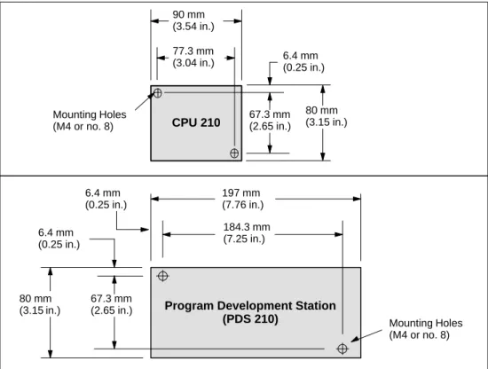
The CPU 210 and the PDS 210 include mounting holes to facilitate installation on panels. Figure 1-6 provides the mounting dimensions.
6.4 mm (0.25 in.) 77.3 mm (3.04 in.) CPU 210 Mounting Holes (M4 or no. 8) 80 mm (3.15 in.) 67.3 mm (2.65 in.) 90 mm (3.54 in.) 6.4 mm (0.25 in.) 184.3 mm (7.25 in.)
Program Development Station
(PDS 210) Mounting Holes (M4 or no. 8) 197 mm (7.76 in.) 6.4 mm (0.25 in.) 80 mm (3.15 in.) 67.3 mm (2.65 in.)
1.3
Installing a CPU 210
Warning
Failure to disable all power to the CPU 210 and related equipment during installation or removal procedures may result in death or serious personal injury, and/or damage to equipment.
Disable all power to the CPU 210 and related equipment before installation or removal. Always follow appropriate safety precautions and ensure that power to the CPU 210 is disabled before installation.
Mounting a CPU 210 on a Panel
To install a CPU 210 on a panel, follow these steps:
1. Locate, drill, and tap the mounting holes for DIN M4 or American Standard number 8 screws. Refer to Section 1.2 for mounting dimensions and other considerations. 2. Secure the CPU 210 onto the panel, using DIN M4 or American Standard number 8
screws.
Installing a CPU 210 on a DIN Rail
To install a CPU 210 on a DIN rail (as shown in Figure 1-7), follow these steps: 1. Secure the DIN rail every 75 mm (approximately 3 inches) to the mounting panel. 2. Snap open the DIN clip (located on the bottom of the CPU 210) and hook the back of the
module onto the DIN rail.
3. Snap the DIN clip closed, carefully checking to ensure that the DIN clip fastened the module securely onto the rail.
Note
Modules in an environment with high vibration potential or modules that have been installed in a vertical position may require DIN Rail Stops.
CPU 210
DIN Clip
Fasten DIN rail every 75 mm (approximately 3 inches)
Figure 1-7 Installing a CPU 210 on a DIN Rail
Installing a CPU 210 in a Panel Box
To install a CPU 210 in a panel box, follow these steps:
1. Open one of the I/O access covers on the CPU 210. As shown in Figure 1-8, remove the access cover by gently pressing against the access cover until the hinges spring free. Repeat this procedure for the other access cover.
Open the access cover. Gently press against the access cover until the access cover snaps off. Access covers
CPU 210 (Side View)
CPU 210
(Side View) (Side View)CPU 210 CPU 210 (Side View)
Figure 1-8 Removing the Access Covers from the CPU 210
2. Snap open the DIN clip (located on the bottom of the module).
3. Open the panel box and hook the back of the module onto the DIN rail. See Figure 1-9. 4. Snap the DIN clip closed, carefully checking to ensure that the DIN clip fastened the
module securely onto the rail.
CPU 210
DIN Clip DIN rail
1.4
Installing the Field Wiring
Warning
Failure to disable all power to the CPU 210 and related equipment during installation or removal procedures may result in death or serious personal injury, and/or damage to equipment.
Disable all power to the CPU 210 and related equipment before installing or removing field wiring.
Always follow appropriate safety precautions and ensure that power to the CPU 210 is disabled before installing field wiring.
General Guidelines
The following items are general guidelines for designing the installation and wiring of your S7-200 CPU 210:
S
Ensure that you follow all applicable electrical codes when wiring the CPU 210. Install and operate all equipment according to all applicable national and local standards. Contact your local authorities to determine which codes and standards apply to your specific case.S
Always use the proper wire size that will carry the required current. The CPU 210 accepts wire sizes from 1.50 to 0.50 mm2 (14 to 22 AWG).S
Ensure that you do not over-tighten the connector screws. The maximum torque is 0.56 N-m (5 inches-pounds).S
Always use the shortest wire possible (maximum 500 meters shielded, 300 meters unshielded). Wiring should be run in pairs, with a neutral or common wire paired with a hot or signal-carrying wire.S
Separate AC wiring and high-energy, rapidly switched DC wiring from low-energy signal wiring.S
Properly identify and route the wiring to the CPU 210, using strain relief for the wiring as required. For more information about identifying the terminals, see the data sheets in Appendix A.S
Install appropriate surge suppression devices for wiring that is subject to lightning surges.S
External power should not be applied to an output load in parallel with a DC output point.This may cause reverse current through the output, unless a diode or other barrier is provided in the installation.
Warning
Control devices can fail in an unsafe condition, resulting in unexpected operation of controlled equipment.
Such unexpected action could result in death or serious personal injury, and/or equipment damage.
Consider using an emergency stop function, electromechanical overrides, or other redundant safeguards that are independent of the programmable controller.
!
Grounding and Circuit Referencing Guidelines for Using Isolated Circuits
The following items are grounding and circuit guidelines for using isolated circuits:
S
You should identify the reference point (0 voltage reference) for each circuit in theinstallation, and the points at which circuits with possible different references can connect together. Such connections can result in unwanted current flows that can cause logic errors or damage circuits. A common cause of different reference potentials is grounds which are physically separated by long distances. When devices with widely separated grounds are connected with a sensor cable, unexpected currents can flow through the circuit created by the cable and the ground. Even over short distances, load currents of heavy machinery can cause differences in ground potential or directly induce unwanted currents by electromagnetic induction. Power supplies that are improperly referenced with respect to each other can cause damaging currents to flow between their associated circuits.
S
The CPU 210 includes isolation boundaries at certain points to help prevent unwanted current flows in your installation. When you plan your installation, you should consider where these isolation boundaries are, and where they are not provided. You should also consider the isolation boundaries in associated power supplies and other equipment, and where all associated power supplies have their reference points.S
You should choose your ground reference points and use the isolation boundaries provided to interrupt unneeded circuit loops that could allow unwanted currents to flow. Remember to consider temporary connections which may introduce a new circuit reference, such as the connection of a programming device to the CPU.S
When locating grounds, you must also consider safety grounding requirements and the proper operation of protective interrupting devices.The following descriptions are an introduction to general isolation characteristics of the CPU 210, but some features may be different on specific products. Consult the data sheet in Appendix A for your product for specifications of which circuits include isolation boundaries and the ratings of the boundaries. Isolation boundaries rated less than 1500 VAC are designed as functional isolation only and should not be depended on as safety boundaries.
S
CPU logic reference is the same as DC Sensor Supply M.S
CPU logic reference is the same as the input power supply M on a CPU with DC power supply.S
CPU logic is isolated from ground to 100 VDC.S
DC digital inputs and outputs are isolated from CPU logic to 500 VAC.S
Relay outputs and AC inputs are isolated from CPU logic to 1500 VAC.S
Relay output groups are isolated from each other by 1500 VAC.S
AC power supply Line and Neutral are isolated from ground, the CPU logic, and all I/O to 1500 VAC.Using the Optional Field Wiring Connector
The optional field wiring fan-out connector (Figure 1-10) allows for field wiring connections to remain fixed when you remove and re-install the CPU 210. Refer to Appendix F for the order number. Field Wiring Fan-out Connector M L+ 0.0 0.1 0.2 0.3 DC OUTPUTS ↓ M L+ 24V DC
Figure 1-10 Optional Field Wiring Connector
Guidelines for AC Installation
The following items are general wiring guidelines for AC installations. Refer to Figure 1-11.
S
Provide a single disconnect switch (A) that removes power from the CPU, all inputcircuits, and all output (load) circuits.
S
Provide overcurrent devices (B) to protect the CPU power supply, the output points, and the input points. You can also fuse each output point individually for greater protection. External overcurrent protection for input points is not required when you use the 24 VDC sensor supply (C) from the CPU 210. This sensor supply is short-circuit protected.S
Connect all CPU 210 ground terminals to the closest available earth ground (D) toprovide the highest level of noise immunity. It is recommended that all ground terminals be connected to a single electrical point. Use 14 AWG or 1.5 mm2 wire for this
connection.
If required, you can use a DC Sensor Supply from the CPU 210 to supply power for the inputs (E). Refer to the guidelines for DC installation, especially in regard to connecting and external power supply in parallel with the power supply of the CPU 210.
Guidelines for DC Installation
The following items are general wiring guidelines for isolated DC installations. Refer to Figure 1-11.
S
Provide a single disconnect switch (1) that removes power from the CPU, all input circuits, and all output (load) circuits.S
Provide overcurrent devices to protect the CPU power supply (2), the output points (3), and the input points (4). You can also fuse each output point individually for greater protection. External overcurrent protection for input points is not required when you use the 24 VDC sensor supply from the CPU 210. This sensor supply is internally current limited.S
Ensure that the DC power supply has sufficient surge capacity to maintain voltage during sudden load changes. External capacitance (5) may be required.S
Install or equip ungrounded DC power supplies with a resistor and a capacitor in parallel (6) from the power source common to protective earth ground. The resistor provides a leakage path to prevent static charge accumulations, and the capacitor provides a drain for high frequency noise. Typical values are 1M Ω and 4700 pf. You can also create a grounded DC system by connecting the DC power supply to ground (7).S
Connect all CPU 210 ground terminals to the closest available earth ground (8) to provide the highest level of noise immunity. It is recommended that all ground terminals be connected to a single electrical point. Use 14 AWG or 1.5 mm2 wire for thisconnection.
S
Always supply 24 VDC circuits from a source that provides safe electrical separation from 120/230 VAC power and similar hazards. Refer to the following documents for standard definitions of “safe separation”: PELV (protected extra low voltage) according to EN60204-1, and Class 2 or Limited Voltage/Current Circuit according to UL 508.Warning
Connecting an external 24 VDC power supply in parallel with the DC sensor supply of the CPU 210 can result in a conflict between the two supplies as each seeks to establish its own preferred output voltage level. The result of this conflict can be shortened lifetime or immediate failure of one or both power supplies, with consequent unpredictable operation of the PLC system. Unpredictable operation could result in death or serious injury to personnel, and/or damage to equipment and property.
The CPU 210 DC Sensor Supply and any external power supply should provide power to different points, with at most one connection between the two supplies.
L1 N PE (1) DO DI P/S CPU 210 DC/DC/DC (5) (6) (2) (3) (4) (7) L+ M 24 VDC AC DC (8) Floating (6) or Grounded (7) L1 N PE (A) (D) DO DI P/S M L+ (C) CPU 210 AC/DC/Rly (E) Fuse (B) (B)
120/230 VAC Using a Single Overcurrent Switch to Protect the CPU and Load Wiring
Isolated DC System Installation
Figure 1-11 Wiring Guidelines for AC and DC Installation
1.5
Using Suppression Circuits
Install or equip inductive loads with suppression circuits that limit voltage rise on loss of power. Use the following guidelines to design adequate suppression. The effectiveness of a given design is dependent on the application, and you must verify it for a particular use. Be sure all components are rated for use in the application.
Protecting DC Transistors
The DC transistor outputs of the CPU 210 contain zener diodes that are adequate for many installations. Use external suppression diodes for either large or frequently switched inductive loads to prevent overpowering the internal diodes. Figure 1-12 shows typical applications for DC transistor outputs.
+VDC (1) IN4001 diode or equivalent (1) Inductor (1) IN4001 diode or equivalent (2) 8.2 V zener, 5 W +VDC (1) (2) Inductor Zener Diode Suppression Diode Suppression
Figure 1-12 Diode Suppression and Zener Diode Suppression
Protecting Relays Controlling DC Power
Resistor/capacitor networks, as shown in Figure 1-13, can be used for low voltage (30 V) DC relay applications. Connect the network across the load. You can also use diode
suppression, as shown in Figure 1-12, for DC relay applications. A threshold voltage of up to 36 V is allowed if you use a reverse zener diode.
+VDC where minimum R = 12Ω R C IL Inductor RVDC IL where K is 0.5 to 1 µ F/A CILK
This manual describes Version 2.0 of STEP 7-Micro/WIN. Previous versions of the software may operate differently.
STEP 7-Micro/WIN is a Windows-based software application used for programming the S7-200 Micro PLC (programmable logic controller). The STEP 7-Micro/WIN programming software package provides a set of tools required to program the S7-210 in either statement list (STL) or ladder logic (LAD) programming language.
In order to use STEP 7-Micro/WIN, you must have the following equipment:
S
Recommended: a personal computer (PC) with an 80486 or greater processor and 8 Mbyte of RAM or a Siemens programming device (such as a PG 740); minimum computer requirement: 80386 with 8 Mbyte of RAMS
A PC/PPI cable connected to your communications port (COM)S
A program development station (PDS 210)S
VGA monitor, or any monitor supported by Microsoft WindowsS
At least 35 Mbyte of free hard disk space (recommended)S
Microsoft Windows 3.1, Windows for Workgroups 3.11, Windows 95, or Windows NT 3.51 or greaterS
Optional but recommended: any mouse supported by Microsoft WindowsSTEP 7-Micro/WIN provides extensive online help. Use the Help menu command or press F1 to obtain the most current information.
Chapter Overview
Section Description Page
2.1 Installing the STEP 7-Micro/WIN Version 2.0 Software 2-2
2.2 Establishing Communication with the PDS 210 2-3
2.3 Configuring the Preferences for STEP 7-Micro/WIN 2-5
2.4 Creating and Saving a Project 2-6
2.5 Creating a Program 2-7
2.6 Downloading a Program 2-10
2.7 Using Symbolic Addressing 2-13
2.8 Using the Status Chart 2-15
2.9 Debugging and Monitoring Your Program 2-16
2.1
Installing the STEP 7-Micro/WIN Version 2.0 Software
Pre-installation Instructions
Before running the setup procedure, do the following:
S
If a previous version of STEP 7-Micro/WIN is installed, back up all application programs to diskette.S
Make sure all applications are closed, including the Microsoft Office toolbar. Installation may require that you restart your computer.Installation Instructions for Windows 3.1
If you have Windows 3.1 (Windows for Workgroups 3.11 or Windows NT) on your machine, use the following procedure to install the STEP 7-Micro/WIN software:
1. Start by inserting Disk 1 in the disk drive of your computer (usually designated drive A: or drive B:).
2. From the Program Manager, select the menu command File " Run...
3. In the Run dialog box, type a:\setup and click on the “OK” button. This starts the setup procedure.
4. Follow the online setup procedure to complete the installation.
Installation Instructions for Windows 95
If you have Windows 95 on your machine, you can use the following procedure to install the STEP 7-Micro/WIN software:
1. Start by inserting Disk 1 in the disk drive of your computer (usually designated drive A: or drive B:).
2. Click once on the Start button to open the Windows 95 menu. 3. Click on the Run... menu item.
4. In the Run dialog box, type a:\setup and click on the “OK” button. This starts the setup procedure.
5. Follow the online setup procedure to complete the installation.
Troubleshooting the Installation
The following situations can cause the installation to fail:
S
Not enough memory: you need to have at least 35 Mbyte of free space on your hard disk.S
Bad diskette: verify that the diskette is bad, then call your salesman or distributor.S
Operator error: start over and read the instructions carefully.S
Failure to close any open applications, including the Microsoft Office toolbar.Note
Review the READMEx.TXT file included on your diskettes for the most recent information about STEP 7-Micro/WIN. (In the x position, the letter A = German, B = English,
2.2
Establishing Communication with the PDS 210
Connecting Your Computer to the PDS 210 for PPI Communications
Figure 2-1 shows a typical configuration for connecting your personal computer to your PDS 210 with the PC/PPI cable. To establish proper communications between the components, follow these steps:
1. Set the dipswitches on the PC/PPI cable for the baud rate of 9600 baud.
2. Connect the RS-232 end of the PC/PPI cable labeled PC to the communications port of your computer, either COM1 or COM2, and tighten the connecting screws.
3. Connect the other end (RS-485) of the PC/PPI cable to the communications port of the PDS 210, and tighten the connecting screws.
RS-232
Program development station (PDS 210) PC/PPI cable Computer Dipswitch Settings: 0 1 0 0 = 9600 baud RS-485
Setting Up the Communications Parameters
Figure 2-2 shows the Setup Communications dialog box. The first two port options are for PC communication ports. The address for the PDS 210 is 2 and cannot be changed. To set up the communication parameters, follow these steps:
1. Select the menu command Setup " Communications...
2. Verify that the information in the dialog box is correct for your configuration. Remember that the CPU address for the PDS 210 is always 2, and that the baud rate is always 9600.
3. Confirm your selections by clicking the “OK” button.
✂
Project Edit View CPU Debug Tools Setup Window HelpSetup
Preferences... Communications... Communications Cancel Find OK 2 0 CPU Address: Micro/WIN Address: COM1 COM2 Port MPI Card 9,600 Baud Rate: 31
Highest Master Address:
10
IRQ Number For MPI Card:: 39
Target Token Rotation Time::
2.3
Configuring the Preferences for STEP 7-Micro/WIN
Before creating a new project, specify the preferences for your programming environment. To select your preferences, follow these steps:
1. Select the menu command Setup " Preferences... as shown in Figure 2-3. 2. Select your programming preferences in the dialog box that appears. 3. Confirm your choices by clicking the “OK” button.
✂ Preferences Cancel OK English STL Editor Ladder Editor Default Editor International SIMATIC Mnemonic Set Program Editor Initial Window States
Language
Data Block Editor Maximize All
Symbol Table Status Chart Project Edit View CPU Debug Tools Setup Window HelpSetup
Preferences...
Communications...
Normalized
Minimized Minimized Minimized
Options for an Uploaded Data Block
Data Format
Retain Format and Comments Data Size
Hexadecimal Byte
2.4
Creating and Saving a Project
Before you create a program, you must create or open a project. When you create a new project, STEP 7-Micro/WIN opens the following editors:
S
Ladder Editor or Statement List Editor (depending on your selected preference)S
Data Block Editor (not applicable for the PDS 210)S
Status ChartS
Symbol TableCreating a New Project
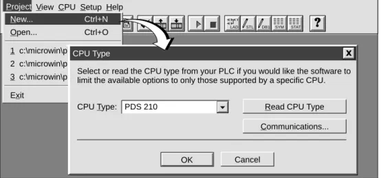
The Project menu command allows you to create a new project, as shown in Figure 2-4. Select the menu command Project " New.... The CPU Type dialog box is displayed. If you select the CPU type from the drop-down list box, the software displays only those options which are available for your CPU. If you select “None,” no CPU-specific restrictions are placed on your program. When you download the program, the CPU notifies you if you have used options that are not available. For example, if your program uses an instruction that is not supported by your CPU, the program is rejected.
Note
STEP 7-Micro/WIN does not range-check parameters. For example, you can enter MW999 as a parameter to a ladder instruction even though it is an invalid parameter. This error would be identified when you attempt to download the program.
✂
Project View CPU Setup Help
Project
LAD STL DB1 SYM STAT New... Ctrl+N Open... Ctrl+O 1 c:\microwin\project1.prj 2 c:\microwin\project2.prj 3 c:\microwin\project3.prj Exit CPU Type Cancel OK
Select or read the CPU type from your PLC if you would like the software to limit the available options to only those supported by a specific CPU.
Read CPU Type Communications... PDS 210
CPU Type:
Figure 2-4 Creating a New Project
Saving a Project
You can save a copy of the active project to a different name or location by selecting the menu command Project " Save As... You can save all of the components of your project by selecting the menu command Project " Save All or by clicking the Save button:
2.5
Creating a Program
STEP 7-Micro/WIN allows you to create the user program (OB1) with either the Ladder Editor or the Statement List Editor.
Entering Your Program in Ladder
The Ladder Editor window allows you to write a program using graphical symbols. See Figure 2-5. The toolbar includes some of the more common ladder elements used to enter your program. The first (left) drop-down list box contains instruction categories. You can access these categories by clicking or pressing F2. After a category is selected, the second drop-down list contains the instructions specific to that category. To display a list of all instructions in alphabetic order, press F9 or select the All Instructions category. Each network allows two types of comments:
S
Single-line network title comments are always visible in the ladder display. You can access the network editor by double-clicking anywhere in the network title region.S
Multi-line network comments are only visible through a dialog box, but can be printed (ifthat option has been selected through the Page Setup dialog). You can access the network comment editor by double-clicking anywhere in the network title region. To start entering your program, follow these steps:
1. To enter a program title, select the menu command Edit " Program Title. 2. To enter ladder elements, select the type of element you want by clicking the
corresponding icon button or selecting from the instruction list. 3. Type the address or parameter in each text field and press ENTER.
To change or replace one of the elements, move the cursor to that element and select the new element. You can also cut, copy, or paste elements at the cursor location.
Ladder Editor - project1.ob1
Contacts Normally Open
NETWORK TITLE (single line)
Press ENTER or double-click to place element. I0.0 Network 1 F4 F5 F6 F7 F8 F10 F3 F2
Double click here to access the network title and comment editor.
Entering Your Program in Statement List
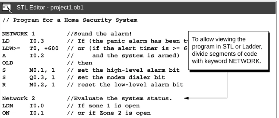
The Statement List (STL) Editor is a free-form text editor which allows a certain degree of flexibility in the way you choose to enter program instructions. Figure 2-6 shows an example of a statement list program.
You can cut, copy, and paste in the STL Editor. STEP 7-Micro/WIN also includes search-and-replace functions.
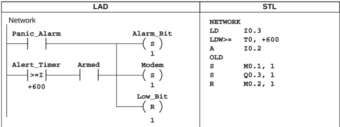
// Program for a Home Security System NETWORK 1 //Sound the alarm!
LD I0.3 // If (the panic alarm has been turned on) LDW>= T0, +600 // or (if the alert timer is >= 60 seconds A I0.2 // and the system is armed)
OLD // then
S M0.1, 1 // set the high-level alarm bit S Q0.3, 1 // set the modem dialer bit R M0.2, 1 // reset the low-level alarm bit Network 2 //Evaluate the system status. LDN I0.0 // If zone 1 is open
ON I0.1 // or if Zone 2 is open
STL Editor - project1.ob1 STL
To allow viewing the program in STL or Ladder, divide segments of code with keyword NETWORK.
Figure 2-6 STL Editor Window with Sample Program
To enter an STL program, follow these guidelines:
S
Start each comment with a double slash (//). Each additional comment line must also begin with a double slash.S
End each line with a carriage return.S
Separate each instruction from its address or parameter with a space or tab.S
Do not use a space between the operand type and the address (for example, enter I0.0, not I 0.0).S
Separate each operand within an instruction with a comma, space, or tab.S
Use quotation marks when entering symbol names. For example, if your symbol table contains the symbol name Start1 for the address I0.0, enter the instruction as follows:LD “Start1”
To be able to view an STL program in ladder, you must divide segments of code into separate networks by entering the keyword NETWORK. (Network numbers are generated automatically after you compile or upload the program.)
Compiling the Program
After completing a network or series of networks, you can check the syntax of your code by selecting the menu command CPU " Compile or by clicking the Compile button:
Viewing a Program in Ladder or Statement List
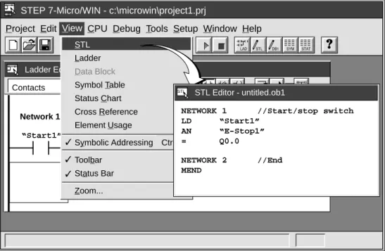
You can view a program in either ladder or STL by selecting the menu command View " STL or View " Ladder, as shown in Figure 2-7.
When you change the view from STL to ladder and back again to STL, you may notice changes in the presentation of the STL program, such as:
S
Instructions and addresses are changed from lower case to upper case.S
Spaces between instructions and addresses are replaced with tabs.You can accomplish the same formatting of the STL instructions by selecting the menu command CPU " Compile while the STL Editor is active.
Note
Certain combinations of statement list instructions cannot successfully be converted to ladder view. In that case, the message “Illegal Network” marks the section of code that cannot be represented in ladder. You can view the STL instructions for the “illegal” network by clicking on the network title. Use the STL Editor to modify an illegal network so that it can be viewed in ladder.
✂
Project Edit View CPU Debug Tools Setup Window Help STEP 7-Micro/WIN - c:\microwin\project1.prj
View
Ladder Editor - untitled.ob1
Contacts F2 Normally Open Start/stop switch “Start1” “E-Stop1” Q0.0 Network 1 ✓ ✓ ✓ STL Ladder Data Block Symbol Table Status Chart Cross Reference Element Usage
Symbolic Addressing Ctrl+Y Toolbar Status Bar Zoom... F4 F5 F6 F7 F8 F3 F10 STL Editor - untitled.ob1
NETWORK 1 //Start/stop switch LD “Start1” AN “E-Stop1” = Q0.0 NETWORK 2 //End MEND STL
2.6
Downloading A Program
After developing and testing your program on the PDS 210, you must transfer the program to the CPU 210 using the memory cartridge. In the same manner as you could use a diskette to transfer files from one computer to another, you use a memory cartridge to transfer your program from the PDS 210 to the CPU 210.
Downloading the Program to the PDS 210
After completing your program, you can download the project to the PDS 210. To download your program, select the menu command Project " Download... or click the Download button in the main window.
The Download dialog box that appears allows you to specify the project components you want to download, as shown in Figure 2-8. Select only “Program Code Block” for the PDS 210: the data block and the CPU configuration are not used by the CPU 210. Click on the “OK” button to confirm your choices and to execute the download operation.
✂
Project Edit View CPU Debug Tools Setup Window Help STEP 7-Micro/WIN - c:\microwin\project1.prj
Download Cancel OK All Data Block CPU Configuration Project New... Ctrl+N Open... Ctrl+O Close Save All Ctrl+S Save As... Import Export Upload... Ctrl+U Download... Ctrl+D Page Setup... Print Preview... Print... Ctrl+P Print Setup... Exit
Program Code Block
Copying Your Program to the Memory Cartridge
You can copy your program to the memory cartridge only when the PDS 210 is powered up and the memory cartridge is installed. (You can install or remove the memory cartridge while the PDS 210 is powered up.)
Caution
Electrostatic discharge can damage the memory cartridge or the receptacle on the PDS 210 or CPU 210.
You should make contact with a grounded conductive pad and/or wear a grounded wrist strap when you handle the cartridge. You should store the cartridge in a conductive container.
To install the memory cartridge, remove the protective tape from the memory cartridge receptacle and insert the memory cartridge into the receptacle located under an access cover of the PDS 210. (The memory cartridge is keyed for proper installation.) After the memory cartridge is installed, use the following procedure to copy the program: 1. If the program has not already been downloaded to the PDS 210, use the menu
command Project " Download... to download the program. (See Figure 2-8.)
2. Use the menu command CPU " Program Memory Cartridge to copy the program to the memory cartridge. See Figure 2-9.
3. Remove the memory cartridge from the PDS 210.
✂
Project Edit View CPU Debug Tools Setup Window Help STEP 7-Micro/WIN - c:\microwin\project1.prj
CPU
Ladder Editor - untitled.ob1
Contacts F2 Normally Open Start/stop switch “Zone_1” “Zone_2” Q0.0 Network 1 ✓ Run Stop Compile Clear Information Configure
Program Memory Cartridge
Time of Day Clock Compare Project to CPU Type
Figure 2-9 Copying the Program to the Memory Cartridge
Transferring the Program to the CPU 210
To transfer the program from the memory cartridge to the CPU 210, follow these steps: 1. Turn off the power to the CPU 210.
2. Insert the memory cartridge in the CPU 210. (The memory cartridge is keyed for proper installation.)
3. Turn on the power to the CPU 210.
4. After the RUN LED turns on, remove the memory cartridge from the CPU 210.
As shown in Figure 2-10, the CPU 210 performs the following tasks after you turn the power on when a memory cartridge is installed in the CPU 210:
S
The M, T, and Q areas of memory are cleared.S
The current values for the counters (which are stored in the permanent memory) are cleared. (The current values for the counters are erased only when the memory cartridge is installed in the CPU 210. If a memory cartridge is not installed, the current values are retained.)S
The user program is copied from the memory cartridge to the permanent EEPROM memory.Always remove the memory cartridge from the CPU 210 after the program has been installed.
Note
Turning the power on with a blank memory cartridge in the CPU 210 causes an error and lights the error LED. Any program stored in the permanent EEPROM is not affected or overwritten. To correct the error condition, remove the memory cartridge and cycle the power again.
When a valid program is installed, the CPU 210 automatically goes to RUN mode when power is applied.
As your program runs, the CPU 210 updates the values stored in the RAM memory (the values stored in M memory, the current values for the four counters, and the current values for the four timers).
When you turn the power off, the CPU 210 saves the current values of the four counters to the permanent EEPROM memory. The other values stored in RAM (such as M memory, current values for the timers, and the copy of the user program) are cleared.
Unless a memory cartridge is installed in the CPU 210, the current values for the counters are retentive. The current values for the counters are automatically restored to the RAM memory when you turn power on for the CPU 210 (with no memory cartridge installed).
User Program
EEPROM Memory (Permanent)
RAM Memory
M memory
Current values of the counters Current values
of the counters Counter values
Current values of the timers Memory
Cartridge
When the memory cartridge is installed in the CPU 210, turning on the power copies the user program to the permanent memory
2.7
Using Symbolic Addressing
The Symbol Table allows you to give symbolic names to inputs, outputs, and internal memory locations. See Figure 2-11. You can use the symbols you have assigned to these addresses in the Ladder Editor, STL Editor, and Status Chart of STEP 7-Micro/WIN.
Guidelines for Entering Symbolic Addresses
The first column of the Symbol Table is used to select a row. The other columns are for the symbol name, address, and comment. For each row, you assign a symbolic name to the absolute address of a discrete input, output, memory location, special memory bit, or other element. A comment for each assigned symbol is optional. Follow these guidelines when creating a Symbol Table:
S
You can enter symbol names and absolute addresses in any order.S
You can use up to 23 characters in the Symbol Name field; however, depending on the font size of your Windows environment, you may not see the full name displayed in the Ladder Editor.S
You can define up to 500 symbols.S
The Symbol Table is case-sensitive: for example, “Low_Alert” is considered a different symbol from “low_alert”.S
All leading and trailing spaces will be removed from the symbol name. All adjacent internal spaces will be converted to a single underscore. For example, if you type “Zone 1” and press ENTER, the symbol name appears as: “Zone_1”.S
Duplicate symbol names and/or addresses will be marked by blue italics, will not be compiled, and cannot be used in the program. Overlapping addresses are not flagged as duplicates; for example, MW0 and MW1 overlap in memory but are not flagged as duplicates.Starting the Symbol Table Editor
The Symbol Table editor appears by default as a minimized window icon at the bottom of the main window. To access the Symbol Table, double-click the icon, or click the Restore or Maximize button on the icon (in Windows 95).
Symbol Table - untitled.sym
Zone_1 Zone_2 Armed Panic_Alarm LED I0.0 I0.1 I0.2 I0.3 Q0.0 Alarm Low_Alert Q0.1 Q0.2 LED_Bit M0.0 LED_Bit M0.1 Zone 1 (switches A to F)
Enables the security system Turns on the siren
Zone 2 (switches H to M)
Duplicate symbols are displayed in italics.
Symbol Name Address Comment
To clear a cell, press delete key or spacebar when cell is selected.
Editing Functions within the Symbol Table
The Symbol Table provides the following editing functions:
S
Edit " Cut / Copy / Paste within a cell or from one cell to another.S
Edit " Cut / Copy / Paste one or several adjacent rows.S
Edit " Insert Row(s) above the row containing the cursor. You can also use the INSERT or INS key for this function.S
Edit " Delete Row(s) for one or several highlighted adjacent rows. You can also use the DELETE or DEL key for this function.S
To edit any cell containing data, use the arrow keys or mouse to select the cell you want to edit. If you begin typing, the field clears and the new characters are entered. If you double-click the mouse or press F2, the field becomes highlighted, and you can use the arrow keys to move the editing cursor to the place you want to edit.S
Clicking the right mouse button displays a menu of editing functions which are available with the Symbol Table editor.Sorting Table Entries
After entering symbol names and their associated absolute addresses, you can sort the Symbol Table alphabetically by symbol names or numerically by addresses in the following ways:
S
Select the menu command View " Sort Symbol Name to sort the symbol names in alphabetical order.S
Select the menu command View " Sort Symbol Address to sort the absolute addresses numerically in the following order for memory types: I, Q, M, C, T, and SM.Displaying the Symbolic Addresses
After you create the Symbol Table for your program, you can use the menu command View "
Symbolic Addressing to enable or disable the use of symbolic addressing with the Program
Editor (ladder or STL) and the Status Chart. See Figure 2-12.
✂
Project Edit View CPU Debug Tools Setup Window Help STEP 7-Micro/WIN - c:\microwin\project1.prj
View
Ladder Editor - untitled.ob1
Contacts F2 Normally Open Start/stop switch “Start1” “E-Stop1” Q0.0 Network 1 ✓ ✓ ✓ STL Ladder Data Block Symbol Table Status Chart Cross Reference Element Usage Symbolic Addressing Toolbar Status Bar Zoom...
2.8
Using the Status Chart
The Status Chart editor appears by default as a minimized window icon at the bottom of the main window. To access the Status Chart, double-click the icon, or click the Restore or Maximize button on the icon (in Windows 95).
You can use the Status Chart to read or write variables in your program. You cannot force values in the PDS 210.
Reading and Writing Variables with the Status Chart
Figure 2-13 shows an example of a Status Chart. To read or write variables using the Status Chart, follow these steps:
1. In the first cell in the Address column, enter the address or the symbol name of an element from your program that you want to read or write, and press ENTER. Repeat this step for all additional elements you want in the chart.
2. If the element is a bit (I, Q, or M, for example), the format is set as bit in the Format column. If the element is a word, select the cell in the Format column and double-click or press the SPACEBAR to cycle through the valid formats.
3. To view the current PLC value of the elements in your chart, click the Single Read button or the Continuous Read button on the Status Chart.
You can click the Stop Read button to stop the updating of status.
4. To change a value, enter the new value in the Change Value to column and click the Write button to write the value to the PDS 210.
Status Chart Address Format I0.0 Bit 2#0 I0.1 Bit 2#0 Q0.1 Bit 2#1 Change Value to Q0.2 Bit 2#0 T0 Integer +84 MW0 Integer 4400 1 Current PLC Value To change a value, enter new value here and click the Write button.
Press the spacebar or double-click in the cell to select valid format.
Figure 2-13 Example of a Status Chart
Editing Addresses
To edit an address cell, use the arrow keys or mouse to select the cell you want to edit.
S
If you begin typing, the field clears and the new characters are entered.S
If you double-click the mouse or press F2, the field becomes highlighted and you can use the arrow keys to move the editing cursor to the place you want to edit.S
Clicking the right mouse button displays a menu of editing functions which are available with the Status Chart editor.2.9
Debugging and Monitoring Your Program
Using Single/Multiple Scans to Monitor Your Program
You can specify that the PDS 210 execute your program for a limited number of scans (from 1 scan to 65,535 scans). By selecting the number of scans for the PDS 210 to run, you can monitor the program as it changes the process variables. Use the menu command
Debug " Execute Scans... to specify the number of scans to be executed. Figure 2-14 shows the dialog box for entering the number of scans for the CPU to execute.
Execute Scan
OK Cancel 1
Execute program scan(s)
Figure 2-14 Executing Your Program for a Specific Number of Scans
Displaying the Status of the Program in Ladder Logic
As shown in Figure 2-15, the program editor of STEP 7-Micro/WIN allows you to monitor the status of the online program. (The program must be displaying ladder logic.) This allows you to monitor the status of the instructions in the program as they are executed by the CPU.
✂
Project Edit View CPU Debug Tools Setup Window Help STEP 7-Micro/WIN - c:\microwin\house.prj
Contacts F2 Normally Open F3 F4 F5 F6 F7 F8 F10
Debug Execute Scans... Ladder Status On T0 >=I +600 I0.3 I0.2 M0.1 S 1 Q0.3 S 1 M0.2 R
Sound the alarm!
Network 1
2.10 Error Handling for the PDS 210
The PDS 210 classifies errors as either fatal errors or non-fatal errors. You can use STEP 7-Micro/WIN to view the error codes that were generated by the error. Figure 2-16 shows the dialog box that displays the error code and the description of the error. Refer to Appendix C for a complete listing of the error codes.
CPU Information
General Information
Close Error Status Module Configuration
Module Errors Module 0: Module 1: Module 2: Module 3: Not present Not present Not present Not present Module 4: Module 5: Module 6: Not present Not present Not present CPU Errors Fatal: NON-Fatal: 0 83
No fatal errors present. Missing main end statement.
Use the description and the code for troubleshooting the possible cause of the error.
DP Status
NON-Fatal: 11
Figure 2-16 CPU Information Dialog: Error Status Tab
Responding to Fatal Errors
Fatal errors cause the PDS 210 to stop the execution of your program. Depending upon the severity of the fatal error, it can render the PDS 210 incapable of performing any or all functions. The objective for handling fatal errors is to bring the PDS 210 to a safe state from which the PDS 210 can respond to interrogations about the existing error conditions. When a fatal error is detected by the PDS 210, the PDS 210 changes to the STOP mode, turns on the System Fault LED and the STOP LED, and turns off the outputs. The PDS 210 remains in this condition until the fatal error condition is corrected.
Once you have made the changes to correct the fatal error condition, you must restart the PDS 210. You can restart the PDS 210 by cycling power. Restarting the PDS 210 clears the fatal error condition and performs power-up diagnostic testing to verify that the fatal error has been corrected. If another fatal error condition is found, the PDS 210 again sets the fault LED indicating that an error still exists. Otherwise, the PDS 210 begins normal operation.
There are several possible error conditions that can render the PDS 210 incapable of communication. In these cases, you cannot view the error code from the PDS 210. These errors indicate hardware failures that require the PDS 210 module to be repaired; these conditions cannot be fixed by changes to the program or clearing the PDS 210 memory.
Responding to Non-Fatal Errors
Non-fatal errors can degrade some aspect of the PDS 210 performance, but they do not render the PDS 210 incapable of executing your program or from updating the I/O. As shown in Figure 2-16, you can use STEP 7-Micro/WIN to view the error codes that were generated by the non-fatal error. For the PDS 210, there are two basic categories of non-fatal errors:
S
Run-time errors. All non-fatal errors detected in RUN mode are reflected in specialmemory (SM) bits. Your program can monitor and evaluate these bits. Refer to
Appendix B for more information about the SM bits used for reporting non-fatal run-time errors.
S
Program-compile errors. The PDS 210 compiles the program as it downloads. If the PDS 210 detects that the program violates a compilation rule, the download is aborted and an error code is generated. (A program that was already downloaded to the PDS 210 would still exist in the EEPROM and would not be lost.) After you correct your program, you can download it again.You can enter the program for the sample application on a computer running
STEP 7-Micro/WIN. To download the program, you must have the equipment shown in Figure 3-1. The size of the sample program is 155 bytes.
Input Simulator for the PDS 210
Program Development Station (PDS 210)
PC/PPI Communications Cable Computer
STEP 7-Micro/WIN
Figure 3-1 Requirements to Run the Sample Program
Chapter Overview
Section Description Page
3.1 Defining the Requirements for the Application Example 3-2
3.2 Designing the Control Logic 3-4
3.3 Putting the Control Logic into a Program 3-9
3.4 Creating a Project with STEP 7-Micro/WIN 3-13
3.5 Creating a Symbol Table 3-14
3.6 Creating the Program 3-15
3.7 Creating a Status Chart 3-22
3.8 Downloading and Monitoring the Sample Program 3-23
3.9 Modifying the Sample Program 3-25
3.1
Defining the Requirements for the Application Example
Defining the Inputs and Outputs for the Application
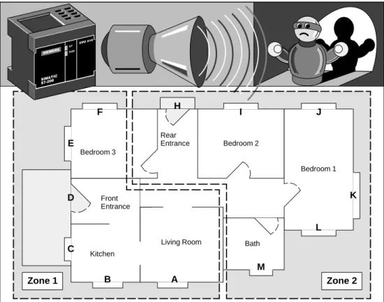
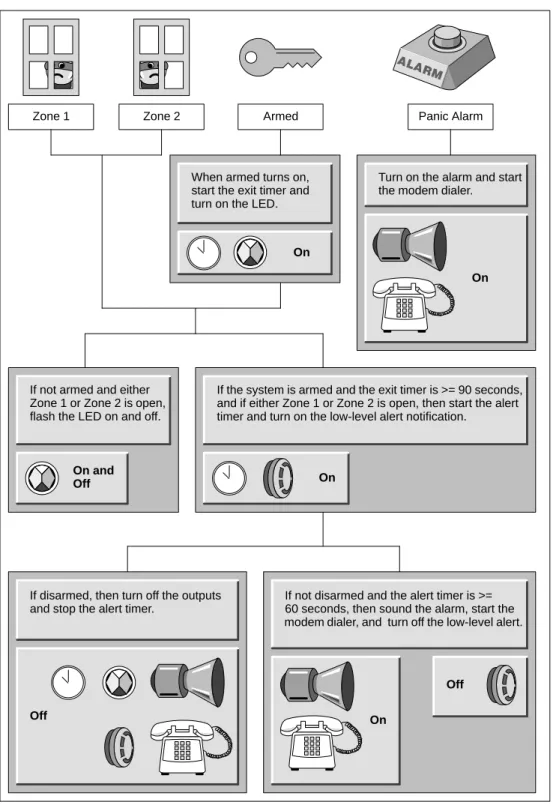
This chapter describes a sample program for a home security system. As shown in
Figure 3-2, the program monitors two zones. Any breach of security results in an alarm being sounded. The sample program uses the following inputs:
S
Input 1 (I0.0) monitors zone 1 (entrance, living room, kitchen, and bedroom 3).S
Input 2 (I0.1) monitors zone 2 (bedroom 1, bedroom 2, bathroom, and rear entrance).S
Input 3 (I0.2) provides the arm/disarm switch for the security system.S
Input 4 (I0.3) provides a “panic button” to immediately turn on the alarm siren. In addition to the inputs, the program uses the following outputs.S
Output 1 (Q0.0) controls the LED on the security system.S
Output 2 (Q0.1) turns on the siren to sound an alarm.S
Output 3 (Q0.2) turns on a low-level notification alert to signify that the alarm will be turned on in a predetermined number of seconds.S
Output 4 (Q0.3) turns on an external interface relay (perhaps to an automatic dialing machine).Figure 3-3 shows a wiring diagram for the home security application.
Creating Symbolic Names for the Elements of the Program
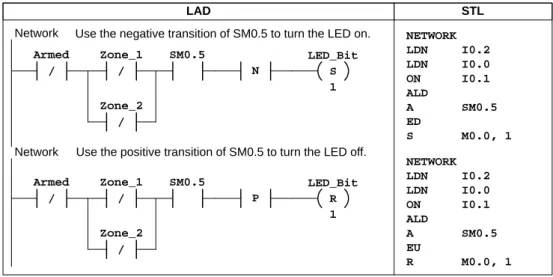
Symbolic names help to document or define the specific memory locations or I/O used by your program. Table 3-1 lists the symbolic names used by the program for the sample application. The sample program also uses SM0.5 to generate an on/off (blinking) pattern for the LED.
Table 3-1 Symbolic Names for the Application Example
Element Address Symbolic Name Description
I
I0.0 Zone_1 Normally Closed input for Zone 1 Inputs
I0.1 Zone_2 Normally Closed input for Zone 2 Inputs
I0.2 Armed Armed = closed, and disarmed = open I0.3 Panic_Alarm Normally Open input for panic alarm
O
Q0.0 LED System LED (on if armed, or flashing if disarmed and zone 1 or zone 2 open)
Outputsp Q0.1 Alarm High-level alarm (siren) Q0.2 Low_Alert Low-level alert to disarm system Q0.3 Modem Relay to start the modem dialer unit Internal
M0.0 LED_Bit Stores the status for the LED Internal
Memory M0.1 Alarm_Bit Stores the status for the alarm Memory
M0.2 Low_Bit Stores the status for the low-level alert Timers
T0 Alert_Timer Provides a delay before the alarm turns on Timers