RESEARCH PAPER
Density-based topology optimization for 3D-printable
building structures
Gieljan Vantyghem1
&Wouter De Corte1&Marijke Steeman2&Veerle Boel1 Received: 26 October 2018 / Revised: 27 May 2019 / Accepted: 6 June 2019
#Springer-Verlag GmbH Germany, part of Springer Nature 2019
Abstract
This paper presents the study of a new penalty method for density-based topology optimization. The focus is on 3D-printable building structures with optimized stiffness and thermal insulation properties. The first part of the paper investigates the homog-enized properties of 3D-printed infill patterns and in the second part a new penalty method is proposed and demonstrated. The method presents an alternative way to implement multi-material topology optimization without increasing computational cost. A single interpolation function is created, based on the homogenized properties of a triangular infill pattern. The design variables are linked to the different possible infill densities of the pattern. A high density represents a solid structure with high stiffness, but weak thermal properties, while an intermediate density provides the structure with good insulation qualities. On the other hand, when the air cavities become too large (i.e., low infill densities), the heat flow by convection and radiation again decreases the thermal performances of the material. The optimization study is performed using the GCMMA algorithm combined with a weighted-sum dual objective. One part of the equation aims to maximize stiffness, while the other attempts to minimize the thermal transmittance. Different case studies are presented to demonstrate the effectiveness of this multi-physics optimization strategy. Results show a series of optimized topologies with a perfect trade-off between structural and thermal efficiency.
Keywords Topology optimization . 3D printing . Building structures . Homogenization . Thermal insulation . Multi-physics
1 Introduction
Additive manufacturing or 3D printing is a highly discussed topic that has progressively gained importance in various fields. It has been called a major disruptive technology (Petrick and Simpson2013) with the potential to replace many conventional manufacturing processes (Royal Academy of Engineering2013). It is also an enabling technology allowing new business models, new products, and new supply chains to emerge (Jiang et al.2017). According to Jiang et al., there are two main characteristics that facilitate its disruptive potential: “First, it enables direct production of physical objects from digital design data and provides new opportunities for
freedom of design. Additionally, customized products can be manufactured without the high surpluses conventionally con-nected with one-of-a-kind manufacturing.”Medicine is one of the fields which has benefited from 3D printing the most (Ventola2014). However, 3D printing is also starting to push its way into the construction industry where it enables the production of very complex structures at much lower costs, and leads way to zero-waste construction and reduced material consumption (Lim et al.2012). Recent experiments demon-strate that the technology is being used for the fabrication of walls, small houses, and even bridges (Joosten2015; Gosselin et al.2016; Hager et al.2016; Suiker2018). Many of these examples also explore the potential to condense the many different functions of a conventional wall system into an inte-grated component. An outstanding example of this is the Additive Manufacturing Integrated Energy demonstration project (AMIE 1.0 -SOM2018) designed by SOM. It perfect-ly demonstrates how 3D printing allows producing complex, organic geometries that are optimized to more than structural aspects only (Fig.1a).
To fully exploit the new design freedoms that 3D printing offers, designers have been employing all kinds of new form-finding techniques. In this paper, topology optimization is Responsible editor: YoonYoung Kim
* Gieljan Vantyghem [email protected]
1
Department of Structural Engineering, Ghent University, Valentin Vaerwyckweg 1, 9000 Ghent, Belgium
2 Department of Architecture and Urban Planning, Ghent University,
Sint-Pietersnieuwstraat 41B4, 9000 Ghent, Belgium
proposed as an intuitive design tool to optimize building components in early conceptual and development stages. Topology optimization is already being used to find structurally efficient and low-weight components that easily outperform conventional design. In particular, the automotive and aerospace industries use it extensively to reduce weight and increase stiffness (Bendsøe and Sigmund 2003; Zhu et al. 2015). At the same time, to-pology optimization has had only a minor impact on the construction industry (Amir and Shakour 2017). One possible explanation for this is that when designing building components, many different aspects influence the design. Traditional topology optimization can be used to optimize the stiffness or strength of structures. However, other aspects, such as thermal and acoustical performances, hygrothermal effects, and fire safety, all play important roles (Hens2011) For this reason, multi-physics optimization has been a topic of rising interest in the field of topology optimization.
Early developments on multi-physics topology optimi-zation for building components were made by Bruggi and Taliercio (2013) who proposed simultaneous mechanical and thermal optimization of masonry blocks by topology optimization. Vantyghem et al. (2016) and Carstensen and Ganobjak (2018) further elaborated on this idea and discussed its potential to further improve other kinds of low-weight building elements, for example hollow decks, insulated building bricks, or cinder blocks. Carstensen and Ganobjak also proposed a coupling of thermal and mechanical behaviors, i.e., a beam subjected to a mechanical load in an elevated temperature scenario such as fire. In Vantyghem et al. (2019), a combined structural and thermal topology optimization approach was studied with two different types of material. The design of a thermally efficient brickwork support system
was analyzed and thermally optimized, leading to an ef-ficient positioning of thermal breaks.
Conceptually, the multi-physics approach in this paper follows a similar method as was presented in the re-search stated above. However, this paper presents an ad-ditional concept of linking 3D printing technology (i.e., 3D printing of infill patterns, Fig. 1b) to the design of the interpolation schemes of traditional topology optimi-zation. By doing so, it offers an innovative alternative to implement multi-material considerations without increas-ing computational cost. Traditional multi-material topol-ogy optimization (Bendsøe and Sigmund 1999, 2003; Fredricson 2005) adds an extra design variable for each additional material, while in this work, the design variable—the density—is being directly linked to the 3D-printed infill densities.
3D-printed infill patterns are often used to further re-duce weight and material cost (Baich et al. 2015). The strength and stiffness of an object are linked to the print-ing pattern and its density. Some parts in a structure may benefit more from high-density internal fillings, while in other parts, this would be a waste. Additionally, some studies have shown that 3-dimensional infill patterns af-fect thermal performances by encapsulating air (Han 2016), and this is being investigated to inspire and create new insulation materials (Sanders 2017). In contrast to previous work on multi-physics topology optimization, this paper will start by analyzing the specific thermal and mechanical material properties of these infill patterns and use this information to produce the new interpolation schemes.
The goal of this paper is thus to bring multi-physics topol-ogy optimization closer together with additive manufacturing processes and to stimulate topology-optimized design for the construction industry. Ultimately, the idea is to enhance the Fig. 1 Photographs of the AMIE
1.0 Demonstration Project led by Oak Ridge National Laboratory (a), and a robotic fabrication system developed by the MIT Media Lab using a pneumatic nozzle composites extruder, and sample print showing its sub-millimeter resolution (b)
topology optimization algorithms to better serve design for building components, considering as many different aspects as possible. We think this is of great importance for a world where digital design meets 3D printing technology.
The remainder of the paper is organized as follows: the general concept of topology optimization and the adopted problem formulation for simultaneous structural and thermal optimization are presented in Section2. The concept of mate-rial penalization for 3D-printable building structures is reviewed in Section3, followed by the numerical calculation of the structural and thermal material properties in Section4. Finally, several design examples are presented and investigat-ed in Section5and conclusions are drawn in Section6.
2 Topology optimization
2.1 A typical scheme for topology optimization
Topology optimization of continuum structures is a computa-tional methodology that can generate free-form structural shapes where the designer must define a design domain with loads, boundary conditions, and constraints. This design domain is discretized, most commonly using finite elements, whereafter a mathematical program optimizes its material layout. For a full description of the methodology, the reader is referred to Sigmund and Maute (2013) or Deaton and Grandhi (2013). A typical topology optimization problem can be simplified as follows:
min x fð Þx s:t: hð Þ ¼x 0 gð Þx ≤0 0≤x≤1 ð1Þ
In this formulation,xare the design variables that relate to the element densities.f(x) is the objective function of the de-sign problem.h(x) and g(x) are the equality constraints (which most often contain the equilibrium equations) and the inequal-ity constraints (e.g., a constraint on the material volume), re-spectively. The design variables are continuous, but bounded by certain limits. In this case, the lower limit is set to 0, while the upper limit is set to 1. Material is either present, indicated by a 1, or absent, indicated by a 0.
The most common objective function in traditional struc-tural topology optimization is compliance, where minimizing compliance leads to maximizing the stiffness of a structure. However, the problem considered in this paper includes si-multaneous structural and thermal topology optimization. As such, an extension is made.
2.2 Multi-physics problem formulation
In this paper, both the mechanical and thermal performances of a building component are studied. The goal is to improve the insulation quality of the component, while still retaining adequate stiffness. A measure of these thermal performances is the thermal transmittance and is equal to the rate of heat transfer (in watts) through one square meter of a structure, divided by the difference in temperature across the structure. As a result, the lower this value is, the better is its insulation quality. As for the mechanical performances, the idea is to minimize deflection to prevent problems for serviceability. This deflection is the degree to which a structural element is displaced under a certain load and can be linked to the struc-ture’s global stiffness. To maximize the structure’s stiffness, the structural compliance is commonly used (Bendsøe and Kikuchi1988). Secondly, like having a structural compliance, a thermal compliance can also be calculated. Minimizing this thermal compliance will result in finding an optimal thermal conductor. Conversely, maximizing the thermal compliance will result in minimizing the thermal transmittance (Bruggi and Taliercio2013). To combine these two opposing objec-tives, a weighted-sum mono-objective is created with weighting factors that can give more importance to one or the other. However, because the nature and magnitude of these objective functions are not known, additional scaling param-eters are used to normalize the original values (i.e., a scaling operation is performed to make both compliances dimension-less). Finally, the maximum volume fraction, which equals to the amount of printing material that can be used, is being constrained and leads to the following multi-physics problem formulation: min x w1 Csð Þx f1 −w2 Ctð Þx f2 s:t: Vð Þx=Vmax≤1 Csð Þ ¼x UTKsU¼ ∑ N e¼1 Eeð Þxe uTek0s;eue Ctð Þ ¼x TTKtT¼ ∑ N e¼1 λeð Þxe θTek0t;eθe 0≤x≤1 ð2Þ
In this formulation,w1andf1are the weighing and scaling factors for the structural complianceCs(x), andw2andf2are the parameters that allow manipulation of the thermal compli-anceCt(x).V(x) is the material volume that linearly depends onx, whileVmaxrepresents the maximum volume fraction (set to 0.5).ue[n× 2] andθe[n× 1] are the element displacement and element temperature vectors. Likewise,k0s;eandk0t;estand for the element stiffness and element conductivity matrices for an element with unit Young’s modulus (E0) and thermal
conductivity (λ0). The vector of design variables is again sym-bolized by x, and N is the number of elements used to discretize the design domain.
2.3 Additional remarks
To solve the minimization problem and update the design variables, the globally convergent version of MMA (Svanberg1987) is used as the gradient-based optimizer. Sensitivity information is required at each design iteration and is calculated using the adjoint method. A review of adjoint methods for sensitivity analysis in numerical codes can be found in Allaire (2015) and the partial derivatives of the objective functionsCsandCtwith respect to the element densitiesxcan be found in Vantyghem et al. (2019). Finally, a density filter (Andreassen et al.2011) is applied to avoid nu-merical instabilities like checkerboards and mesh dependen-cies. Therefore, the original densities as well as the element sensitivities are adjusted.
3 Material penalization for 3D-printed
structures
The basic idea behind topology optimization with continuous design variables is that the material densities can attain any value between 0 and 1, and material properties are being penalized for intermediate densities. This concept was introduced by Bendsøe (1989) and named SIMP as in Solid Isotropic Material with Penalization for intermediate densities. The idea of material penalization is not a purely mathematical practice to enforce black-and-white designs but originates from the physical relationship between material properties and density in composite materials. In traditional topology optimization, we try to achieve purely black-and-white de-signs, mostly for manufacturing reasons. However, with the rise of 3D-printing techniques, these intermediate densities can be made physical as well (Fig.2). Additionally, it was shown in Vantyghem et al. (2019) that intermediate densities can prove to be beneficial when considering multi-physics problems, although attention is required to the choice of inter-polation scheme.
Today, most often, a simplified power law interpolation approach is used, where for example Young’s modulus Ee(xe) equalsxpe. In this equation,psymbolizes the penaliza-tion parameter and is usually set to 3. Apvalue of at least 3 means that the interpolation scheme is in accordance with the Hashin Shtrikman bounds on material properties (Bendsøe and Sigmund1999). However, other schemes have been sug-gested (Stolpe and Svanberg 2001; Deaton and Grandhi 2013). Here, the material properties are less penalized for in-termediate densities, but their properties correspond much bet-ter with the actual mabet-terial behavior.
In this paper, a similar realistic interpolation model is created by first investigating the homogenized properties of 3D-printed infill patterns. Both the mechanical and thermal performances are studied and linked to the infill density. When the density of the infill pattern decreases, so does its stiffness. However, the thermal conductivity of the structure gradually improves. From a certain point, the heat flow by convection and radiation in the air cavities can no longer be neglected. Therefore, the calcula-tion of the equivalent thermal conductivity is carried out conforming with EN ISO 10077-2, considering heat flow by conduction, convection, and radiation. The homogenization study is thus supplemented with a simplified but realistic ther-mal model. Additionally, several physical experiments are per-formed on 3D-printed samples to validate the model.
4 Numerical homogenization of infill patterns
The following section will present how the material prop-erties are determined, and how the interpolation schemes are created.
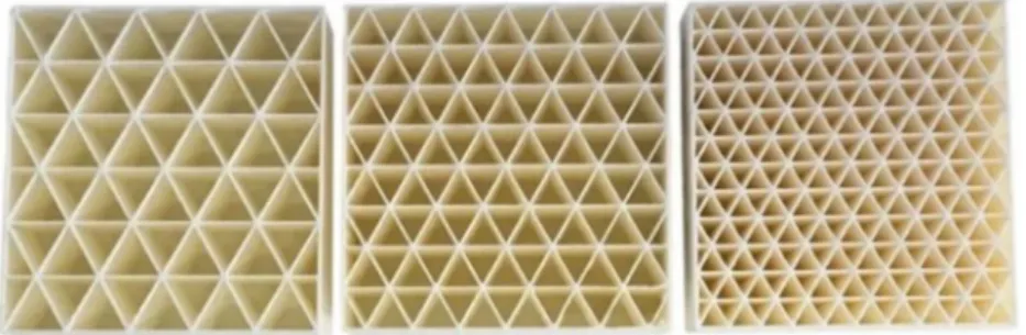
Numerical homogenization is an efficient method to deter-mine the effective macroscopic properties of periodic compos-ite materials. Only the unit cells (Fig.3) must be designed and are periodically repeated by the code into the 2D space. By assigning an extremely low Young’s modulus for the void regions, a single-phase cellular material can be represented. For this analysis, a MATLAB code from Andreassen and Andreasen (2014) is used. The 3D-printed infill pattern that is chosen is a pseudo-isotropic triangular pattern (see also Figs.2and3), meaning that their properties are very close to Fig. 2 PLA bricks printed with
different triangular infill densities on an Ultimaker 3, from left to right: 0.18, 0.22, 0.33
uniform in all orientations. Patterns that share this property are honeycomb patterns, tri-hexagonal patterns, or the 3D gyroid pattern. The structural material properties as well as their ther-mal conductivity properties are computed and compared with the SIMP and RAMP models. Additionally, the Hashin Shtrikman (HS) bounds are presented as well. These bounds are well-known in the theory of composites, as they represent the extreme effective properties of isotropic two-phase com-posites. In the limit when the properties of one of the phases (voids) are equal to 0, the HS upper bounds read as follows (Torquato et al.1998):
E* E0 ≤
x
3−2x ð3Þ
for Young’s moduli; λ*
λ0 ≤
x
2−x ð4Þ
for thermal conductivity. For the structural homogeniza-tion, this simplification can be made because the stiffness of the voids (air) is indeed (almost) 0. For the thermal interpola-tion model, the simplificainterpola-tion of (4) is not justified as the material properties of the voids are not 0 (the thermal conduc-tivity of air at atmospheric pressure is set to 0.025 W/mK). Therefore, its extended version (5) was used, which is math-ematically equivalent to the two forms of the well-known Maxwell–Eucken model (Hashin and Shtrikman1962).
λ*≤ 2λminþλ0−2 λmin−λ0 x 2λminþλ0þ λmin−λ0 x ð5Þ
4.1 Structural material properties
Although the homogenized material properties can be de-duced for any type of infill pattern or material, the presented interpolation model was determined for a triangular pattern made from PLA plastic. Some initial assumptions are given.
The elastic property, or Young’s modulus, of the PLA (E0) is 2500 MPa, while the voids (air) are set to a very low Young’s modulus of 0.001 MPa. The Poisson ratio (ν0) of the material is 1/3, and a plane stress relation is used. After the numerical analysis, the MATLAB code provides the user with a homog-enized stiffness matrix from which the following material characteristics can be deduced:Ex,Ey,Gxy,νxy, andνyx. Due to the pseudo-isotropy of the pattern, Young’s moduli in both normal directions are approximately equal and a link exists with the shear modulus (G). Finally, simplifyingνxyandνyxto
ν0
, Young’s modulus of the homogenized material is calculat-ed as the average ofEx,Ey, and 2 (1 +ν0)Gxy.
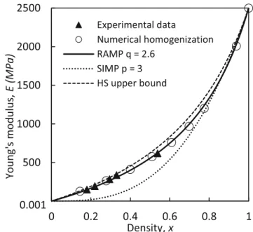
Figure4presents the results of the numerical homogeniza-tion study for a range of different element densities. They are presented as circles on the graph and compared with several experimental results (triangles). The size of the experimental samples is 50 × 50 × 20 mm, and the samples were 3D printed in white PLA on an Ultimaker 3. Each density was printed four times. Two samples were printed with a nozzle width of 0.4 mm and another set was printed with a nozzle width of
Fig. 4 Results of the experimental and numerical studies compared with the RAMP and SIMP models, and the Hashin–Shtrikman upper bound for an isotropic material with Poisson ratio 1/3 mixed with void Fig. 3 Unit cell topologies with
different infill densities (from left to right: 0.14, 0.28, 0.40). The unit cell is finely discretized by a mesh of 420 × 420 elements
0.8 mm. As can be seen in the graph, a good fit between both results exists. The HS upper bound is displayed by a dashed line, while the SIMP model (power law) function is shown by a dotted line. For use in the topology optimization study, the best fitting curve is obtained using a RAMP (Rational Approximation of Material Properties) model with aq-value of 2.6 (Stolpe and Svanberg2001). The mathematical function used in the topology optimization study is therefore given by the following equation:
Eeð Þ ¼xe Evoidþ xe 1þqð1−xeÞ E 0−E void w: Evoid¼0:001;E0¼2500;andq¼2:6 ð6Þ
4.2 Thermal material properties
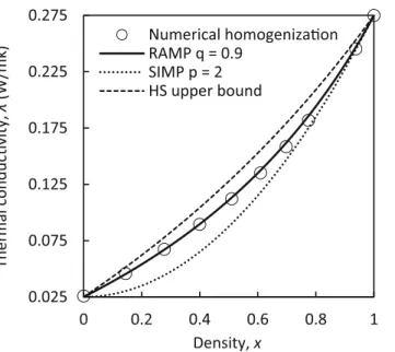
The numerical homogenization for the calculation of the ther-mal conductivities is very analogous to that of the elastic problem, though it is enough to solve for a scalar field—the temperature. Since air becomes trapped in the internal voids, the infill pattern largely increases the material’s thermal insu-lation quality. Logically, the lower the element’s density, the lower will be its thermal conductivity through the PLA. The thermal conductivity of the solid PLA (λ0) used in this study is 0.275 W/mK, while the thermal conductivity of the cavity air (λmin) is set to 0.025 W/mK. Figure5presents the results of the numerical homogenization study. As can be seen, the nu-merical data points are close to the HS upper bound, and the best fitting RAMP curve is found for aq-value of 0.9.
Because the MATLAB code by Andreassen and Andreasen only takes into account heat flow by conduction, the air inside the cavities is regarded as being completely stationary. This sim-plification is of course an inaccurate assumption. The thermal performances will be influenced by convection and radiation inside the air cavities (Bekkouche et al.2013). To cope with this problem, an additional study is carried out conforming with EN ISO 10077-2 (International Organization for Standardization, 2012). Subsequently, the heat flow by conduction, convection, and radiation in the air cavity is analyzed. The cavities of the infill pattern are considered unventilated and the emissivity of the PLA is set to 0.90. Also, a link is made between the infill pattern density and the nozzle width. Because the focus of this paper is on large-scale 3D printing applications, the nozzle sizes that are included in this study are 4 mm, 2 mm, and 0.8 mm. However, only a nozzle size of 4 mm is used for the case study. The resulting interpolation schemes can be found on Fig.6.
Results show that the heat flow is largely affected by the size of the cavity. The value of the equivalent thermal conduc-tivity for lower densities has increased significantly. This is due to the fact that low-density elements can create larger voids, where thermal convection reduces the thermal insula-tion quality. Addiinsula-tionally, three different results can be seen. These show the effect of the different nozzle sizes. For iden-tical infill densities, the size of a cavity is larger when a larger nozzle is used. Consequently, a small nozzle will give better thermal properties. It can be noted that this convection prob-lem can be avoided by filling the voids with additional insu-lation material. Although this might be achieved in certain cases, it brings difficulties to the manufacturing process, and is hard to achieve for large-scale components.
0.025 0.075 0.125 0.175 0.225 0.275 0 0.2 0.4 0.6 0.8 1 Thermal conducvity, λ (W/mk) Density, x Numerical homogenizaon RAMP q = 0.9 SIMP p = 2 HS upper bound
Fig. 5 Results of the numerical homogenization study compared with a RAMP model, a SIMP model, and the Hashin–Shtrikman upper bound for an isotropic material mixed with air cavities
0.0
0.2
0.4
0.6
0.8
1.0
0
0.2
0.4
0.6
0.8
1
Therm
a
l conducvity,
λ
(W/mK)
Density,
x
Numerical Homogenizaon
Nozzle 4 mm
Nozzle 2 mm
Nozzle 0.8 mm
Fig. 6 Adjusted material interpolation scheme for the thermal optimization problem, considering thermal convection and radiation in the cavities, versus the RAMP approximation of the numerical homogenization study
To transform the results to the optimization process, a mathematical function is mapped onto these results. The resulting interpolation schemes are all based on the same basic function, but with different parameters for A, B, and C. The element thermal conductivity is presented as follows:
λeð Þ ¼xe λminþ Axe2þBxeþCxe−1 λ0−λ min w: λmin¼0:025 and λ0¼0:275 ð7Þ
The specific input for parameters A, B, and C can be found in Table 1 and is constructed using the method of least squares. No physical experiments regarding the thermal prop-erties are performed for this study.
Finally, it is worth mentioning that no data are presented for densities lower than 0.05, because the manufacturing of such low densities is deemed unrealistic, even for large-scale pur-poses. In the limit, whenxgoes to 0, the equivalent thermal conductivity depends on the size of the void that is being created. Although this value can be determined using bound-ary tracing techniques, this concept is not applied in this study. As such, the maximum value for the thermal conductivity was 0.42 W/mK, and the lower variable bound is adjusted.
4.3 Conclusion
For each design variable, three interpolation functions are de-termined. A first relation is made between the design variables and their stiffness,Ee(xe). Secondly, a match is found for their thermal insulation quality,λe(xe). And finally, a link also exists between the density and its volume, whereVe(xe) is the ma-terial volume that linearly depends onx.
5 Case study
The problem that is studied here is the design of a ficti-tious roof structure for a—to be 3D printed— polymer-based pavilion. This roof structure is shaped by several 6-m-long elements, supported on the ends, and loaded by a uniformly distributed load (top and bottom surfaces). The boundary conditions and mechanical loads are pre-sented in Fig. 7. As can be observed, only half of the domain is modeled due to symmetry. The domain is
discretized using a structured grid of 600 × 120 square finite elements with a unit length of 5 mm. The thickness of the design domain is 100 mm. The magnitude of the external loads isq= 1.5 N/mm, acting in the -Y direction. This value was derived from a 300 kg/m2plane load, be-ing distributed over both the top and bottom surfaces. Additionally, also thermal boundary conditions are applied to the top and bottom surfaces. The inner boundary has a temperature of 20 °C, while the outer boundary has a temperature of 0 °C. The temperature difference between the bottom (inner surface) and the top (outer surface) is thus 20 K. Furthermore, the filter radius rminis set to 4.0 and the allowable volume fraction is 50%.
The results are presented using a grayscale (0–1) color map. The voids are displayed in white and the solid material is shown as black. The intermediate densities thus represent the infill pattern that should be used. The mid-beam deflections and the thermal transmittance (equivalent U-value) are also calculated to provide infor-mation about the structure’s structural and thermal per-formances. For the calculation of the thermal transmit-tance, the exchange of thermal energy between the body’s surface and its surroundings is also considered. The values for the heat transfer coefficients are hi= 7.7 W/(m2K) and ho= 25 W/(m2K).
The first set of results of the topology optimization study is now presented. These results are created using the thermal interpolation function for a nozzle size of 2 mm. The solutions are spread across two groups. The first group presents the optimal distribution of material in function of only one of the two sub-objectives. The first solution (Fig.8a) solves for maximum stiffness, while the second (Fig. 8b) solves for maximum thermal efficiency. The second group presents the multi-physics optimization study with the weighted-sum objective (see Fig.9).
As can be observed, the optimized solution in Fig. 8a does not include any intermediate densities. A very stiff frame-like structure is created with a maximum (mid-beam) deflection of 16.4 mm. This results in an overly good deflection state of L/367, which is below the required limit L/300. However, theU-value of the beam element is Fig. 7 Setup for the topology optimization study of a single-span simply supported beam, subjected to uniformly distributed loads and a temperature difference of 20 K between the top and bottom surfaces. Only the right symmetric half is presented
Table 1 Parameter set for thermal interpolation model
Nozzle size (mm) A B C
0.8 0.628 0.328 0.024
2 0.787 0.136 0.078
very high (0.43 W/m2K). In contrast, the solution present-ed in Fig.8bonly contains one type of grayscale material. The reason for this is obvious, asx= 0.35 offers the lowest value for the equivalent thermal conductivity in the case: nozzle width = 2 mm. Would this study be conducted for the other nozzle sizes, the results would also converge to element densities that have the lowest value for the thermal conductivity (nozzle 4 mm:x= 0.45; and nozzle 0.8 mm: x= 0.20). Although theU-value is now very good (0.19 W/ m2K), this comes at the cost of a largely reduced stiffness; the mid-beam deflection now reads 92.0 mm (L/65).
The optimized results presented in Fig.8 are the most extreme solutions. They define the outer limits of the multi-physics (also multi-objective) optimization problem. The first solution gives the stiffest roof component, while the second is the most thermally efficient structure. Increasing the thermal performance of the first solution will always decrease its stiffness, while increasing the stiffness of the second result will always decrease its ther-mal efficiency. The goal of the subsequent multi-objective optimization studies is to limit this performance deteriora-tion and demonstrate the benefits of a multi-physics
topology optimization study. An optimal trade-off is sought, while varying the importance of each of the sub-objectives.
Figure 9a shows the first optimized solution where both objectives are active. The importance of the ther-mal objective is introduced, adding only 0.8 mm to the beam’s deflection. A mixed material layout distribution can be observed, where not only solid and void regions are created, but also intermediate material-density re-gions are present. Most notable is that by allowing this small reduction in stiffness, the U-value of this beam element has become much better. For a 5% increase in deflection, the U-value has improved by 37%. This nicely exposes the benefits of a multi-physics topology optimization study, where a much more beneficial de-sign can be found by analyzing not only one, but mul-tiple physics at the same time.
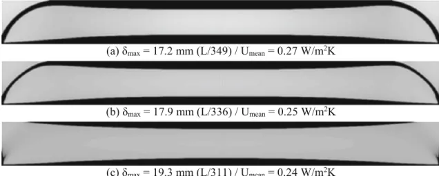
For the subsequent solutions, the importance of the ther-mal objective is gradually increased to further lower theU -value so that it meets the current minimal requirements according to existing engineering codes (equivalentU -val-ue roof < 0.24 W/m2K). The result presented in Fig. 9c
Fig. 9 Second set of results showing pareto-optimal solution of the multi-physics (multi-objective) topology optimization study
finally hits the soft spot; a U-value of 0.24 W/m2K is reached and the mid-beam deflection arrives just below the required limit state of L/300.
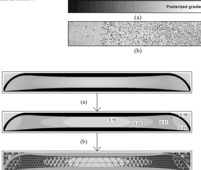
Finally, there is one task remaining: the transforma-tion of the mathematically optimized solutransforma-tion into a 3D-printable structure with different types of infill densities. Fig. 11 Schematic illustration of the method that is used to transform the mathematical solution into a structure with different types of infill densities. Post-processing: image posterization (a) and infill pattern generation (b)
Fig. 10 Image posterization (a), and functionally graded concrete (b) (Herrmann and Sobek2017)
Several strategies can be employed; however, we pres-ent a simple approach of which a schematic overview can be found in Fig. 11. The process that is used is called image posterization, which entails a conversion of the continuous gradation of tone to several regions of fewer tones.
In this paper, this is accomplished by decreasing the image’s apparent bit depth (Fig. 10a) and performed because the slicing algorithm does not function with a continuous color gradation at this moment. However, such algorithms are in active development (Li et al. 2018). Also, for example, in concrete 3D printing appli-cations, functionally graded concrete (Fig. 10b) is being developed (Herrmann and Sobek 2017) and supported by advancements in active rheology control (De Schutter and Lesage 2018). Here the continuous density distribution could then serve as a direct input (Fig. 11). A functionally graded concrete girder with weight opti-mization for a uniformly distributed load can be seen in Fig. 12.
6 Conclusions
In this paper, a novel multi-physics interpolation model was proposed that can link 3D printing technology to topology optimization. The structural and thermal material properties of triangular infill patterns were analyzed and coupled with the mathematical design of the interpolation functions. Taking into account, among other things, thermal convection in the air cavities, a realistic penalization scheme was created.
Subsequently, using this novel interpolation scheme, a roof component was optimized, and a design was generated with improved thermal and stiffness properties. Finally, the optimi-zation study was able to generate several sets of optimized topologies with different trade-offs between structural integri-ty and thermal efficiency. This was realized by implementing a weighted-sum multi-objective.
Future studies could analyze the influence of different infill patterns such as honeycomb structures or tri-hexagon patterns. Especially the analysis of 3D-infill patterns such as cubic, tetrahedral, or gyroid patterns could prove to offer valuable benefits for multi-physics topology optimization for 3D-printable building structures. It could strengthen the already existing and strong connection between topology-optimized design and additive manufacturing. Additionally, concrete 3D printing could offer solutions to enable a shift from“stepwise gradation”to a virtually seamless gradation pattern (Fig.12), and would enable the production of complex geometries, where relatively few adjustments must be made to comply with the manufacturing constraints. Therefore, multi-physics topology optimization looks very promising and could poten-tially revolutionize certain design methods for building engineering.
Another exciting opportunity in multi-physics topology op-timization can be found by studying different aspects, other than structural and thermal properties. For example, the addi-tion of vibraaddi-tion reducaddi-tion in structures, or the optimizaaddi-tion of moisture transport to the current approach, could further un-cover many unexplored possibilities.
Acknowledgments The authors thank Krister Svanberg for providing the MMA optimizer code.
Funding information This research was supported by Ghent University.
Compliance with ethical standards
Conflict of interest The authors declare that they have no conflict of interest.
References
Allaire G (2015) A review of adjoint methods for sensitivity analysis, uncer-tainty quantification and optimization in numerical codes. Ingénieurs de l’Automobile, SIA 836:33–36
Amir O, Shakour E (2017) Simultaneous shape and topology optimization of prestressed concrete beams. Struct Multidiscip Optim 57(5):1831–1843 Andreassen E, Andreasen C (2014) How to determine composite material properties using numerical homogenization. Comput Mater Sci 83:488– 495
Andreassen E, Clausen A, Schevenels M (2011) Efficient topology optimi-zation in MATLAB using 88 lines of code. Struct Multidisc Optim 43:1 Baich L, Manogharan G, Marie H (2015) Study of infill print design on production cost-time of 3D printed ABS parts. Int J Rapid Manuf 5(3/4):308
Bekkouche SM, Benouaz T, Cherier MK, Hamdani M, Yaiche MR, Benamrane N (2013) Thermal resistances of air in cavity walls and their effect upon the thermal insulation performance. Int J Energy Environ 4(3):459–466
Bendsøe MP (1989) Optimal shape design as a material distribution problem. Struct Multidiscip Optim 1(4):193–202
Bendsøe MP, Kikuchi N (1988) Generating optimal topologies in structural design using a homogenization method. Comput Mothod Appl M 71(2):197–224
Bendsøe M, Sigmund O (1999) Material interpolation schemes in topology optimization. Arch Appl Mech (Ingenieur Archiv) 69(9–10):635–654 Bendsøe M, Sigmund O (2003) Topology optimization: theory, methods
and applications. Springer, Berlin
Bruggi M, Taliercio A (2013) Design of masonry blocks with enhanced thermomechanical performances by topology optimization. Constr Build Mater 48:424–433
Carstensen J, Ganobjak M (2018) Topology-optimized design of building component with improved thermal and stiffness properties. Proceedings of the IASS Symposium 2018
De Schutter G, Lesage K (2018) Active control of properties of concrete: a (p)review. Mater Struct 51(5):123
Deaton J, Grandhi R (2013) A survey of structural and multidisciplinary continuum topology optimization: post 2000. Struct Multidiscip Optim 49(1):1–38
Fredricson H (2005) Topology optimization of frame structures—joint penalty and material selection. Struct Multidiscip Optim 30:193 Gosselin C, Duballet R, Roux P, Gaudilliere N, Dirrenberger J, Morel P
(2016) Largescale 3D printing of ultrahigh performance concrete -a new processing route for -architects -and builders. M-ater Des 100: 102–109
Hager I, Golonka A, Putanowicz R (2016) 3D printing of buildings and building components as the future of sustainable construction? Proc Eng 151:292–299
Han Y (2016) Influence of 3D printing infill patterns on the effective thermal properties. Journal of Purdue Undergraduate Research 6:89 Hashin Z, Shtrikman S (1962) A variational approach to the theory of the effective magnetic permeability of multiphase materials. J Appl Phys 33:3125–3131
Hens H (2011) Applied building physics. Ernst & Sohn, Berlin H e r r m a n n M , H a a s e W ( 2 0 1 3 ) Tr a g v e r h a l t e n b i e g e - u n d
querkraftbeanspruchter Bauteile aus funktional gradiertem Beton. Beton- Stahlbetonbau 108(6):382–394
Herrmann M, Sobek W (2017) Functionally graded concrete: numerical design methods and experimental tests of mass-optimized structural components. Struct Concr 18(1):54–66
International Organization for Standardization (2012) ISO 10077-2: ther-mal performance of windows, doors and shutters - calculation of thermal transmittance - part 2: numerical method for frames Jiang R, Kleer R, Piller F (2017) Predicting the future of additive
manufacturing: a Delphi study on economic and societal implica-tions of 3D printing for 2030. Technol Forecast Soc Chang 117:84– 97
Joosten SK (2015) Printing a stainless steel bridge: An exploration of structural properties of stainless steel additive manufactures for civil engineering purposes (Master). TUDelft.http://resolver.tudelft.nl/ uuid:b4286867-9c1c-40c1-a738-cf28dd7b6de5
Li D, Liao W, Dai N, Dong G, Tang Y, Xie Y (2018) Optimal design and modeling of gyroid-based functionally graded cellular structures for additive manufacturing. Comput Aided Des 104:87–99
Lim S, Buswell RA, Le TT, Austin SA, Gibb AGF, Thorpe T (2012) Developments in construction-scale additive manufacturing pro-cesses. Autom Constr 21:262–268
Petrick I, Simpson T (2013) 3D printing disrupts manufacturing: how economies of one create new rules of competition. Res Technol Manag 56(6):12–16
Royal Academy of Engineering (2013) Additive Manufacturing: Opportunities and Constraints. London: Royal Academy of Engineering.https://www.raeng.org.uk/publications/reports/ additive-manufacturing
Sanders (2017)
https://wyss.harvard.edu/media-post/3d-printing-ceramic-foam/. Accessed 25 Oct 2018
Sigmund O, Maute K (2013) Topology optimization approaches—a com-parative review. Struct Multidiscip Optim 48:1031–1055
SOM (2018) AMIE 1.0. Retrieved fromhttps://www.som.com/projects/ amie. Accessed 25 Oct 2018
Stolpe M, Svanberg K (2001) An alternative interpolation scheme for minimum compliance topology optimization. Struct Multidiscip Optim 22(2):116–124
Suiker A (2018) Mechanical performance of wall structures in 3D print-ing processes: theory, design tools and experiments. Int J Mech Sci 137:145–170
Svanberg K (1987) The method of moving asymptotes - a new method for structural optimization. Int J Numer Meth Eng 24(2):359–373 Torquato S, Gibiansky LV, Silva MJ, Gibson LJ (1998) Effective
mechan-ical and transport properties of cellular solids. Int J Mech Sci 40:71– 82
Vantyghem G, De Corte W, Boel V, Steeman M (2016) Structural and thermal performances of topological optimized masonry blocks. In: Asian Congress of Structural and Multidisciplinary Optimization 2016. Nagasaki
Vantyghem G, Boel V, Steeman M, De Corte W (2019) Multi-material topology optimization involving simultaneous structural and ther-mal analyses. Struct Multidiscip Optim 59:731
Ventola CL (2014) Medical applications for 3D printing: current and projected uses. Pharm Ther 39(10):704–711
Zhu J, Zhang W, Xia L (2015) Topology optimization in aircraft and aerospace structures design. Arch Comput Methods Eng 23(4): 595–622
Publisher’s note Springer Nature remains neutral with regard to jurisdictional claims in published maps and institutional affiliations.