White Rose Research Online URL for this paper:
http://eprints.whiterose.ac.uk/89009/
Version: Accepted Version
Article:
Querin, OM, Victoria, M, Díaz, C et al. (1 more author) (2015) Layout optimization of
multi-material continuum structures with the isolines topology design method. Engineering
Optimization, 47 (2). 221 - 237. ISSN 0305-215X
https://doi.org/10.1080/0305215X.2014.882332
[email protected] Reuse
Unless indicated otherwise, fulltext items are protected by copyright with all rights reserved. The copyright exception in section 29 of the Copyright, Designs and Patents Act 1988 allows the making of a single copy solely for the purpose of non-commercial research or private study within the limits of fair dealing. The publisher or other rights-holder may allow further reproduction and re-use of this version - refer to the White Rose Research Online record for this item. Where records identify the publisher as the copyright holder, users can verify any specific terms of use on the publisher’s website.
Takedown
If you consider content in White Rose Research Online to be in breach of UK law, please notify us by
Layout Optimization of Multi-Material Continuum Structures
with the Isolines Topology Design Method
Osvaldo M. Querin1, Mariano Victoria2, Concepción Díaz2, and Pascual Martí2
1
School of Mechanical Engineering. University of Leeds
Leeds LS2 9JT, United Kingdom
e-mail: [email protected]
web: http://www.mech-eng.leeds.ac.uk/menomq/
2
Departamento de Estructuras y Construcción. Universidad Politécnica de Cartagena
Campus Muralla del Mar. C/Doctor Fleming, s/n. 30202 Cartagena, España
e-mail: [email protected]; [email protected]; [email protected]
web: http://www.upct.es/~deyc
Keywords: Layout optimization, multi-material, ITD algorithm, isolines, continuum
structures
Abstract:
A heterogeneous or multi-material object is one made from different materials
which are distributed continuously or discontinuously and where its properties can be
adjusted by controlling the material composition, microstructure and geometry of the
object. The development of manufacturing technologies such as rapid prototyping can
eliminate the high cost of tooling and can offer the possibility to make multi-materials
structures. However the ability to design them is not a trivial task and requires the
algorithm which allows it to obtain multi-material designs. Four examples of the
topology design of 2D continuum structures are presented to demonstrate that the ITD
algorithm is an efficient and reliable method to carry out the layout optimization of
multi-material continuum structures.
1 INTRODUCTION
In the past, the intuition and experience of designers played a key role in structural
design. The last few decades have seen remarkable advances made in topology
optimization, which provides conceptual layouts for a given design space and specified
boundary conditions. There are a lot of methods, but these can be divided into one of
two types: 1) Those with a mathematical basis (Homogenization and Solid Isotropic
Microstructure with Penalization (SIMP), Level set method (LSM); and 2) those based
on heuristics (Soft Kill (SK), Hard Kill (HK), Evolutionary Structural Optimization (ESO),
Additive ESO (AESO), Bidirectional ESO (BESO), Reverse Adaptivity (RA), etc). The
aim of these methods is to support the intuition and the experience of a designer. In
addition, most of these methods are focused on the optimization of traditional
structures consisting of one material.
A heterogeneous or multi-material object is referred to as a solid object made of
different materials distributed continuously or discontinuously and its properties can be
adjusted by controlling the material composition, microstructure and the geometry of
the object (Jadayil 2011).
In many applications, the object should have certain characteristics to be able to
develop its function as: Heat resistance, anti-oxidation properties, high yield stress or
ultimate tensile strength, etc. Such properties may not be obtained by using single or
The development of new manufacturing technologies such as rapid prototyping
(Bhashyam et al. 2000) or solid free form fabrication (Beaman et al. 1997, Jakubenas
et al. 1998), and the use of new materials like composites (Blasques and Stolpe 2012)
requires new optimization techniques. These emerging manufacturing technologies
eliminate the high cost of tooling and design changes or material substitution and offer
the possibility to achieve multi-materials structures. However, this makes it much more
difficult to design objects just by intuition. Hence, new optimization algorithms are
needed to provide designs which take into account all the different aspects of such a
problem (König and Fadel 1999).
Objects with varying properties across spatial domain are commonly used in
aerospace, biomedical, civil, geophysical and nano-scale structures. In these
applications, the performance objectives are reached due to the capability of varying
material properties globally and locally across the design domain.
Thomsen (1992) maximized the integral stiffness of a structures composed of one
or two isotropic materials using the homogenization technique. Material was modelled
by a second rank composite using the concentration and orientation of the composite
as design variables.
Sigmund and Torquato (1997) presented a topology optimization method to design
material microstructures with extreme thermoelastic properties. The method consists in
finding the distribution of material phases that optimizes the isotropic thermal
expansion (i.e. the sum of the thermal strain coefficients in the horizontal and the
vertical directions) subjected to constraints, such as elastic symmetry or volume
fractions of the constituent phases, within a periodic base cell. The effective properties
Sigmund (2001) demonstrated that topology optimization can be used as a
systematic tool for the design of two-material MicroElectroMechanical Systems
(MEMS). The topology optimization method was extended to multiple materials by
introducing two design variables per element. One variable determines whether there is
material in the element or not and the other variable determines the type of material.
The interpolation of the material properties was made using a hybrid scheme, where
the power-law approach was used to interpolate between void and material and a
weighted average of the upper and lower Hashin-Shtrikhman bounds (Hashin and
Shtrikman 1963) were used to interpolate between the material types.
Yin and Ananthasuresh (2001) proposed a new material interpolation model, called
the peak function model. By using the peak function and the optimality criteria method,
they synthesized compliant mechanisms with multiple materials with and without the
material resource constraint.
Saxena (2002) discussed the discrete density parameterization with
multiple-material handling in topology optimization of compliant mechanisms. Genetic algorithm
was the search algorithm using fitness function values to guide a probabilistic search
towards a possible global optimum.
Yulin and Xiaoming (2004) applied LSM to a general optimization problem with
multi-materials and multi-constraints, such as a stiff structure design, a compliant
mechanism design or a material design by using the different material representation
models.
Wang and Wang (2004) addressed the problem of structural shape and topology
optimization in a multi-material domain. The LSM was used as an alternative approach
Jung and Gea (2006) proposed a new multi-material model to formulate the
topology optimization problem for energy absorption. A three-phase material model for
topology optimization was derived to accommodate two conflicting design objectives: 1)
Minimize the mean compliance; and 2) Maximize the strain energy for energy
absorption.
Zhou and Wang (2007) introduced a phase field model for the optimization of
multi-material structural topology based a modified Cahn-Hilliard theory. They treated
the problem of minimizing the mean compliance of a multi-material structure as a
thermodynamic system with mass concentration as phase field variable.
Huang and Xie (2009) developed a new and generalized BESO method with a
penalization parameter for continuum structures with one or multiple materials utilizing
a material interpolation scheme.
Gao et al. (2010) investigated the topology optimization problem of multiple
materials with mass constraint. Two types of material interpolation schemes named
Generalized Solid Isotropic Material with Penalization (GSIMP) and Uniform
Interpolation Model (UIM) were considered.
Ramani (2010) presented an algorithm which uses material as a discrete variable
in multi-material topology optimization and thus provides an alternative to traditional
methods using material interpolation and level-set approaches. The algorithm
computes pseudo-sensitivities of the objective and constraint functions to discrete
material changes. These are used to rank elements, based on which fraction of the
elements are selected for material ID modification during the optimization iteration.
Subsequently, a heuristic approach to handle strength constraints based on the
Luo et al. (2012) presented a topology optimization methodology considering
non-probabilistic reliability for the design of two-material continuum structures whose
objective was to distribute a given amount of two candidate materials into the design
domain for acquiring the maximum stiffness while satisfying the reliability requirements.
Blasques and Stolpe (2012) introduced a novel approach for the simultaneous
optimization of the topology and laminate properties in the structural design of
laminated composite beam cross sections. The optimization is based on a
multi-material topology optimization model in which the design variables represent the
amount of the given materials in the cross section. Existing material interpolation,
penalization, and filtering schemes were extended to accommodate any number of
anisotropic materials.
This article presents the extension of the Isolines Topology Design (ITD) algorithm
(Victoria et al. 2009) to the desig multi-material structures. The method of determining
the isolines is given, together with four examples to show the effectiveness of the
algorithm. The results show the usefulness of ITD to provide quality solutions with very
detailed shapes, without the need to interpret the design.
2 TOPOLOGY DESIGN WITH MULTI-MATERIALS TECHNIQUES
Currently, the most used techniques for topology design of continuum structures
using heterogeneous or multiple materials are: 1) Material interpolation schemes (Yin
and Ananthasuresh 2001, Huang and Xie 2009, Gao et al. 2010, Luo et al. 2012,
Blasques and Stolpe 2012,); 2) Level-set models (Yulin and Xiaoming 2004, Wang and
Wang 2004, Zhuang et al. 2007); and 3) Phase-field schemes (Bourdin and Chambolle
In material interpolation schemes, the overall mechanical properties of a
multi-material object are commonly obtained using a “rule of mixture”. For the three-phase
material design with two solid materials and void, the following power-law interpolation
scheme is commonly used to obtain an artificial elasticity modulus
E
as
1,
2
1
2E
1
1
2
E
2
E
p
p
p (1)where
E
1 andE
2 are the moduli of the solid material phases,
1
0
,
1
and
2
0
,
1
are the design density variables, and p1 is the penalization parameter for the
intermediate densities. Others interpolation schemes are also in use, such as the
Halpin-Tsai composite model (Suresh and Mortensen 1988), Voigt-Reuss (Swan and
Kosaka 1997) and Hashin-Shtrikman (Sigmund 2001).
To model more than two phases using the LSM one may consider using multi-level
set functions to partition the whole material domain of the structure with each level set
representing a distinct material phase (Zhao et al. 1998, Tsai et al. 2001).
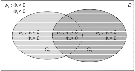
Wang and Wang (2004) proposed a new material model based on
multi-phase level-set scheme developed by Vese and Chan (2002).
They considered
m
level-set functions
x
D
R
i
m
i
:
1
,
,
(2)where D is the design domain.
Instead of using each level set to represent each distinct material phase as in the
partitioning level-set scheme, they allowed the interior regions of the zero-level sets of
material regions and denoted the disjointed but connected regions formed by these
boundaries
n
i1
i
byw
k, Eq. (3).l
k
w
w
w
D
nk k k
l
1
and
0
,
(3)where
n
is the number of materials.To illustrate this, an example of four material phases
n
4
and two level-set functions
m
2
is depicted in Fig. 1.Phase field schemes have for a long time been used as a practicable scheme for
interpreting a wide variety of material phenomena like diffusion and solidification. The
material may be solid or liquid of two or more phases. The usual problem is to
characterize the stability of such a system and to describe the interface between the
phases while the system undergoes a physical process to reach its stability (Zhou and
Wang 2007). In spite of the fact that there is a clear relationship between the problem
of topology optimization of a solid multi-material structure and a phase transition
system of material phases, the use of these schemes has not yet become popular.
Hence, there are few approaches in the literature Wang and Zhou (2004), Burger and
[image:9.595.160.436.316.461.2]Stainko (2006), and Takezawa et al. (2010).
3 FIXED GRID FINITE ELEMENT ANALYSIS
The Fixed Grid (FG) method was first introduced by Garcia and Steven (1999) as a
tool for numerical estimation of two-dimensional (2D) elasticity problems, and was
extended to three-dimensional (3D) structures like Garcia et al. (2004, 2005), etc. The
benefits of using FG-Finite Element Analysis (FEA) over conventional FEA in this work
are that: 1) FG does not need a fitted mesh to discretize the analysis domain; 2) The
boundary of the design is disassociated from the mesh (Garcia and Steven 1999); 3)
Designs using FG-FEA do not contain checkerboard patterns, making the design more
reliable for manufacture (Maan et al. 2007); and 4) Solution time is significantly
reduced (Garcia and Steven 2000). In FG-FEA, the elements are in a fixed position and
have the real design superimposed on them. This means that there are elements which
lie Inside (I), Outside (O), or on the Boundary (B) of the design.
The elemental stiffness matrix
K
e is given by Eq. (4).
1
0
if
1
0
if
1
if
O I B O I e e e e e e
K
K
K
K
K
K
(4)where
e is the design fraction inside the element,K
I is the element stiffness matrixfor an element inside,
K
O is the element stiffness matrix for an element outside, andB
K
for an element boundary. NormallyI 6
O 10 K
K .
In this work, the criterion value in each element
eis calculated using Eq. (5)
G nGwhere
n
G is the number of the Gauss points in the element, andw
is the weightingfactor for each Gauss point.
The criterion value at the i node of an element
in is determined by Eq. (6)N
N
e e n n
i
i
1
(6)where i is the ithnode number of an element, ne i
is the nodal criterion value at nodei for each element surrounding that node, and N is the number of elements
connected to that node. The nodal value is determined from the criterion values at each
Gauss point extrapolated to the nodes using the shape functions of the element.
4 MULTI-MATERIAL DESIGN WITH ISOLINES
The use of isolines/isosurfaces in 2D/3D respectively to obtain the optimum design
of structures has been used in several studies (Woon et al. 2003, Cui et al. 2003,
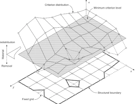
Koguchi and Kikuchi 2006). The ITD is an iterative algorithm which redistributes (adds
and removes) material inside of a design domain until it reaches a desired volume
fraction. The redistribution process consists of the following four steps: 1) Obtain the
design criterion distribution within the design domain; 2) Determine the Minimum
Criterion Level (MCL), where its intersection with the design criterion distribution
produces the new structural boundary, shown for a 2D continuum in Fig. 2; 3) Remove
all regions from the design domain where the criterion distribution is lower than the
MCL; and 4) This design modification requires the re-evaluation of the remaining
The MCL is calculated in each iteration and depends on both the distribution of the
design criterion and the volume of the design domain in that iteration given by Eq. (7)
i f i
i i
n
i
V
n
i
n
V
V
0 (7)where
V
i is the design volume in thei
th
iteration,
n
i is the total number of iterations,V
0is the initial volume, andVf is the final volume of the optimized structure.
Once the criterion has been calculated for each element in the design domain,
these are arranged in decreasing order of criterion value. An element by element
[image:12.595.83.518.98.433.2]volume summation of the ordered list is carried out until a volume is reached which is
between the summed and target volume depends on the size of the elements. The
criterion value of the next element in the ordered list is then used as the value for the
MCL.
4.1 Optimization problem
The optimization problem (Eq. 8 and 9) consisted of minimizing the difference
between the structure volume and a target volume subject to: 1) Structural equilibrium;
and 2) An inequality condition which must be satisfied by all the nodes of the structure.
Minimize:
f 0
V
V
(8)Subject to:
0 0
MCL
i P Ku
(9)
where:
K is the structure stiffness matrix
u
is structure displacement vectorP is the nodal load vector
MCL is the value of the minimum criterion level
i ith node which lies inside or on the boundary of the structure
i is the value of the design criterion in the ithnode
4.2 Criterion selection
The design criterion
e used in this work was the von Mises stress
vM , whichfor a two-dimensional continuum domain is calculated using Eq. (10).
2 2
2
vM
x
y
x
y3
xy
(10)4.3 Solid phase distribution to produce multi-material design
The idea to obtain multi-material stiff designs using the ITD algorithm is
straightforward; the high values of the design criterion must be supported by the solid
phases with the highest stiffness and vice versa. This is achieved by the 5 steps given
below:
1. Determine the volume
V
i of the design domain in the current ith iteration using Eq. (7) and obtain the MCL value
MCL
associated withV
i.
2. Arrange the j
-
material types
j
1
,
,
n
in decreasing order of stiffness value using the Young’s moduli. The greatest value of the Young’s modulusis termed
E
1 and the smallest value is termedE
n.3. Calculate the volume for every solid phase
Vj in the current ith
iteration,
using Eq. (11)
1
1
n j j i j jV
V
(11)where
j is the volume control weighting factor. Its value is initially proposedby the designer.
4. Calculate the MCL for each solid phase
MCL,j associated with Vi,j by Eq.(12), see Fig. 3.
5. Use the design fraction inside the element
e and the minimum criterionlevel for each phase
MCL,j
to determine material properties for everyelement
E
e by Eq. (13), see Fig. 3. otherwise 0 if e 0 j e E E E
n E E0 106 1 MCL, MCL, MCL,1 MCL,2 2 MCL,1 1 if if if n e n n e e j E E E E
(13) where: 0E
is the Young’s modulus for void phasen
E
is the Young’s modulus for n-material (i.e. the weakest material)j
E is the Young’s modulus of the jth material
e
is the elemental value of the criterion4.4 Minimum criterion level extraction
The procedure to generate the structural boundary depends on the determination
[image:15.595.140.452.457.617.2]of the MCL isoline. In order to determine the line segments that produce the profile of
the boundary, the contouring subroutine called Marching Triangles (MT) algorithm
(Hinton and Illingworth 1997) was implemented, since there are not ambiguities and the
isolines constructed are smooth.
The MT algorithm uses a divide-and-conquer approach, treating each finite
element independently as a triangular cell. In the case where the element shape is
quadrilateral, the element is divided into four triangular cells by introducing a point at
the centroid of the element. The criterion value of the central point is obtained by
calculating the average values from the four nodes of the original element. The basic
assumption of this algorithm is that a contour can only pass through a triangular cell in
a limited number of ways. This algorithm requires the value of the MCL together with
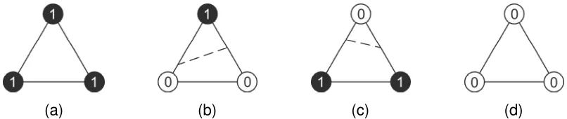
the value of the criterion at each corner of the cell, and consists of two steps: 1) Identify
from Fig. 4 the topological state of each cell; and 2) Determine the shape of the contour
of the MCL isoline through each cell. The interaction of an isoline through a triangular
cell can have a maximum of four different topological states, Fig. 4. The value (1) at a
corner means that its criterion value is greater than the MCL whereas a value of (0) at
a corner means that its criterion value is less than the MCL. When the corner in an
edge of a cell has different values (0 and 1 or vice versa) it indicates that the MCL
isoline intersects that edge, which is the case for topological states shown in Fig. 4b
and 4c. To find that intersection point, linear interpolation can be used. The shape of
the MCL isoline through the cell is then obtained by connecting these intersecting
points between the opposite edges as shown in Fig. 4b and 4c.
[image:16.595.96.499.638.723.2](a) (b) (c) (d)
4.5 Structural boundary stabilization
When the MCL is modified, the structural boundary changes and this affects the
criterion distribution. Therefore, before the next iteration is started, an iterative process
of reanalysis and material redistribution is carried out until the change in the domain
volume between successive boundary adjustments is less than a minimum volume
change limit
V
, given by Eq. (14). Typical values of the minimum volume change limit are around
V
%
1
%
.
%
1
100
1
i i
V
V
V
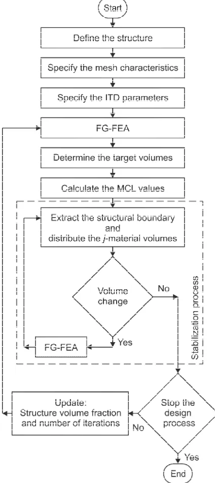
(14)5 THE ITD ALGORITHM FOR MULTI-MATERIAL DESIGNS
The modified ITD algorithm to carry out the layout optimization of multi-material
designs consists of the following eleven steps, a schematic representation of which is
given in Fig. 5.
1. Define the structure: design and non-design domains, total number of
materials
n
, material properties for every material
Ej , loads and supports.2. Specify the finite element mesh characteristics.
3. Specify the ITD parameters: design criterion
, volume control weighting factor
j , final design volume
Vf , total number of iterations
n
i , andminimum volume change limit
V
%
.4. Carry out a FG-FEA.
5. Determine the target volume for every material type
Vi,j .7. Extract the boundary of the structure and distribute the different materials.
8. If the percentage volume change is greater than the minimum volume
change limit
V
%
, go to step 9, otherwise go to step 10.9. Carry out a FG-FEA of the design domain and go to step 7.
10. If the total number of iterations
n
i has been reached, go to step 11,otherwise update the design volume, increment the iteration number
i
by 1 and go to step 4.6 EXAMPLES
To illustrate the ITD algorithm, four structures were studied and are presented here:
1) A short cantilever loaded at the lower free end; 2) A short cantilever loaded at the
middle free end; 3) A beam with a roller support; 4) A metallic insert. The FE used for
[image:19.595.189.401.100.575.2]the examples is the four-node plane stress quadrilateral element with four Gauss
integration points. Table 1 shows the colour legend used to represent the resulting
[image:20.595.157.435.169.222.2]multi-material designs.
Table 1.Colour legend for multi-material designs
Total number of material Material code number Void
1 2 3
2 Black Grey - White
3 Black Grey Light grey White
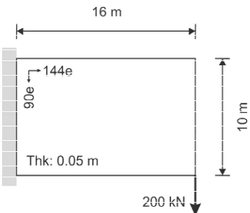
6.1 Short cantilever loaded at the lower free end
The first example is a short cantilever as is showed in Fig. 6. The design domain is
a rectangular area of 16×10 m and the thickness is 0.05 m. The mesh used for the
discretization of the design domain has 144×90 elements, fully clamped along the left
edge. A vertical load of 200 kN is applied at the lower free end in the downward
direction. Two materials were used with the Young’s moduli of
E
1
200
GPa
and
E
2
100
GPa
and the same Poisson’s ratio
0.3. The ITD parameters for thisexample were the total number of iterations
n
i
100
; final volumefractionVf V0 0.1and the minimum volume change
V
%
1
%
. To examine the effect of the volume control weighting factor
1 on the final design, eight cases wereinvestigated:
1
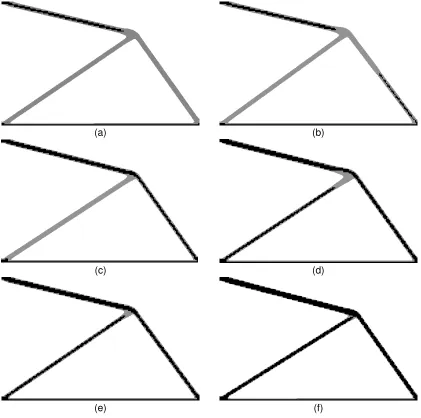
0.2; 0.3; 0.4; 0.5; 0.6; 0.66; 0.7; and 0.8. [image:20.595.207.389.564.719.2]Fig. 7 shows the resulting final topologies for each
1 value. This has shown thatthe optimal topologies (which suggest a four-bar truss design) are not affect
significantly by volume control weighting factor, except
1
0
.
8
(which suggest asix-bar truss design). The resulting multi-material design depicted in Fig. 7f is in good
agreement with that obtained by Luo et al. (2012).
(a) (b)
(c) (d)
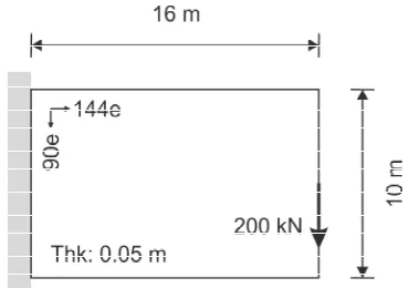
6.2 Short cantilever loaded at the middle free end
The design domain, support conditions, and mesh characteristics used in this
example are the same with the first example. A vertical load of 200 kN is applied at the
middle free end in the downward direction (Fig. 8). The ITD parameters were the total
number of iterations
n
i
100
, final volume fractionVf V0 0.1, the minimum volumechange
V
%
1
%
and the volume control weighting factor
1
0
.
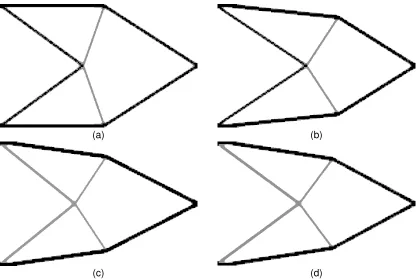
5
. To examine the effect of the material properties on the final design, four cases were investigated E1 =200 GPa with E2 = 150, 100, 50 and 20 GPa. The same Poisson’s ratio of 0.3 was
used.
[image:22.595.82.506.88.231.2](g) (h)
Fig. 7.Final designs for two-material scheme. Effect of different
1 on final design: (a) 0.2 (b) 0.3 (c) 0.4 (d) 0.5; (e) 0.6; (f) 0.66; (g) 0.7; (h) 0.8. [image:22.595.205.390.533.663.2]The resulting multi-material designs are depicted in Fig. 9. The resulting topologies
are not sensitive to the Young’s modulus value
E
2 , although it can be observed considerable differences between the final shape designs. The obtained designs are ingood agreement with those obtained by Wang and Wang (2005).
6.3 Beam with a roller support
The size of the beam is 24 m long by 4 m high with a thickness of 0.05 m (Fig. 10).
It has a fixed support in the bottom left-hand corner and a roller support on the
bottom-right corner. A vertical load of 200 kN in downward direction is applied at the centre of
the bottom edge. The mesh used has 360×60 elements. The ITD parameters used
were the total number of iterations
n
i
100
, final volume fractionVf V0 0.1, and theminimum volume change
V
%
1
%
. In this example, the influence of the material number was investigated for two cases: 1) A two-material scheme, withE
1
1
GPa
(a) (b)
[image:23.595.86.505.199.478.2](c) (d)
and
E
2
0
.
1
GPa
, and a volume control weighting factor
1
0
.
375
; and 2) Athree-material scheme, with
E
1
1
GPa
;E
2
0
.
5
GPa
andE
3
0
.
1
GPa
.
The second casewas studied for four different volume control weighting factors
1/
2/
3:
(a)0.2/0.4/0.4; (b) 0.2/0.6/0.2; (c) 0.4/0.2/0.4 and (d) 0.6/0.2/0.2. The same Poisson’s ratio
of 0.3 was used in both cases.
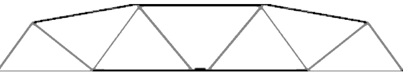
The final design for two-material scheme is shown in Fig. 11. The resulting design
depicts a sandwich structure with a stiff skin manufactured using material No.1 and a
soft truss core made in material No. 2. Note that, the resulting topology shows great
[image:24.595.144.453.251.367.2]agreement with the work of Huang and Xie (2009).
Fig. 10.Design domain for the beam with a roller support.
[image:24.595.102.500.569.644.2]As for the two-material case, the optimal designs obtained using the three-material
scheme are similar to the sandwich structure of (Fig. 11). The topology and shape of
the resulting designs are significantly sensitive to weighting factor combinations. Note
that, when material number increases the use of advanced technologies to
manufacture these designs plays a crucial role.
(a)
(b)
6.4 Metallic insert
A theoretical and experimental investigation by Nilsson (1989) on increasing the
bearing strength of composite bolted joints showed that by bonding a 2 mm circular
metallic insert in the hole, the compressive stresses at the hole boundary were reduced
by 50% and the failure load was increased by up to 55%. The purpose of this example
is to optimize the shape of the insert by an optimized material distribution using ITD
algorithm.
The geometric dimensions together with the loading and support conditions are
shown in Fig. 13a. Due to the symmetry conditions, the analysis was made using only
top-half of the domain using a regular rectangle mesh (Rispler and Steven 1995). The
mesh features were 93,956 elements, 94,605 nodes, 189,210 degrees of freedoms. To
ensure that the internal diameter remains unchanged in order to allow usage of
currently available fasteners the nearest region around the hole boundary is defined as
non-design domain. The bolt hole loading was represented by a linear pressure
distribution (Fig.13b). The ITD parameters for this example were the total number of
iterations
n
i
5
, final volume fraction Vf V0 1 and the minimum volume change
%
1
%
[image:26.595.97.502.121.189.2]
V
. The material properties used for the material No. 1 (aluminium) were (d)Fig. 12.Final designs for three-material scheme. Effect of differentweighting factor combinations
1/
2/
3 on design: (a) 0.2/0.4/0.4; (b) 0.2/0.6/0.2; (c) 0.4/0.2/0.4; (d)GPa
71
1
E
and
1
0
.
3
, and for the material No. 2 (composite) wereE
2
52
.
2
GPa
and
2
0
.
33
. Six area ratios of material No.1 (A1) with respect to hole area (AH)wereinvestigated: A1/AH= 0.25:1, 0.5:1, 0.75:1, 1:1, 2:1 and 3:1.
The resulting solutions are shown in Fig.14. In order to achieve a clearer designs
the black colour represents the aluminium material, the grey colour stands for the
non-design domain, and the composite material was not depicted. The obtained shape of
the inserts agrees with the solutions obtained by Rispler and Steven 1995.
[image:27.595.95.510.195.347.2](a) (b)
Fig. 13.Design domain for the metallic insert: (a) General dimensions and support conditions; (b) Detailed view of the loading.
7 CONCLUSIONS
This article presents an enhancement to the ITD algorithm which allows it to obtain
multi-material designs. The ITD is an iterative process, where the generation of new
contours allow the removal and redistribution of material. It allows for important
topology changes during the design process. The placement of the multiple materials
into the design is determined by the distribution of the design criterion (i.e. von Mises
stress) following the concept that the material of highest stiffness must support the
regions of the design with the highest design criterion.
Four examples of topology design of 2D continuum structures are presented to
demonstrate the applicability and effectiveness of the ITD algorithm. The main
conclusion of this work is that the ITD algorithm is an efficient and reliable method to
carry out the layout optimization of multi-material continuum structures.
(c) (d)
[image:28.595.121.470.104.375.2](e) (f)
Fig. 14.Final insert (full detail view) for different area ratios of material No. 1 (in black) with respect to hole area (A1/AH): (a)0.25:1, (b) 0.5:1, (c) 0.75:1, (d) 1:1, (e) 2:1 and (f) 3:1. The
ACKNOWLEDGEMENTS
This work was supported in part by the Departamento de Estructuras y Construcción at
the Universidad Politécnica de Cartagena (Spain) and the Ministerio de Economía y
Competitividad (Spain), via the research project DPI2011-26394. Its support is greatly
appreciated.
REFERENCES
Beaman JJ, Marcus HL, Bourell DL, Barlow JW, Crawford RH, McAlea KP. Solid freeform fabrication: a new direction in manufacturing: with research and applications in thermal laser processing. Kluwer Academic Publishers, 1997.
Bhashyam S, Shin KH, Dutta D. An Integrated CAD System for the Design of Heterogeneous Objects.Rapid Prototyping Journal,6(2): 119-135, 2000.
Blasques JP, Stolpe M. Multi-material topology optimization of laminated composite beam cross sections.Composite Structures,94: 3278-3289, 2012.
Bourdin B, Chambolle A. Implementation of an adaptive finite element approximation of the Mumford-Shah functional. Numer. Math.,85(4): 609-646, 2000.
Burger M, Stainko R. Phase-field relaxation of topology optimization with local stress constraints.SIAM J. Control Optim.45: 1447-1466, 2006.
Cui C, Ohmori H, Sasaki M. Computational morphogenesis of 3D structures by extended ESO method.Journal of IASS,44(141): 51-61, 2003.
Gao T, Zhang W, Duysinx P. Comparison of volume constraint and mass constraint in structural topology optimization with multiphase materials. In proceedings of the
2nd International Conference on Engineering Optimization, Lisbon, Portugal,
2010.
Garcia MJ, Ruiz OE, Ruiz LM, Querin OM. Fixed grid finite element analysis for 3D
linear elastic structures. In proceedings of the Computational Mechanics. WCCM VI in conjunction with APCOM’04, Beijing, China, 2004.
García MJ, Steven GP. Fixed grid finite element analysis in structural design and
optimization. In proceedings of the Second ISSMO/AIAA Internet Conference on Approximations and Fast Reanalysis in Engineering Optimization, 2000.
Garcia MJ, Steven GP. Fixed grid finite elements in elasticity problems. Engineering Computations,16(2):145-164,1999.
problems.International Journal of Computational Methods,2(4): 569-585, 2005.
Hashin Z, Shtrikman S. A variational approach to the theory of the elastic behaviour of multiphase materials. Journal of the Mechanics and Physics of Solids, 11(2): 127-140, 1963.
Hinton A, Illingworth J. Marching Triangles: Delaunay implicit surface triangulation. Technical Report CVSSP 01, University of Surrey, Guildford, UK, 1997.
Huang X, Xie YM. Bi-directional evolutionary topology optimization of continuum structures with one or multiple materials.Comput. Mech.,43: 393-401, 2009.
Jadayil WA. Revision of the Recent Heterogeneous Solid Object Modeling Techniques. Jordan Journal of Mechanical and Industrial Engineering,4(6): 779-788, 2011.
Jakubenas KJ, Sanchez JM, Marcus HL. Multiple material solid free-form fabrication by selective area laser deposition.Materials and Design,19(1-2): 11-18, 1998.
Jung D, Gea HC. Design of an energy-absorbing structure using topology optimization with a multimaterial model. Structural and Multidisciplinary Optimization,32: 251-257, 2006.
Koguchi A, Kikuchi N. A surface reconstruction algorithm for topology optimization. Engineering with Computers,20: 1-10, 2006.
König O, Fadel GM. Applications of Genetic Algorithms in the design of Multi-Material Structures Manufactured in Rapid Prototyping. In Proceedings of the Solid Freeform Fabrication Conference, Austin TX, 1999.
Luo Y, Kang Z, Yue Z. Maximal Stiffness Design of Two-Material Structures by Topology Optimization with Nonprobabilistic Reliability. AIAA Journal, 50(9): 1993-2003, 2012.
Maan FS, Querin OM, Barton DC. Extension of the fixed grid finite element method to
eigenvalue problems.Advances in Engineering Software,38: 607-617, 2007.
Nilsson S. Increasing strength of graphite/epoxy bolted joints by introducing and adhesively bonded metallic insert. Journal of composite materials, 2: 642-650, 1989.
Ramani A. A pseudo-sensitivity based discrete-variable approach to structural topology optimization with multiple materials. Structural Multidisciplinary Optimization. 41: 913-934, 2010.
Ramani A. Multi-material topology optimization with strength constraints.Structural and Multidisciplinary Optimization,43: 597-615, 2011.
Rispler AR, Steven GP. Shape Optimisation of Metallic Inserts In Composite Bolted Joints.In proceedings of the PICAST 2 – AAC 6, Melbourne, 1995.
Engineering Conference, Montreal, Canada, 2002.
Sigmund O, Torquato S. Design of materials with extreme thermal expansion using a three-phase topology optimization method.Journal of the Mechanics and Physics of Solids,45(6): 1037-1067, 1997.
Sigmund O. Design of multiphysics actuators using topology optimization part II: two material structures. Computer Methods in Applied Mechanics and Engineering,
190: 6605-6627, 2001.
Suresh S, Mortensen A. Fundamentals of Functionally Graded Materials, IDM Communications Ltd., 1988.
Swan CC, Kosaka I. Voigt–Reuss topology optimization for structures with linear elastic material behaviors,Int. J. Numer. Methods Engrg.,40: 3033-3057, 1997.
Takezawa A, Nishiwaki S, Kitamura M. Shape and topology optimization based on the phase field method and sensitivity analysis. Journal of Computational Physics,
229(7): 2697-2718, 2010.
Thomsen J. Topology optimization of structures composed of one or two materials. Structural Optimization,5: 108-115, 1992.
Tsai A, Yezzi A, Willsky AS. Curve evolution implementation of the Mumford-Shah functional for image segmentation, denoising, interpolation, and magnification. IEEE Trans. Image Process,10(8): 1169-1186, 2001.
Vese LA, Chan TF. A multiphase level set framework for image segmentation using the Mumford and Shah model.Int. J. Comput. Vision,50(3): 271-293, 2002.
Victoria M, Martí P, Querin OM. Topology design of two-dimensional continuum structures using isolines.Computer and Structures,87: 101-109, 2009.
Wang MY, Wang S. Bilateral filtering for structural topology optimization.Int. J. Numer. Meth. Engng.,63: 1911-1938, 2005.
Wang MY, Wang X. “Color” level sets: a multi-phase method for structural topology optimization with multiple materials. Comput. Methods Appl. Mech. Engrg., 193: 469-496, 2004.
Wang MY, Zhou SW. Phase field: A variational method for structural topology optimization.Comput. Model. Eng. Sci.,6: 547-566, 2004.
Woon SY, Tong L, Querin OM, Steven GP. Optimising topologies through a multi-GA System. In proceedings of the Fifth World Congress of Structural and Multidisciplinary Optimization (WCSMO 5), Lido di Jesolo, 229-230, 2003.
Yin L, Ananthasuresh GK. Topology optimization of compliant mechanisms with multiple materials using a peak function material interpolation scheme. Structural and Multidisciplinary Optimization,23: 49-62, 2001.
Zhao HK, Merriman B, Osher S, Wang L. Capturing the behaviour of bubbles and drops using the variational level set approach. J. Comput. Phys, 143: 495-518, 1998.
Zhou S, Wang MY. Multimaterial structural topology optimization with a generalized Cahn–Hilliard model of multiphase transition. Structural and Multidisciplinary Optimization,33: 89-111, 2007.