WORKFLOW AUTOMATION IMPROVES OPERATIONAL EFFICIENCY IN CONTROL CENTRES AND BEYOND.
Authors: Karl Herger, Otto Vollmeier and Franz Werner
Telegyr Systems Corp. (A Siemens Company), Switzerland
Summary
The final goal of deregulation of the electricity market is to give each customer the freedom to select energy suppliers of his own choice. In order to provide an attractive choice for customers, there has to be competition among power
producers and energy suppliers. Free competition requires energy suppliers to achieve a proper balance between quality of supply, economics and customer satisfaction.
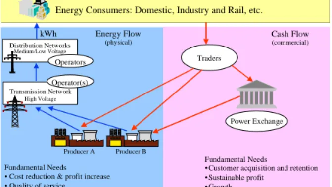
Focusing only on a low energy selling price would have a negative influence on quality of supply and therefore indirectly on customer satisfaction. Competition in the deregulated electricity market influences business structures as utility businesses are unbundled. In addition to existing transmission and distribution companies, new business units such as independent power producers (IPP), traders, brokers, etc. appear in the market. Business units are exposed to competition and are therefore interested in optimising all relevant work flows in order to reduce costs and increase efficiency.
Energy Consumers: Domestic, Industry and Rail, etc.
Producer B Producer A Transmission Network High Voltage Distribution Networks Medium/Low Voltage Traders Operators Fundamental Needs Fundamental Needs • Cost reduction & profit increase
• Quality of service
• Customer acquisition and retention • Sustainable profit • Growth Operator(s) Energy Flow (physical) Cash Flow (commercial) kWh Power Exchange
Figure 1: Deregulated market structure and players
Most of the existing business processes have to be adapted to the new realities.
Transmission and distribution companies are responsible for a secure network operation. Investments by these companies are monitored by a regulator in several countries. These companies are also obliged to optimise their business processes.
Optimisation and adaptation of business processes is often called business process reengineering.
The business processes within the various new companies are not fully established yet and are still subject to ongoing development. For this reason the question is “How can control centres be built in order to
a) deal with the realities of rapidly changing business process
b) protect short and medium term investments in data, application programs and other resources” ?
The paper describes possible solutions in respect of the structure of traditional and new applications, the optimisation of business processes and the required system techniques such as architecture, interfaces, etc.
In addition an example of business process reengineering, taken from a large electrical distribution company in Poland, is described in the appendix.
Business process reengineering starts with an analysis of the business process, followed by the creation of ideas and visions, and results in a set of USE CASES.
These USE CASES can be documented in a quality assurance manual or in corporate standard procedures. An alternative way of documentation is a Workflow Automation (WFA) tool. WFA tools are well established in documentation management systems but less established in control centre operation. This paper describes experience with the implementation of a WFA tool for a control room operator in an integrated network management and geographical information system environment.
In the context of energy deregulation and control centre technique the paper describes various innovation areas, the current state of the architecture & standards as well as an architectural outlook.
---WORKFLOW AUTOMATION IMPROVES OPERATIONAL EFFICIENCY IN CONTROL CENTRES AND BEYOND.
Authors: Karl Herger, Otto Vollmeier and Franz Werner
Telegyr Systems Corp. (A Siemens Company), Switzerland
ABSTRACT
The final goal of deregulation of the electricity market is to give each customer the freedom to select energy suppliers of his own choice. In order to provide an attractive choice for customers, there has to be competition among power
producers and energy suppliers. Free competition requires energy suppliers to achieve a proper balance between quality of supply, economics and customer satisfaction.
Focusing only on a low energy selling price would have a negative influence on quality of supply and therefore indirectly on customer satisfaction. Competition in the deregulated electricity market influences business structures as utility businesses are unbundled. In addition to existing transmission and distribution companies, new business units such as independent power producers (IPP), traders, brokers, etc. appear in the market. Business units are exposed to competition and are therefore interested in optimising all relevant work flows in order to reduce costs and increase efficiency.
Energy Consumers: Domestic, Industry and Rail, etc.
Producer B Producer A Transmission Network High Voltage Distribution Networks Medium/Low Voltage Traders Operators Fundamental Needs Fundamental Needs • Cost reduction & profit increase
• Quality of service
• Customer acquisition and retention • Sustainable profit • Growth Operator(s) Energy Flow (physical) Cash Flow (commercial) kWh Power Exchange
Figure 1: Deregulated market structure and players
Most of the existing business processes have to be adapted to the new realities.
Transmission and distribution companies are responsible for a secure network operation. Investments by these companies are monitored by a regulator in several countries. These companies are also obliged to optimise their business processes.
Optimisation and adaptation of business processes is often called business process reengineering.
The business processes within the various new companies are not fully established yet and are still subject to ongoing development. For this reason the question is “How can control centres be built in order to
a) deal with the realities of rapidly changing business process
b) protect short and medium term investments in data, application programs and other resources” ?
The paper describes possible solutions in respect of the structure of traditional and new applications, the optimisation of business processes and the required system techniques such as architecture, interfaces, etc.
In addition an example of business process reengineering, taken from a large electrical distribution company in Poland, is described in the appendix.
Business process reengineering starts with an analysis of the business process, followed by the creation of ideas and visions, and results in a set of USE CASES.
These USE CASES can be documented in a quality assurance manual or in corporate standard procedures. An alternative way of documentation is a Workflow Automation (WFA) tool. WFA tools are well established in documentation management systems but less established in control centre operation. This paper describes experience with the implementation of a WFA tool for a control room operator in an integrated network management and geographical information system environment.
In the context of energy deregulation and control centre technique the paper describes various innovation areas, the current state of the architecture & standards as well as an architectural outlook.
---Introduction
Liberalisation of the electricity market is
progressing rapidly. The subsequent changes in the utility industry result essentially in:
• Intensive competition and its related cost pressures
• Restructuring e.g. unbundling of trading, network operation, power production
• Alliances e.g. of co-operating market players
• Acquisitions and mergers
• Stronger focus on customers in order to keep and expand the customer base
As a consequence of the change within the market, its actors have to reflect their market position and possibly change their business strategy. This concerns the utility industry as well as the suppliers of IT-based solutions e.g. suppliers of control centres, metering, communication systems, etc.
Design of the IT solution is a key factor for success for the utility industry in the deregulated market. Nowadays practically all important
business processes are strongly dependent on IT based applications in a networked environment. Networking should mainly allow an optimal workflow and its subsequent cost reduction. A change in business strategy goes generally hand in hand with a need to adapt the IT infrastructure and concept.
In the past the implementation and adaptation of IT solutions in the utility industry has mainly been driven by rapid changes in technology. Business processes were less frequently subject to change as a consequence of the quasi-monopolistic market position of the utility industry.
Changes in of both the market structure (from quasi-monopoly to competition) and technology represent a tremendous and continuous challenge.
The new dimensions of market change have a strong impact on additional complexity in the IT area especially with respect to the design and adaptation of system concepts. Investments are often postponed as a consequence of highly complex requirements and the current uncertainty. However this can be dangerous in a competitive environment where, typically early movers and strategically clever players are successful. In the following we will try to show how system concepts can be designed despite of uncertain market and technology changes as well as highly complex requirements.
This report is mainly focused on the various tasks and aspects of network operations in electricity utilities especially in the context of system integration.
Requirements of system concepts in the deregulated market
In order to successfully implement or adapt a new business process in a liberalised market
environment and especially in the transition phase to a liberalised market player, the following aspects of IT solutions should be considered for the network operator:
Cost aspects:
• Minimum total cost of ownership
• Less complex and low-risk IT solutions
• Evolutionary IT solutions adapted to new business processes
Benefit aspects
• Flexibility to choose "best of breed" solutions
• Networking and integration of applications in order to optimise the whole value chain
• Communication inside and outside the company in order to focus on customers and the market
The design of system concept by suppliers of IT solutions is mainly influenced by utility needs. Suppliers are likewise governed by the principles of competition and strive for:
• Standardised solutions
• Strong customer relation
• Differentiated solutions despite of standardisation
Management of system complexity is a key factor of success and has a strong impact on system design. Therefore this aspect is briefly treated in the following section
System complexity and concepts
System complexity is generally characterised by:
• a large number of elements which are interrelated and dependent on each other
• a large number of interactions among the elements
• wide variety of e.g. constellations, patterns, statuses, etc.
In the IT world complexity is mainly recognised in the relationship between the user and a highly heterogeneous range of system components. The current IT is rather complex. As the costs of high complexity are high, measures to reduce
system complexity should be considered in system design. In research on complexity the following heuristic rules are generally accepted to reduce complexity:
• Distribution of intelligence to the level of adaptive sub structures
• Layered building blocks (management of the lowest possible level in the hierarchy)
• Incremental growth
• Loose coupling with few or no dependencies
• Diversity (no common approach for all requirements)
• Fault tolerance
• Use of widespread standards
• Multiple objectives carefully balanced
The following chapter describes a system concept designed for the liberalised market taking account of the requirements stated in the previous
sections.
System concept for network operation It is assumed that the IT world in a company is divided across several system nodes, one system node per area of application. The following concept is focused on the system node "Network Operation" and is based on a generalised real example. System suppliers and integrators have been implementing to a large extent and will be implementing the concepts based on international & de-facto standards and the base technology. Concept and architectural overview
On a high level of abstraction the concept represents a tool which allows the acquisition of data from various sources in order to optimally monitor and control an electrical network. The most important elements of the concept are object data and its related applications and services. The architecture is essentially based on components (building blocks), a related information model and an infrastructure (including a bus system)
enabling the execution of the components. One or more components form an application e.g. Fault Management. The applications and the related infrastructure comprise a system node, in this case the node is called “Network Operation” with an interface to other system nodes. Application bundling allows flexible configurations for various types of utility businesses such as a power producers, transmission and distribution system operators.
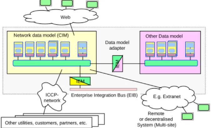
The "Network Operation" system node can be operated in a centralised or decentralised mode (multi-sites). It can communicate by means of loosely coupled interfaces with other system nodes (distributed intelligence). For performance reasons a closer coupling within an application
bundle is possible. Within a utility the system nodes can communicate by means of a gateway via a corporate bus (e.g. Enterprise Information Bus). Networking with the outside world (other utilities, customers, partners, etc.) is achieved by means of standard communications e.g. ICCP, Internet, etc. ICCP-network IEM IE M Web
Other utilities, customers, partners, etc.
Data model adapter
Remote or decentralised System (Multi-site)
Network data model (CIM) Other Data model
Enterprise Integration Bus (EIB) E.g. Extranet
Figure 2: Concept overview and architecture
The system node “Network Operation” represents a service provider to other users. This node and its applications can be embedded in a corporate IT world by means of interfaces. Application components are reusable. This will therefore allow an evolutionary adaptation to new needs.
Functional structuring (domains)
The system is built up by domains. This allows a flexible configuration and scaling depending on the application and business case.
Each domain is rather independent and is coupled by well defined interfaces. The hardware
resources can be configured for each domain depending on performance and availability requirements. Domain Object Model Engineering-System System- / Applications-Services Presentation Domain Application Domain Real-Time Domain
Communication Domain Internet/Intranet Process Inter Utility SCADA AutomationBasic
UI operation
Appl. A
e.g. Optim. Appl. Be.g. EMM
Appl. N UI Engineering
User
Externals
Figure 3: Domain model
Component architecture and data model The component architecture and common data model are the essential basis of a design concept which ensures future flexibility. layered system and standardised interfaces allows the
prerequisite for creating domains independent of each other.
A comprehensive domain Model models all data (process, system, communication, workflow, etc.) giving a unique user perspective in order to minimise system costs. Process objects are modelled on the base of CIM (Common Information Model IEC 61970).The component model as well as the component interface specification follow the rules of the "Plug & Play" approach in order to support performance optimisation and market differentiation.
Component Execution System and component adapter (e.g. Integration-Bus)
Based on IEC TC57 WG13 Status report Q4 1999
SCADA Network Legacy System Legacy Systems Adapter Interface Component Component interface Program Program CIM-Server Program Engineering-System Real-Time & Automation Database-Server Applications 1 - n ICCP-Network Communication IEM Other system nodes Internet/ Intranet Program Workflow Automation Public Data Public Data Public Data Public Data Public Data Program Public Data
Figure 4: Component architecture
Also the architecture facilitates the following features:
• efficient access the data of the system node
• programming by using Application Programming Interface (API)
• incremental upgrade of the system node with new applications
• product evolution without changes to existing interfaces
• embedding of legacy systems by means of wrappers
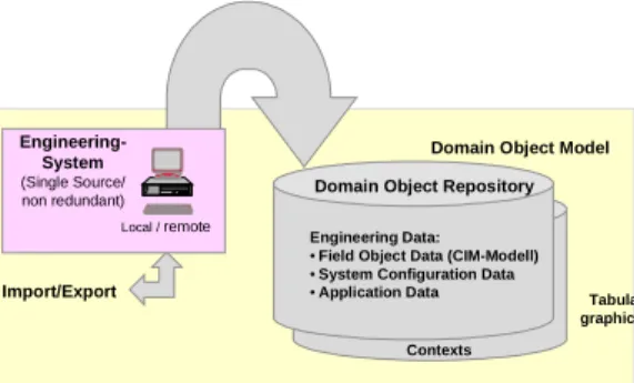
Engineering system (Application service) Essential parts of the total costs of ownership are data capture / maintenance, system configuring / maintenance, and adaptation to changing
business conditions. Special measures are taken in the Engineering system in order to minimise costs. These are:
• Engineering system is a source of all Engineering data
• object oriented efficient data entry for the whole system (single source / non redundant)
• Life cycle management (configuring, upgrades)
• CIM-compatible data storage
• data import / export via XML format
• data base with version management support
• Web-based user interface
Domain Object Repository Engineering Data: • Field Object Data (CIM-Modell) • System Configuration Data • Application Data
Tabular and graphical Data Domain Object Model
Contexts XML Import/Export Local / remote Engineering-System (Single Source/ non redundant)
Figure 5: Engineering system
Real-time processing (Application)
This domain is the proper real-time information provider (SCADA) for other applications in the corporate IT world. This domain is also providing the basis for automation and closed-loop control as automation functions are essential to allow increased operational efficiency in the liberalised market.
Communication (Application service) This domain contains the communication components to the outside world (process data, communication to other system nodes,
communication via Internet, mobile systems, etc.). The open concept of this domain meets the requirements of network oriented architecture. User Interface UI (Application service)
This component is the central and unifying part of all system components. It provides UI services for system integration. It is designed for Web
(browser) in order to have a unique operation concept. The browser is the source (container) of all UI components including scalable vector graphics and allows therefore an efficient integration of components from 3rd parties. Workflow (Application service)
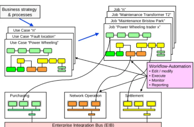
Each company has a multitude of various work flows. These work flows are based on business strategy / processes. Liberalisation and
deregulation are the driving forces for optimising business processes in order to reduce costs. The result of this optimisation is a set of Use Cases. These are used as a template workflow for real jobs. Workflow Automation tools allow the user to a) generate / modify Use Cases and jobs, b) execute and monitor jobs, and c) provide reporting for a quality assurance audit trail. Workflow Automation has to be applicable among one or several system nodes. The benefits of Workflow Automation are:
• Efficient workflow management (generation, modification, execution, monitoring,
reporting)
• Quality Assurance (no discrepancy between rules and the real working procedures) Nowadays Workflow Automation is well
established in document management systems. In the control centre environment there are some proprietary solutions implemented (for more information refer to the following appendix).
Purchasing Network Operation Settlement
Enterprise Integration Bus (EIB) Business strategy
& processes
Use Case “n” Use Case “Fault location” Use Case “Power Wheeling”
Job “n”
Job “Maintenance Transformer T2” Job “Maintenance Bristow Park” Job “Power Wheeling trader x”
Workflow-Automation • Edit / modify • Execute • Monitor • Reporting
Figure 6: Workflow overview
Summary and outlook
The concept presented suggests a solution to the challenge of the rapid changes in the electricity market. The essential benefits of the concept are:
• Minimising the total cost of ownership (including costs of complexity)
• Evolutionary adaptation of the system to new requirements
• Further use and reuse of existing field proven IT solutions
• Workflow and network oriented open
architecture based on international standards allowing "best of breed" choice of components and applications.
Improvements are expected in the areas of:
• Component standards (consolidation, expansion and widespread use)
• Implementation of measures to reduce complexity
• Spatial & vector oriented and open UI browsers
• Integration methods and tools for application integration within a company
• Workflow Automation based solutions.
---Appendix: "Example of Process reengineering & Workflow Automation
Workflow Automation has been implemented in the electrical distribution utility Bedzin in Poland. The following section highlights the applied
methodology of the implementation of Workflow Automation.
Background
Bedzin has a Distribution Management System (DMS) including SCADA. DMS has 7
decentralised regional control centres for the operation of the electrical distribution network. At night time and on weekends the network is centrally operated in one site. In addition to the classical SCADA features the following tasks had been identified:
• Planning & co-ordination of maintenance and inspection work
• Presentation and documentation of the network status (100kV - 0.4kV)
• Trouble Call and Fault Management
• Management of network resources Analysis
The analysis took into account the customers and inside the utility the departments Dispatching, Planning / Maintenance, Documentation,
Protection, Accounting / Settlement, Switchboard operator and Management. In phase 1 of the analysis a modular and extendible concept has been established which allows a stepwise integration of all departments concerned. The advantage of this approach was that the costs were easy to control and could easily be justified by showing the increasing benefits per step. In phase 2 the business processes were analysed. Result of the analysis
The result of the analysis was the optimisation and standardisation of workflow. This had been documented by the form of role model which is based on the assumption that each activity can be defined independent of organisation and people. In a next step Use Cases were established and graphically represented.
Implementation
Some but not all of the above mentioned concepts have been implemented in the project. The following section briefly describes the
implementation of WFA. Other implementation issues such as SCADA and distribution management functions are not described here below.
Data Model
The CIM data model has been taken as a base and adapted to the role model and business organisation. New dynamic objects such as
"Mobile Ground", "Bridge" and "Open Jumper" were added as well as so-called "Workflow" objects. It was the goal to support all known business processes as well as to be open for new - not yet known - business processes which will come with market liberalisation. The generic workflow model includes: Operator Authorisation, Job, Work procedures, planned steps (as
templates), Notification, Trouble Call, Fault registry.
The Workflow Automation documents all jobs, status of the electrical network as well as exchange of information in a well structured way for the voltage levels between 110 and 0.4 kV. This is the basis for work and cost analysis in order to improve workflow efficiency.
Workflow Tools
The Workflow Automation is an embedded application in the system node "Network
Operation". It gives the operator spatial views of e.g. erroneous network resources, network resources where work is in progress, location of the work crews, etc. In addition to the general tools the following tools were implemented:
• Trouble Call editor (entering of trouble calls, analysis of most likely outages)
• Failure Editor
• Workflow Support Editor (in order to support template workflow and adapt Jobs if required) Erroneous network resources or the location of working crews can be highlighted on network diagrams. The operation modes "Planning & Simulation" and "Execution" are supported. Operation
Definition
The workflow can be defined by the operator in a very efficient way by means of pre-specified templates (Use Cases). Templates are available for all known business processes related to the control room operator. Examples of available templates are: Maintenance on live or non-live network resources, Fault location, network restoration, etc. Templates can easily be adapted or created from scratch.
Test & Simulation
Each job can be tested and simulated and adapted, if necessary, before real execution. Execution and Monitoring
The Execution of a job goes step-by-step. Several jobs can be executed and monitored in parallel. A
quick overview of all on-going jobs is supported. Navigation between jobs and the related network object on the one-line diagram is supported. Experience in this project
The implemented WFA solution in the control centre system is successfully running and proven. The state-of-the-art data capture / maintenance system is a key factor of success. The delivered solution will be integrated in the corporate IT world.
The system has been designed in such a way that all known business processes are stored as templates. Templates can easily be adapted to changes in the business process as it is expected in the deregulated electricity market.
The concept for the integration of the system node "Network Operation" with other system nodes is currently being studied. The implemented system node supports a heterogeneous operating system environment such as Windows-NT, LINUX, UNIX, etc., and is therefore the enabling technology for integrating low cost operator workstations. Other applications such as "Energy Disposition", "Power Wheeling" can easily be integrated. An interface between Workflow Automation and electronic mail is provided.
The pace of expansion is decided by the utility. The decision is driven by the estimated saved cost potential
---List of references:
1 Kelly K, 1997, "Das Ende der Kontrolle: Die biologische Wende in Wirtschaft, Technik und Gesellschaft 2 Stüttgen M, 1999, "Strategien der
Komplexitätsbewältigung in Unternehmen
3 IEC 61970 and IEC 61968 standardisation (status 2000) 4 Schaub T & Tschudi M, 1999, Datenmanagement und
Abrechnung von Netzdurchleitungen, Siemens EV ME Glossary
API Application Programming Interface
CIM Common Information Model
CRM Customer Relation Management EIB Enterprise Integration Bus
EMM Energy Market Management
ICCP Inter Control Centre Communication Protocol IEC International Electrotechnical Commission IEM Information Exchange Model
IPP Independent Power Producer
IT Information Technology
OSI Open System Interconnect
WFA Workflow Automation