2012
WATER SAFETY PLAN
Managing
Drinking-Water Quality from
Catchment to
Consumer
Maynilad Water Safety Plan Revision No.1/November 2012
2
A collaboration work of the World Health Organization, Department of Health
Maynilad Water Safety Plan Revision No.1/November 2012
3
TABLE OF CONTENTS
TITLE Page Introduction 5 I. Maynilad WSP Team 8II Water Supply and Process Description 11
A. Water Sources 13
B. Water Treatment
B.1 La Mesa Water Treatment Plant No. 1&2 B.2 Putatan Water Treatment Plant
18
C. Ground Water 37
D Distribution 44
E. Process Flow Diagram Surface Water to Distribution
La Mesa Treatment Plant No 1&2 Putatan Water Treatment Ground Water
47 49 50
III Hazard Identification and Risk Assessment 51
IV Determine and Validate Control Measures, Reassessment and Prioritization of Risks
53
V VI
Improvement/Upgrade Plan
Monitoring of the Control Measures (Operational Monitoring)
53 54
VII Verification 54
VIII Management Procedures 55
IX Supporting Program 56
X Review and Audit 57
XI Revise WSP following an Incident 58
ANNEX I Hazard Identification and Risk Assessment A. Water Source: Surface
B. Water Treatment: La Mesa Water treatment Plant 1&2 C. Water Treatment: Putatan Water Treatment Plant D. Groundwater
59 61 65 69
Maynilad Water Safety Plan Revision No.1/November 2012
4
E. DistributionANNEX II Determine and Validate Control Measures, Reassessment and Prioritization of Risks
A. Water Source: Surface
B. Water Treatment: La Mesa Water treatment Plant 1&2 C. Water Treatment: Putatan Water Treatment Plant D. Groundwater
E. Distribution
ANNEX III Improvement/Upgrade Plan A. Water Source: Surface
B. Water Treatment: La Mesa Water treatment Plant 1&2 C. Water Treatment: Putatan Water Treatment Plant D. Groundwater
E. Distribution
ANNEX IV Monitoring of Control Measures (Operational Monitoring) A. Water Source: Surface
B. Water Treatment: La Mesa Water treatment Plant 1&2 C. Water Treatment: Putatan Water Treatment Plant D. Groundwater
E. Distribution ANNEX V Verification
A. Water Source: Surface
B. Water Treatment: La Mesa Water treatment Plant 1&2 C. Water Treatment: Putatan Water Treatment Plant D. Groundwater
E. Distribution ANNEX VI Supporting Programs
A. Water Source: Surface
B. Water Treatment: La Mesa Water treatment Plant 1&2 C. Water Treatment: Putatan Water Treatment Plant D. Groundwater
E. Distribution
ANNEX VII Sources of Water, Surface Water ANNEX VIII Gauging Points Threshold Limits
ANNEX IX Putatan Water Treatment Plant – Standard Operating Procedures ANNEX X Informative 70 73 76 87 96 98 102 103 106 113 114 116 118 135 141 142 144 144 146 148 149 150 151 152 153 154 156 157 188 203
Maynilad Water Safety Plan Revision No.1/November 2012
5
INTRODUCTION
Maynilad Water Services, Inc. (Maynilad) has long recognized the need for and the
importance of the formulation of Water Safety Plans (WSP) to its core business. Even before
the Department of Health (DOH) – the Philippine regulatory agency assigned for monitoring of
water quality – has mandated the formulation of WSP in 2007, Maynilad has already sought
assistance from the DOH and the World Health Organization (WHO) in the preparation of a
WSP for its business operations. In February 2006, Maynilad organized a multi-disciplinary
WSP team coming from its various operating units to assess and develop a model WSP for its
entire system. This WSP covers the water sources, conveyance system, water treatment,
pumps and reservoir, and the distribution network up to its customers. The task is tedious
and complicated since Maynilad does not manage the watershed that acts as the main source
of its water supply. Added to this is the fact that its operation covers surface and ground
water, three different water treatment plants, various facilities and a large and complicated
distribution system network traversing several different political boundaries.
The WSP intends to guarantee that safe drinking water is available to its customers at
all times through a sound water supply practice. This is achieved by 1) preventing the
contamination of the source of the raw water and provision of programs to immediatel y
resolve occurrences of contamination, 2) ensuring that the final quality of water delivered to
the consuming public are routinely monitored at a defined schedule and the water quality
results meet the established health-based standards set by the DOH and 3) preventing the
re-Maynilad Water Safety Plan Revision No.1/November 2012
6
contamination of its treated water during storage, distribution and handling until the water
reaches its customers. The WSP is described as a systematic procedure and comprehensive
plan formulated to 1) ensure that the desired water quality is met at all times at every stage of
all its operation, 2) identify parties who will be responsible to undertake the above tasks, 3)
predict events which may impair the quality of water and upset its operations 4) develop
programs that prevent the occurrence of such events and improve the system, 5) prepare
plans to manage the impacts of these events, 6) implement control and monitoring program
to assess effectiveness of the plan, 7) properly record and document the procedures and their
outcomes, 8) conduct regular review and audit of the WSP, 9) revise the plan following an
incident and 10) subject the plan to continual improvement.
The adoption of the WSP and the associated commitment of the company to the
approach translate to a number of benefits. The major benefits of developing and
implementing a water safety plan include the systematic and detailed assessment of its
processes and prioritization of hazards in all its operations and facilities, the establishment of
operational barriers to control hazardous events and the availability of conti ngency and
mitigating measures to cushion the impacts of these events. The WSP also provides an
organized and structured system to minimize the chances of failure of its services caused by
oversight, lapses on management or operational decisions and identifies parties responsible
for such. This process ensures the consistency of the quality of water supplied to Maynilad’s
customers and provides contingency plans to respond to system failures and unforeseeable
hazardous events and accidents, which may result in the impairment of its operations. On the
Maynilad Water Safety Plan Revision No.1/November 2012
7
overall, the advantages can be summarized as 1) compliance with water quality targets, 2)
application of best practices to secure water safety, 3) consistent water quality and safety, 4)
plans are in place to prevent crisis scenario from water quality impairment, 5) potential
savings from avoidance of incidents and accidents, 6) improvement in asset management and
7) ensure the satisfaction of customers.
The WSP covers the operations of La Mesa Treatment Plants No. 1 & 2 where the raw
water supply source comes from the Umiray-Angat-Ipo system, the newly constructed Putatan
Water Treatment Plant, which uses Laguna Lake as supply source, and the ground water
supply from small independent network.
Maynilad Water Safety Plan Revision No.1/November 2012
8
MAYNILAD WATER SAFETY PLAN TEAM STRUCTURE
FRANCISCO A. ARELLANOTeam Leader GREG R. ANTONIO Assistant Team Leader KRIS G. CATANGCATANG
Team Coordinator
CONSULTANTS WHO, DOH LLDA, NWRB DENR, LGU of Norzagaray
NCIP
DISTRIBUTION Rise Anne M. Xavier
Helen B. Labaro Mark Erwin H. Rodil
Ressie D. Vicente Josephus M. Dela Rosa
Alvin Ryan C. Ong Gian Carlo P. Reyes
Judith A. Dangue Roxanne C. Suganob WATER TREATMENT –
LMTP 1 & 2 Angelo Pablo J. Santos
Edgar P. Mati Ma. Ana E. Tria Juvelene C. Camposo
Jonalyn Madriaga Alexis Madison Y.
Datong Chester Y. Del Rosario
GROUND WATER Rodelio S. David Michael Joseph R. Buligan Jake N. Aradanas Freda P. Boleyley WATER TREATMENT- PWTP
Shiela Marie F. Afuang Benjamin C. Villa France Noelle B. Villaruel
Romer S. Jumawan Mark Vincent Q. Talosig
John Michael B. Perez Norbel L. Galeon WATER SOURCE -
SURFACE Salvador S. Leyble Herminigildo M. Medrano
London Philip L. Israel Marvin Villanueva Anna Liza P. Porciuncula
John Emmanuel B. Martinez
Maynilad Water Safety Plan Revision No.1/November 2012
9
MAYNILAD WATER SAFETY PLAN TEAM
Name Organization / Department Job Title Responsibility
Francisco A. Arellano CQESH SAVP, Corporate QESH Division WSP Team Leader Greg R. Antonio Water Production Head, Water Production
Department
WSP Asst. Team Leader
Kris G. Catangcatang QESH – IMS IMS Officer WSP Team Coordinator
Salvador S. Leyble Water Production-CPF Head, CPF Operations - Water source Herminigildo H. Medrano Water Production-CPF Officer, Ipo-Bicti Headworks Operations - Water source London Philip L. Israel Water Production-CPF PID Officer Operations - Water source Marvin Villanueva Water Production-CPF Headworks Controller 3, CPF Operations - Water source Anna Liza P. Porciuncula CQESH – IMS CQESH Officer Monitoring/Audit- Water source John Emmanuel B.
Martinez
CQESH – EMD CQESH Officer Monitoring/Audit- Water source
Angelo Pablo J. Santos La Mesa Water Treatment Plant Head, LMTP 1 LMTP-Water Treatment Operation Edgar P. Mati La Mesa Water Treatment Plant Officer-In-Charge, LMTP 2 LMTP-Water Treatment Operation Ma. Ana E. Tria La Mesa Water Treatment Plant Head, Planning and Support
Services
LMTP-Water Treatment Operation
Juvelene C. Camposo La Mesa Water Treatment Plant Chemical Officer LMTP-Water Treatment Process Laboratory Jonalyn Madriaga La Mesa Water Treatment Plant OIC, Process Control Officer LMTP-Water Treatment Process
Laboratory
Alexis Madison Y. Datong La Mesa Water Treatment Plant Maintenance Officer LMTP-Water Treatment Maintenance
Chester Y. Del Rosario CQESH – IMS CQESH Officer Monitoring/Audit- LMTP
Maynilad Water Safety Plan Revision No.1/November 2012
10
Benjamin C. Villa Putatan Water Treatment Plant Process Control Officer PWTP Operations
France Noelle B. Villaruel Putatan Water Treatment Plant Water Production Specialist PWTP - Chemical Monitoring Romer S. Jumawan Putatan Water Treatment Plant Shift Officer PWTP - Water Treatment Operation Mark Vincent Q. Talosig Putatan Water Treatment Plant Shift Officer PWTP - Water Treatment Operation John Michael B. Perez Putatan Water Treatment Plant Maintenance Officer PWTP - Maintenance Monitoring Norbel L. Galeon Putatan Water Treatment Plant Instrumentation Officer PWTP - Instrumentation Monitoring Rise Anne M. Javier CQESH – Central Laboratory Head, Analytical Section Water quality
Ressie D. Vicente Water Network Support Services Head Operations - Water Distribution Mark Erwin H. Rodil Water Network Central B / South Primary Head Operations - Water Distribution Josephus M. Dela Rosa Water Network South District BDOM Head Operations - Water Distribution Alvin Ryan C. Ong Water Network South District BDOM Engineer Operations - Water Distribution Helen B. Labaro CQESH – Central Laboratory Head, Surveillance Section Water quality surveillance Gian Carlo P. Reyes CQESH – Central Laboratory CQESH Officer, Analytical Water quality analysis Judith A. Dangue CQESH – Central Laboratory CQESH Analyst, Analytical Water quality analysis Roxanne C. Suganob CQESH – IMS CQESH Officer, IMS Surveillance
& Maintenance
Monitoring/Audit- Distribution Rodelio S. David Water Network Head (Central A BDO) Operations- Groundwater Michael Joseph R.
Buligan
Water Network Engineer (South BDO) Operations-Groundwater Jake N. Aradanas Water Network Engineer (South BDO) Operations - Groundwater
Maynilad Water Safety Plan Revision No.1/November 2012
11
II.
WATER SUPPLY and PROCESS DESCRIPTION
Maynilad is the private concessionaire that was awarded the exclusive right to take over
from the Metropolitan Waterworks and Sewerage System (MWSS), a government corporation,
the water supply and sewerage operations in the West Zone of Metro Manila. The West Zone
comprises 60% of the MWSS service population. This is a 25-year concession agreement, which
commenced on August 1, 1997 and will last up to July 31, 2022, and which has been extended
recently for another 15 years. The MWSS service area is divided into two operating zones: the
East Zone, managed by the Manila Water Company Inc. (MWCI) and the West Zone, which
Maynilad operates
(Figure 1)
.
The West Zone concession area
(Figure 2)
covers a total area of 540 km
2and consists of
ten cities and one municipality in Metro Manila as well as one city and five towns in Cavite
province. At the time of the privatization, there were only around 465,000 service connections
Maynilad Water Safety Plan Revision No.1/November 2012
12
in the West Zone. As of September 2012, Maynilad has installed a total of 1,734,225 water
service connections covering more than 8 million people
(Table 1)
.
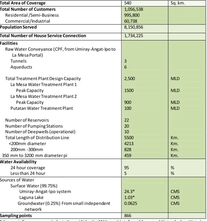
Table 1. Basic Information on Maynilad Water (as of September 2012)
Total Area of Coverage 540 Sq. km.
Total Number of Customers
Residential /Semi-Business Commercial/Industrial 1,056,538 995,800 60,738 Population Served 8,150,856
Total Number of House Service Connection 1,734,225
Facilities
Raw Water Conveyance (CPF, from Umiray-Angat-Ipo to La Mesa Portal)
Tunnels Aqueducts
Total Treatment Plant Design Capacity La Mesa Water Treatment Plant 1 Peak Capacity
La Mesa Water Treatment Plant 2 Peak Capacity
Putatan Water Treatment Plant Number of Reservoirs
Number of Pumping Stations Number of Deepwells (operational) Total Length of Distribution Line
<200mm diameter 200mm -300mm 350 mm to 3200 mm diameter pi 3 6 2,500 1500 900 100 22 20 10 5500 4213 828 459 MLD MLD MLD MLD Km. Km. Km. Km. Water Availability 24 hour coverage Less than 24 hour
95 5 % % Sources of Water Surface Water (99.75%) Umiray-Angat-Ipo system Laguna Lake
Groundwater (0.25%) From small independent network 24.3* 1.03* 0.0625 CMS CMS CMS Sampling points 866
Maynilad Water Safety Plan Revision No.1/November 2012
13
A.
Water Sources
With the rapid increase in population of Metro Manila, the need for water supply
has greatly increased as well. The metro draws 96.76% of its raw water supply from the
Umiray-Angat-Ipo system in Norzagaray, Bulacan, and this has been the only source for decades. The
heart of the system is the Angat Dam, which is a multi-purpose dam and is intended for power,
irrigation and water supply. MWSS gets 4,000 MLD of water supply source from this facility and
60% of this is allocated to Maynilad. The Department of Environment and Natural Resources
(DENR) handles the maintenance of the Umiray watershed while the National Power
Corporation (NPC), the power generating company, maintains the Angat watershed and the
DENR, MWSS and the two concessionaires’, MWSI and MWCI, maintain the Ipo watershed. The
remaining 3.99% of raw water supply is sourced from the Laguna Lake and 0.25% is sourced
from deep wells.
The country’s water resources has a land area of 300,000 sq.km., an annual rainfall
of 2,400 mm run off collected from rainfall of 1,000 to 2000 mm and an estimated aggregate
area for groundwater reservoir of 50,000 sq.km. The surface water dependable water supply
with 80% probability is 125.79 MCM. However, only 80% of the Philippine population has
access to safe potable water.
Maynilad, as the concessionaire for the West Zone of greater Metro Manila,
recognized the increasing current and future water supply requirements and therefore sought
to develop an alternate water source to help cater to the customers, specifically in Muntinlupa,
Las Pinas and Cavite. The Laguna Lake was identified in 2009 as an alternate water source to
Angat Dam. And in 2010, a state-of the-art treatment plant was built in Barangay Putatan,
Muntinlupa, to make sure that water drawn from the lake is fit for domestic consumption.
Maynilad Water Safety Plan Revision No.1/November 2012
14
Laguna Lake (Laguna de Bay) is the largest lake in the Philippines located east of
Metro Manila between the provinces of Laguna to the south and Rizal to the north. The
freshwater lake has a surface area of about 911 km
2(352 sq. mi), with an average depth of
about 2.8 meters (9 ft. 2 in) and an elevation of about 1 meter (3 ft. 3 in) above sea level. In
order to reduce the flooding in Manila along the Pasig River, during heavy rains, the peak water
flows of the Marikina River are diverted via the Manggahan Floodway to Laguna de Bay, which
serves as a temporary reservoir. In case the water level on the lake is higher than the Marikina
River, the flow on the floodway is reversed. In normal circumstances, both Marikina River and
the lake drain through Pasig River to Manila Bay.
The lake has been used as a navigation lane for passenger boats since the Spanish
colonial era. It is also used as a source of water for the Kalayaan Pumped Storage Power Plant in
Kalayaan, Laguna. Other uses of the lake includes fishery, aquaculture, recreation, food support
for the growing duck industry, irrigation and a "virtual" cistern for domestic, agricultural and
industrial effluents. Because of its importance in the development of the Laguna de Bay Region,
unlike other lakes in the country, its water quality and general condition are closely monitored.
At present, this important water resource has been greatly affected by development pressures
like population growth, rapid industrialization, and resources allocation.
The Angat multi-purpose dam located in Norzagaray, Bulacan has a capacity of 850
MCM with an operating level of 181 – 214M and a low level outlet at 101M. Angat watershed
area, which is in the Northern tip of the Sierra Madre Mountain ranges, has an area of about
62,000 hectares. An additional 9 cu m / sec from the Umiray trans-basin tunnel flows to Angat
daily from the Umiray River.
The watershed areas of Angat Dam and the Umiray River are under attack by intruders
and illegal loggers and their activities have resulted to mudslides and flash floods during storms
and heavy rainfall. The result of the abuse especially in the watershed of Umiray River has been
very costly. Aside from the problems for the treatment plants because of the very high
Maynilad Water Safety Plan Revision No.1/November 2012
15
incoming raw water turbidity exceeding 1000 NTU and Manganese that is dissolved by the
raging floodwaters from the natural geological formation, lives were lost a nd properties were
destroyed. The activities of the Dumagat, an indigenous tribe who lives primitively in the
watershed are another source of some organic and biological pollutants of the water sources.
Water from the Angat Dam flows to the Ipo Dam through the auxiliary turbines 1, 2, 3, 4
& 5 and terminating at the La Mesa Treatment Plants
(Figure 3)
. Angat Dam releases 41 CMS
daily from its five auxiliary turbines to Ipo Dam, which is no longer an impounding dam but a
diversionary dam. From Ipo Dam the water flows and is diverted to a series of tunnels and
aqueducts conveyance system of about 24 kms. terminating at the La Mesa portal where it is
shared by Maynilad Water’s La Mesa Treatment Plants and Manila Water’s La Mesa Reservoir /
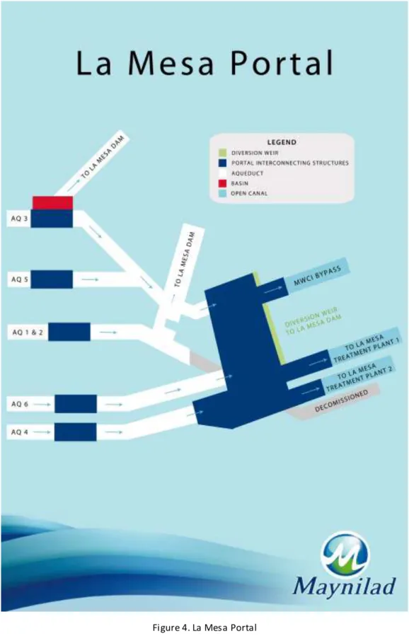
Balara aqueducts on a 60 – 40 % split as per Concession Agreement
(Figure 4)
.
Maynilad Water Safety Plan Revision No.1/November 2012
16
Fi gure 3. Hea dworks a nd Conveya nceMaynilad Water Safety Plan Revision No.1/November 2012
17
Maynilad Water Safety Plan Revision No.1/November 2012
18
B.
Water Treatment
Maynilad operates three (3) treatment plants for water production: La Mesa Water
Treatment Plant Nos. 1 and 2 (LMTP 1 and LMTP 2) located in Quezon City and the Putatan
Water Treatment Plant in Muntinlupa.
LMTP 1 uses the standard conventional coagulation-flocculation-sedimentation, rapid
gravity dual-media filtration and chlorine gas disinfection. It has no automation and minimal
rehabilitation since its construction. It has very minimal electro-mechanical equipment and
relies mostly on hydraulic properties of water to backwash its filters and on gravity to convey
raw water from the source, into the plant and out into the distribution system. LMTP 2 also
uses coagulation-flocculation process but employs the pulsator clarifier for turbidity removal. It
undergoes single-media filtration and final disinfection by chlorination. Both systems have
capability for preliminary and post-chlorination. It uses alum for the coagulation and is aided by
polymers to enhance floc formation as pH is adjusted during coagulation, if necessary, using
caustic soda.
Putatan Water Treatment Plant is the newly constructed state-of-the-art water
treatment plant in Muntinlupa to serve thousands of households in the city. The plant use
microfiltration and reverse osmosis to treat raw water from Laguna Lake. The plant has been
equipped with 14 units of microfiltration and six units of reverse osmosis assemblies.
The groundwater undergoes only disinfection, either through liquid chlorine or
hypochlorite solution.
B.1
La Mesa Water Treatment Plants 1 & 2
Both LMTP 1 and LMTP 2 plants are located in the La Mesa Dam compound and are ISO
9001:2008, ISO 1400:2004 and OSHAS 1800 Integrated Management System certified. This is
Maynilad Water Safety Plan Revision No.1/November 2012
19
the proof of Maynilad’s commitment to the quality of its product, protection of the
environment, safety and health of its employees and satisfaction of its customers. The two
plants were officially conferred by TUV: SUD, Philippines on October 18, 2006 with an
Integrated Management System certified. Proudly, Maynilad became the first water utility firm
in the Philippines to have this distinction. As Maynilad continues to operate, it stays focus and
guided by its Quality, Environment, Safety and Health policy and objectives.
The water enters both treatment plants after traveling over 24 kilometers through
tunnels and aqueducts from the Angat-Ipo-Bicti source network. Water passes through screens
that prevent entry of foreign objects such as grass, leaves, tree limbs and other large floatables,
thus protecting our rapid mixers, flocculators, regulated valves and flow meter sensors from
damage.
La Mesa Treatment Plant No. 1, located in Novaliches, Quezon City is Asia’s largest plant
and fourth in the world, started operating in 1982 and was completed in 1983. It was designed
by Camp, Dresser and Mckeey with a capacity of 1500 MLD and peak output of 1650 MLD and is
fully operational for almost 30 years now. This PHP 250 million plant is a low-cost technological
package that features an energy efficient design. It is standard conventional coagulation –
flocculation – sedimentation - rapid gravity filter-disinfection plant with no automation and
minimal rehabilitation since its construction. It has very minimal electro mechanical equipment
and relies mostly on hydraulic properties of water to backwash its filters and on gravity to
convey raw water from the source, into the plant and out into the distribution system.
Caustic soda is first applied as delivered in 50% concentration before the water enters
the radial gates of LMTP 1. However, this is only conducted if there is a need for pH and/or
alkalinity correction at the start
(Figure 6a and 6b)
. Hydrated or quick Lime is used as an
alternate to caustic soda and prepared in a 2-3% concentration solution. In the coagulation
process, rapid mixers uniformly disperse aluminum sulfate (in 50% concentration with 8 to 8.5%
alumina content) throughout the raw water. After rapid mixing, the water enters the three
Maynilad Water Safety Plan Revision No.1/November 2012
20
stages flocculation chambers where polymer, as coagulant aid, is added in the first stage.
Polymers could be cationic, anionic or non-ionic whichever is best suited for the quality of
incoming raw water. It is prepared in different concentrations depending on the raw water
turbidity being treated. Chlorine may also be added for pre-treatment disinfection where
dosage depends on the demand. The 36 flocculators in each half of the plant is where water is
gently agitated causing the small clusters of suspended solids to collide with and stick to each
other and form into larger particles called ‘floc’. The water then enters 12 sedimentation
basins where the flocs are settled out by gravity. Intermediate chlorination can be applied in
this process depending on the need. It then proceeds to the filtration process through the 24
filter units in the plant. In order to optimize the operation of the filter units, backwashing is
conducted to remove the collected flocs with the backwashed water being sent to four lagoons
for recovery or recycling back into the plant. Finally, the product water undergoes
post-chlorination (residual chlorine of 1.0 to 1.5 ppm) before being sent out to the distribution
system.
The La Mesa Treatment Plant No. 2 was designed and constructed under the Angat
Water Supply Optimization Project (AWSOP) to supply water to the Northern part of Metro
Manila (included in the West Service Zone as per Concession Agreement) and was
commissioned in 1995. Designed by Degremont of France, it uses coagulation, flocculation,
pulsator-clarifier, filtration, disinfection process having a design capacity of 900 million liters
per day during maximum flow, with an allowable overload of 10 % and can produce as high as
990 MLD.
The raw water passes through the bar screens to remove large objects such as rags,
plastics bottles, and other floatables from entering the treatment plant
(Figure 7a and 7b)
.
Screened water then enters two repartition chambers where four flash mixers (2 for each
repartition) uniformly disperse into the water various treatment chemicals as per the following
injection order:
Maynilad Water Safety Plan Revision No.1/November 2012
21
1.
Caustic soda is applied as delivered at 50% concentration if required for pH and/or
alkalinity correction/neutralization; hydrated or quick lime can be used as an
alternative and prepared in 2-3% concentration solution.
2.
Chorine for pre-treatment disinfection.
3.
Primary coagulant - Aluminum Sulfate which is applied as delivered at 50%
concentration with 8.00 to 8.50% alumina content
4.
Polymer, as coagulation aid, that could be cationic, anionic or non-ionic, whichever
is suited, is prepared in concentrations dependent on raw water quality.
In coagulation, fine colloidal suspended solids are gathered into bulky and heavy flocs by
introducing aluminum sulfate into the raw water. The addition of polymer in the flocculation
step hastens the cohesion and relatively increases the volume of the flocs formed. The water
then flows into eight pulsator-clarifiers where the flocs are allowed to settle at the clarifier
basins, which is regularly extracted by means of sludge draw-off valves. The pulsation increases
the time of contact between the water and the sludge - forming blankets thereby, improving
water quality. The blanket also serves as a pre-filter to the clarified water. The clarified water
then undergoes filtration through twenty (20) filter beds. These filters complete the treatment
process by removal of the flocs, which escaped or had passed through the sludge blanket in the
clarifiers. Backwashing is also applied in the filters with the resulting backwash water stored in
the recovery tank and is continuously recovered to combine with the incoming raw water for
another cycle of treatment. The water coming from the filter then undergoes post-chlorination
(residual chlorine of 1.0 to 1.5 ppm) before leaving the plant for distribution.
Other chemical used when beset with high Manganese content is Potassium
Permanganate.
Both plants have pre-chlorination and post-chlorination (LMTP 1 has an additional
intermediate chlorination provision) to handle high levels of algae and ensure the presence of
required residual chlorine of the finished water up to the farthest end of the distribution
Maynilad Water Safety Plan Revision No.1/November 2012
22
system. Maynilad uses liquid-gas chlorine in its operation and there are no plans to shift to new
disinfection systems in the near future. The use of chlorine has always been effective in treating
the bacteriological and biological agents in water. Chlorine dosage is always within the safe and
prescribed limits to meet the requirements set by the Philippine National Standards for
Drinking Water 2007 and by the MWSI Water Production Quality Plan. Seeing the importance of
chlorination in the treatment of water, sufficient measures are also in place should there be any
failures in the chlorination facilities.
During the dry season, manganese present in the low water levels in Angat Dam can
enter with the raw water to the treatment plants. To address this, there is a stand-by potassium
permanganate treatment unit to precipitate the dissolved manganese and remove it before it
enters the pre-chlorination.
All of the LMTP 1 finished water is sent to Bagbag Reservoir via the 3.2M diameter main
transport pipe while part of LMTP 2 finished water is sent to the 50-ML La Mesa Reservoir and
pumped to the northern distribution system and the other part goes to Bagbag Reservoir in
Novaliches to supply the Central and Southern portion of the service area by gravity.
In the last 6 years, the average monthly output for LMTP 1 & 2 have been 94% and 91%
of their design capacities, respectively, except for the abnormal periods of operation,
specifically when a prolonged period of El Nino was experienced in 1998 which resulted in the
high Manganese content of the raw water. There were also incidents when prolonged rainy
season in Southern Luzon resulted in highly turbid raw water, such as during late November
2004 to January 2005, November 2007, September 2009 and August 2012, that was beyond the
capacity of the treatment plants. It has been learned from these episodes that it is advisable to
choose lower output of good quality than higher output of compromised quality.
Maynilad Water Safety Plan Revision No.1/November 2012
23
Figure 6a. Schematic Diagram - La Mesa Treatment Plant 1, Water Treatment Process
La Mesa Treatment Plant 1
Water Treatment Process
PSS – Updated AO July 27,
2012
Maynilad Water Safety Plan Revision No.1/November 2012
24
Figure 6b. Block Diagram - La Mesa Treatment Plant No 1, Water Treatment Process
LA MESA TREATMENT PLANT No. 1
WATER TREATMENT PROCESS
BLOCK DIAGRAM
Junction
Box
Structure
Coagulation
Sedimentation
Filtration
Recovery
Lagoon
Raw water
from
LMTP-1
Open canal
(Portal)
Caustic
Soda
Potassium
Permanganate
Aluminum
Sulfate
Pre-chlorination
Polymer
Losses due to leakages of
24 Butterfly valves
(3.3 mld or 137 cu.m./hr.)
Intermediate Chlorination
Post Chlorination
To Bagbag
Reservoir
Losses due to:
a. Backwashing (2340 cu.m./bed/12 min.)
b. Filter Drain Sluice Gate leakage (negligible)
c. Unfiltered Water (900cu.m./basin) - to be drained
before backwash
Maynilad Water Safety Plan Revision No.1/November 2012
25
Figure 7a. Schematic Diagram- La Mesa Treatment Plant 2, Water Treatment Process
La Mesa Treatment Plant 2
Water Treatment Process
PSS – Updated AO July 27,
2012
Maynilad Water Safety Plan Revision No.1/November 2012
26
Figure 7b. Block Diagram - La Mesa Treatment Plant No 2, Water Treatment Process
LA MESA TREATMENT PLANT No. 2
WATER TREATMENT PROCESS
BLOCK DIAGRAM
Flocculation
(Pulsator-
Clarifier)
Coagulation
(Repartition
Building
)
Filtration
Washwater
Recovery
Tank
Raw water from
LMTP-2 Open
canal (Portal)
Post Chlorination
Losses due Backwashing:
a. 300 cu.m. / filter bed / 14 min.
b. 1.90 mld from leaks
Screening
(Raw Water
Inlet)
Pre- chlorination
Caustic Soda
Aluminum Sulfate
Polymer
Recovered Water
Caustic Soda
(if necessary)
Effluent
Proposed Potassium
Permanganate Application
(300 m. away from the plant)
Maynilad Water Safety Plan Revision No.1/November 2012
27
B.2
Putatan Water Treatment Plant
The newly constructed 100-mld Putatan Water Treatment Plant is located in the city of
Muntinlupa, situated 22km south of Metro Manila
(Figure 8)
. The plant is the first water
treatment facility that taps into Laguna Lake as an alternative water source to Angat Dam in
Bulacan. Laguna Lake is the largest lake in the Philippines and the third-largest freshwater lake
in South East Asia. It is also the first significant bulk water supply source for the Greater Manila.
The Putatan Water Treatment Plant Phase 1 (100 MLD) is part of Maynilad capital
expansion program and is supplying the potable water requirement of the cities of Muntinlupa,
Las Pinas, Paranaque and ultimately Cavite City & the municipalities of Rosario, Imus, Noveleta,
Bacoor and Kawit (when Phase 2 -- of 200 MLD capacity -- is completed).
To ensure that water drawn from Laguna Lake is fit for drinking, an advanced process of
microfiltration and reverse osmosis has been adopted to purify the water. The plant has been
fabricated with four (4) Diffused Air Flotation (DAF) trains, five (5) Amiad Strainers, fourteen
(14) units of Microfiltration and six (6) units of Reverse Osmosis (RO) trains, sludge dewatering
system, gas chlorination system and product pumping system
(Figure 9)
. The design
specifications of the plant are also in compliance with the requirements by the Department of
Health (DOH), Philippine National Standards for Drinking Water (PNSDW).
Maynilad Water Safety Plan Revision No.1/November 2012
28
Figure 8.Location of Putatan Water Treatment Plant
Maynilad Water Safety Plan Revision No.1/November 2012
29
Figure 9. Putatan Water Treatment Plant ProcessLAKE INTAKE FOREBAY (Raw Water)
(DAF) DISSOLVED AIR FLOTATION
MICROFILTRATION
REVERSE OSMOSIS
RESERVOIR
Three vertical turbine pumps Raw water pump (132 KW, 880 rpm)
40 hp Twister - Mixers (8 units) (60 hz – 0.43KW; 50 hz-0.37KW) - Skimmers (4 units) - Scrappers (4 units) (50 hp at 3540 rpm)
- MF Feed pumps (6 units (5+1)) (215 hp at 1790 rpm)
- 5 units Amiad Strainer (500um) max flow rate – 1200m3/hr
-Hollow Fiber Membrane (0.1um) -14 racks (68 modules per rack) -952 modules
- Six identical RO trains (5.6 mld of permeate
flow per train)
-Chamber 1 (6.6 mld) -Chamber 2 (7.4 mld)
AYALA ALABANG GEN DISTRIBUTION
-Booster pumps (3 units (2+1) ( 200 KW at 1789 rpm)
- Booster pumps (3 units (2+1)) (480KW at 1789 rpm)
PRETREATED WATER TANK
PERMEATE TANK Brine Solution
(To Lake)
DECANTER
sludge
PUTATAN MFRO TREATMENT PLANT Revised
ACH application
Chlorination KMnO4 Application
AMIAD Strainer MF Feed Pumps
Raw Water Pumps
Sump Pit -Backwash Water For Flushing /CIP Chemicals : RO Treat 100, SMBS
For EFM Chemicals : Citric Acid, Sodium Hydroxide,
Sodium Hypochlorite Chemicals :
Maynilad Water Safety Plan Revision No.1/November 2012
30
Intake and Forebay (Drawing of Raw Water and Aeration)
Water is drawn from the Laguna Lake via two channels. The water flows from the Lake
into the plant to a temporary storage basin called the Forebay, where a 40-hp Twister aerator is
operated. Aeration is the process of dissolving air in water to increase the amount of oxygen
dissolved in it, which generally improves the quality of the water.
Intake
Forebay
Parabolic screen was installed to
prevent plastics and other trash
from entering the system
Transition pit screen
•
Raw water basin
•
Aeration process takes place
•
Abstraction point of raw
Maynilad Water Safety Plan Revision No.1/November 2012
31
Raw Water System
From the Forebay, water is drawn into the pre-treatment stage by means of three
vertical turbine pumps. As the raw water enters the Dissolved Air Flotation chambers, the
primary coagulant, Aluminum Chlorohydrate (ACH) is injected. The coagulant is primarily
responsible for the formation of sludge, which is generally the collection of unwanted
substances removed from the raw water.
Dissolved Air Flotation
Dissolved Air Flotation (DAF) is a process wherein sludge removal is achieved by
dissolving air in the water under pressure in a saturator and then releasing the air at normal
pressure in a flotation tank. The released air forms tiny bubbles, which adhere to the
suspended flocs causing them to float to the surface of the water where they may then be
removed by a skimming device.
As the raw water injected with ACH is mixed by means of slow and flash mixers, flocs are
formed. These flocs float to the surface of the DAF tank where they are removed by mechanical
surface and bottom scrapers into the sludge trough and pumped to the sludge lagoon or
decanter centrifuge (sludge-dewatering device).
The clarified water coming from the DAF tanks flows to the Pre-Treated Tanks before
entering the Microfiltration system.
Maynilad Water Safety Plan Revision No.1/November 2012
32
Raw Water Pumps
Pre-Treated Tank
The pre-treatment process is primarily for the removal or reduction of:
• Color
• Iron
• Manganese
• Heavy metals
• Taste and odor
• Algae
• High-level Turbidity
Maynilad Water Safety Plan Revision No.1/November 2012
33
Microfiltration and Reverse Osmosis (MF-RO)
From the pre-treated tanks, Microfiltration (MF) feed pumps, 6 units with 1 unit as
stand-by, pump water into the MF system. The water passes through five 500-micron filter
strainers before finally entering the micro filters.
Microfiltration (0.1 to 1.0 Am) is ideal for removing suspended particles, bacteria, and
many viruses from water. Microfiltration membranes normally operate at pressures of between
0 to 6.9 bars. It is a means of trapping and removing such contaminants as Giardia cysts (8-30
Am), Cryptosporidium cells (3-8 Am), and other bacteria ranging from 0.2 to 50 Am by means of
a porous barrier that is fixed in place. In microfiltration, such impurities are simply too large to
pass through. To put the size of these particles in perspective, the diameter of a human hair is
in the range of 20 to 120 Am. Membrane treatment performance is relatively insensitive to
rapid changes in the feed water composition unlike systems based on chemical addition and
coagulation. Membrane technology is accepted throughout the world as an effective and
economical water treatment method.
The plant has 14 MF module racks (shown below as the vertical ecru tubes ), which
operate simultaneously. Here, most of the particles are removed to produce clear water that
Maynilad Water Safety Plan Revision No.1/November 2012
34
can already be potable after chlorination. This filtered water is often referred to as the MF
filtrate.
Reverse Osmosis
Reverse Osmosis (RO) requires pressure to drive water through a synthetic membrane
to separate the water from the constituents that are dissolved in it. The RO process involves
water and dissolved “salts” diffusing through a semi-permeable membrane. The passage of the
water through the RO membrane occurs at a much faster rate than of the salts. The portion of
the water not passing through the membrane i.e., rejected by the membrane retains most of
the salts and becomes concentrated, thus the name concentrate, brine, or reject. In addition to
rejecting salts, minerals and other inorganic compounds, the RO membrane is also capable of
rejecting most of the organic compounds, such as pesticides , herbicides, color, total organic
carbon (TOC), and disinfection by-products (DBP) precursors that are present in the feed water.
Another benefit of RO membranes is their ability to stop the passage of microorganisms from
the feed side to the permeate side of the membrane. The primary goal of the RO system is the
reduction of Total Dissolved Solids (TDS) during periods of TDS spikes and the lowering of
Disinfection By-Product (DBP) Precursors, Tri-Halo Methane (THM) and Halo Acetic Acid (HAA)
precursors, in order for the blended product water to comply and/or exceeds the PNSDW
guidelines. The RO system is also designed to reduce or remove other unwanted constituents
that are present in the raw water, such as:
Maynilad Water Safety Plan Revision No.1/November 2012
35
• Iron
• Total Organic Carbon (TOC) and Color
• High Hardness
• Excessive Alkalinity
• Total Dissolved Solids (TDS)
• Ammonia (Laguna Lake has occasional ammonia “spikes”)
Currently for the plant, whenever the TDS reaches 400 ppm, RO units are operated to
exceed the PNSDW standard (equal to or less than 500ppm) (The design blend ratio is 34% RO
permeate and 66% MF filtrate when feed TDS is 700 ppm. Depending on the Feed TDS from
<500 up to 2,800 ppm, any number of RO can be put into operation to maintain blended
product water quality that meets or exceeds the PNSDW standards. The hydraulic design
capacity of the plant is 100 MLD (34 MLD RO, 66 MLD MF Filtrate). The design blend ratio is a
function of the feed water quality and the desired final product water quality data.)
Maynilad Water Safety Plan Revision No.1/November 2012
36
Chlorination, Storage and Distribution
After the MF-RO process, the water is chlorinated for disinfection purposes. Currently
the plant uses powder chlorine (calcium hypochlorite) and gas chlorine for this phase. There is
the option of injecting chlorine before (pre-chlorination) the water enters the 14 ML reservoir
where it is temporarily stored before pumping to Ayala Alabang Village and the general
distribution lines. Post-chlorination is also being done to ensure that the PNSDW residual
chlorine requirement for the product water is met. There are presently 6 product water booster
pumps available for distribution. Three of these are for Ayala Alabang, and the other three
high-pressure pumps are for general distribution.
Maynilad Water Safety Plan Revision No.1/November 2012
37
C.
GROUND WATER
The existing deep well facilities in the West Zone include 10 deep well stations, network
of pipelines, elevated water tanks and reservoirs. With the current deep well facilities of West
Zone, it serves the following areas: parts of Valenzuela, Malabon, Quezon City in the North and
parts of Muntinlupa and Cavite in the South.
At present the ten operational deep well pumping stations are: 1.Dona Juana in
Malabon, 2.Brittany in Quezon City, 3.Bagong Silang Phase 10 in Caloocan City, 4.Ayala South
Vale Deepwell 3 in Ayala South Vale, Gawaran, Bacoor, Cavite, 5.Ayala South Vale Deepwell 4 in
St Jude Subd, Bacoor, Cavite, 6.Georosville in Pagasa, Imus, 7.Malagasang 2-D in Imus, 8.Molino
in Bacoor, 9.Pandawan in Rosario, Cavite and 10.Poblacion, Noveleta, Rosario.
The deep well facilities will augment water pressure in the high portions and far end of
the pipelines of the service areas.
The functions of the Deep Well Pumping Plants Operation of Water Network are the
following:
Operates all deep well pumping stations in accordance with approved operating
schedules
Performs preventive maintenance activities to all deep well pumping stations,
equipment and vehicles of the unit
Performs minor repair and maintenance works to all pumping station’s
electro-mechanical equipment and machineries and electro-mechanical equipment used by the unit
Observe and record operating conditions of all pumping stations
Recommends / initiates improvement / rehabilitations of pumping stations, equipment
and vehicles
Maynilad Water Safety Plan Revision No.1/November 2012
38
The water quality of the groundwater is compatible with the PNSDW and thus, do not
require any treatment except for preventive disinfection using Calcium Hypochlorite (HTH). The
dosage is 3 kg HTH to 100 liters of water where the chlorine concentration is regulated by the
chemical feeder. The water sample taken from the distribution line 100 meters away from the
well source should have a minimum 0.30-ppm of residual chlorine. Based on this field testing,
low residual chlorine will increase the chemical feed rate or high residual chlorine will reduce
the chemical feed rate.
If the groundwater source is contaminated, shock chlorination is initiated. Twenty (20)
kg of Calcium Hypochlorite (HTH) granules is thoroughly mixed to 100 liters of clean water. The
chlorine mixture is poured into the sounding tube of the well and is allowed to stay for 24
hours. After 24 hours, well water is pumped out and the water is tested for microbial analysis.
Typically, an MWSS/MWSI well is dug with a depth of 305 meters (1000 ft.). The natural
groundwater aquifer in the franchise area is found in two geological formations occurring at
100-120 m (328-390 ft.) and at 167 m (550 ft.) and below. So as not to compete with the
groundwater source of the Artesian/Shallow wells of locals (e.g. farmers, residence, etc.), wells
start their perforated casing from 600 ft. and below. This also assures that only the
groundwater occurring in the lower but true natural aquifer is abstracted. Refer to “Study for
the Groundwater Development in Metro Manila (SGDMM), June 1992, Volume 1, JICA Report”
(a copy of which is in the possession of the unit in charge of the Deep wells of the Water
Network Department).
The geological formation of the franchise area of Maynilad is formed mainly by the
Guadalupe formation and is underlain by alluvium in the coastal areas. The Guadalupe
Formation forms the good aquifer, which represents the recharge in the franchise area and is
part of the Luzon Central Valley Basin.
Maynilad Water Safety Plan Revision No.1/November 2012
39
The southern part of the franchise area, particularly the Muntinlupa Area is prone to
land subsidence due mainly to the Marikina Fault Line. This fault line has caused severa l well
casings of the deep well to slip off-center thus causing intrusion to the well. Fortunately, in
other parts of the franchise area, the Guadalupe Formation is consolidated and the Alluvium
clayey bed is thin therefore, the probability of land subsidence occurring in these areas is nil.
Fluoride, especially in the coastal franchise areas , Cavite area, is relatively high. Since
fluoride occurs naturally in groundwater, it is very difficult to prevent or eradicate. Part of the
short-term solution is to dilute the groundwater with surface water and the long
term/permanent solution is to bring the surface water to these groundwater-supplied areas.
Direct recharge from rainfall was estimated based on the following equation:
P=R+E+I
where:
P = mean annual rainfall
R = run off
E = evapotranspiration
I = effective infiltration (all in millimeters)
Based on the same 1992 JICA study mentioned above, values are as follows:
Annual Rainfall = 2, 329.7
Run off = 1, 397.8
Evapotranspiration = 816.6
Recharge = 115.3 (4.9% of annual rainfall)
Fortunately for the franchise area of MWSI, the deep wells in the inclusive zone have
relatively low risk of contamination by pollutants since the area is protected by prehistoric
sedimentary basin. The Southwest Luzon Upland is situated south of the MWSI franchise area.
The elevation decreases towards the north. The southern piedmont area of Taal Volcano is
contiguous to Manila Bay and Laguna de Bay and is widely covered by thick volcanic materials
Maynilad Water Safety Plan Revision No.1/November 2012
40
and mud flows. The area constitutes a recharge zone of the lake water of the Laguna de Bay
and of the groundwater south of the franchise areas.
Deep well stations operated by Maynilad as of October 2012 including their addresses,
operating schedules, capacities and the influence areas under the Booster and Deep well
Operation and Maintenance of the Water Network Department are listed in
Table 2
.
Maynilad Water Safety Plan Revision No.1/November 2012
41
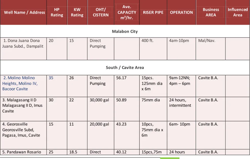
Table 2. LIST OF MAYNILAD OPERATIONAL DEEP WELL STATIONS
Well Name / Address
HP
Rating
KW
Rating
OHT/
CISTERN
Ave.
CAPACITY
m³/hr.
RISER PIPE
OPERATION
Business
AREA
Influenced
Area
Malabon City
1. Dona Juana Dona
Juana Subd., Dampalit
20
15
Direct
Pumping
400 ft.
4am-10pm
Mal/Nav.
South / Cavite Area
2. Molino Molino
Heights, Molino IV,
Bacoor Cavite
35
26
Direct
Pumping
56.17
15pcs.
125mm dia
x 6m
9am-12NN;
4pm – 6pm
Cavite B.A.
3. Malagasang II D
Malagasang II D, Imus
Cavite
30
22
30,000 gal
50.89
75mm dia
24 hours,
intermittent
Cavite B.A.
4. Georosville
Georosville Subd,
Pagasa, Imus, Cavite
15
11
20,000 gal
43.23
10pcs,
75mm dia x
6m
6am- 10pm
Cavite B.A.
Maynilad Water Safety Plan Revision No.1/November 2012
42
Well Name / Address
HP
Rating
KW
Rating
OHT/
CISTERN
Ave.
CAPACITY
m³/hr.
RISER PIPE
OPERATION
Business
AREA
Influenced
Area
National High School,
Rosario, Cavite
Pumping
m dia x 6m
6. Poblacion / Town
Plaza, Rosario Cavite
30
22
Direct
Pumping
32.9
19pcs,
75mm dia
x6m
24 hours
Cavite B.A.
North Deepwells
7. Bagong Silang Phase
10 / Package 8,
Bagong Silang,
Caloocan City
30
Direct
Pumping
46
24pcs,
3”x20”
7am-12NN
North
Caloocan BA
North Bus.
District
8. Brittany/
Neopolitan IV Subd,
Britanny, Farview,
Quezon City
20
50,000 gal
30
23pcs
24 hours
Novaliches/V
alenzuela BA
North
District
Muntinlupa / Las Pinas BA
9. ASV-Deepwell 3/
Ayala Southvale,
Gawaran, Bacoor,
Cavite
50
37
750,000
gals
1300
4am – 10pm
Muntinlupa/
Las Pinas BA
Ayala
Southvale
10. ASV- Deepwell 4
(St. Jude)/
40
30
75,000 gals 230
5am – 10pm
(intermittent
Muntinlupa/
Las Pinas BA
St. Jude
Subd.
Maynilad Water Safety Plan Revision No.1/November 2012
43
Well Name / Address
HP
Rating
KW
Rating
OHT/
CISTERN
Ave.
CAPACITY
m³/hr.
RISER PIPE
OPERATION
Business
AREA
Influenced
Area
St. Jude Subd.,
Gawaran Bacoor,
Cavite
operation)
Gawaran,
Bacoor
Cavite
Maynilad Water Safety Plan Revision No.1/November 2012
44
D.
DISTRIBUTION
The Maynilad water distribution system involves a Central Distribution System originating
from La Mesa Treatment Plants 1 & 2, small independent, distribution network centered on
deep wells and the Putatan Pumping Station supplied by the Putatan Treatment Plant.
Combined output of La Mesa Treatment Plant Nos. 1&2 flows into the Central Distribution
System and is distributed to 12 Business Areas. It is split into 2 portions. One portion, 100%
LMTP 1 and 40% LMTP 2 treated water, flows to four (4) kms through the 3.2M diameter pipe
to an underground reservoir at Bagbag, Novaliches, Quezon City (Bagbag RS 1 & 2) and
distributed by gravity to Central A, B and South (Quezon City, Caloocan, Malabon, Navotas,
Pasay, Makati, Paranaque, Las Pinas and Bacoor, Cavite). While the other portion of the
combined discharges, 60% of LMTP2 treated water, flows through 2.2M diameter pipe to ARPS
to La Mesa Pumping Station and is pump fed to the following areas with high elevation portions
of Novaliches, Caloocan and Valenzuela through North A, B and C. Treated water from Putatan
Water Treatment Plant is supplied in Muntinlupa, Las Pinas and Paranaque. The water flows
through Maynilad’s pipe network facilities, extending approximately to 3,804 kilometers from
Valenzuela in the north to down south in Cavite City.
To stabilize the pressure in the distribution system, water is stored temporarily in the
following twenty (20) reservoirs: 1) Bagbag, 2) Pasay, 3) Noveleta, 4) La Mesa, 5) Sacred Heart,
6) Ermita, 7) Espiritu, 8) Binuksuk , 9) Algeciras, 10) Novaliches, 11) D. Tuazon, 12) Caloocan, 13)
Tondo, 14) New Villamor, 15) Putatan, 16) AAV R1, 17) AAV R2, 18) Pagcor, 19) Ayala South Vale
and (20) Putatan which are operating at present. And the Eighteen (18) pumping stations
namely: 1) Algeciras, 2) Espiritu , 3) Ermita, 4) Pasay, 5) Bagbag, 6) New Villamor, 7) Pagcor City,
8) Tondo, 9) D. Tuazon, 10) Noveleta, 11) Commonwealth, 12) Caloocan, 13) La Mesa, and 14)
AAV R1, 15) AAV R2, 16) Ayala South Vale, 17) Patindig Araw, and 18) Marcos Alvarez, which are
all operating at present except for Algeciras and D. Tuazon Pumping Station.
Maynilad Water Safety Plan Revision No.1/November 2012
45
To check the integrity of pipelines, gauging points are placed in different areas in the
distribution system. From the pumping stations, water is distributed to its customers, an
estimated population of eight million through a network of pipelines: primary, secondary and
tertiary mains. The pipeline consist of various materials namely: asbestos cement, cast iron,
concrete, steel, black iron, ductile iron and PVC whose size ranges from 50mm to 3200mm and
is broken down as follows: 459 km of primary mains (350 to 3200 mm diameter ), 828Kms. of
secondary mains (200-300 mm diameter ) and 4,213 km of tertiary mains (<200 mm
diameter). Primarily, steel pipes ranging from 350 mm diameter to 600 mm diameter are
cement coated (inside lining) while those ranging from 750 mm to 2200 mm have asphalt lining
.
As
of September 2012, 95% of the customers have a 24-hour uninterrupted water supply, while
5% have intermittent water due to low pressure, or no water at all due to inadequacy of the
water supply
.
The 12 Business Areas where water is distributed and handle the numerous service
connections are Novaliches-Valenzuela, Fairview-Commonwealth, North Caloocan,
Malabon-Navotas, South Caloocan, Quirino-Roosevelt, South Manila-Pasay-Makati, Sampaloc, Tondo,
Muntinlupa-Las Pinas, Paranaque and Cavite.
To ensure consistency in the daily operations of the water network and to meet customer
requirements, the Maynilad Water Network Department including the seven Pumping Stations
(PS) namely: La Mesa PS, Commonwealth PS, Caloocan PS, D. Tuazon PS, Algeciras PS, Villamor
PS, and the Noveleta PS are certified ISO 9001:2008, ISO 14001:2004, and BS OHSAS 18001:
2007. The management systems include methods for measuring and tracking customer
satisfaction as well as the consistency in the procedures of the daily operations of the water
network and pumping stations that result in a more consistent quality of drinking water
delivered to the consuming public.
Water quality and quantity are monitored regularly. There are 866 monitoring points in the
distribution network to verify the quality of water produced both for surface and deep well
Maynilad Water Safety Plan Revision No.1/November 2012
46
water supply. The Central Laboratory performs regular examinations for bacteriological,
biological, physical, and chemical analysis.
Compliance with drinking water quality standards is regulated by the Department of Health
(DOH), the lead agency tasked to implement the Sanitation Code of the Philippines. In Metro
Manila, the Metro Manila Drinking Water Quality Monitoring Committee (MMDWQC) monitors
water quality compliance with Philippine National Standards for Drinking Water (PNSDW). This
committee is headed by the DOH and meets and publishes water quality pronouncements
every month.
The Metro Manila Drinking Water Quality Committee member agencies are the
Department of Environment and Natural Resources - Environmental Management Bureau
(DENR-EMB), Metropolitan Waterworks and Sewerage System–Regulatory Office (MWSS-RO),
National Water Resource Board (NWRB), , Department of Health - Bureau of Health Facilities
and Services (DOH-BHFS), Department of Health - East Avenue Medical Center - National
Reference Laboratory (DOH-EAMC-NRL), Maynilad Water, Manila Water and other waterworks
systems.
Water quality and quantity complaints are received by Business Areas, Call Centers and
those referred or forwarded by member agencies of MMDWQC. These water quality and
quantity complaints are investigated separately by the concerned Business Area Unit and the
Central Laboratory Department.
Treated water produced by Maynilad is intended for general consumption by ingestion
from drinking and food preparation and other domestic purposes as well as for commercial and
industrial use. Conforming to standards set by Philippine National Standards for Drinking Water
ensure that MWSI water is safe and potable to drink without further treatment or boiling by the
consumers.
Maynilad Water Safety Plan Revision No.1/November 2012
47
E. PROCESS FLOW DIAGRAM
A. SURFACE WATER TO DISTRIBUTION
Process Step Symbol Org./ Dept. Responsible
Catchment (Angat Dam) Multiple Stakeholder (NPC,
DENR, MWSS, NIA, NWRB)
Primary Storage (Ipo dam) MWSS, Maynilad, MWCI, CPF
Transport (Gravity flow from Ipo & Bicti Aqueducts to Portal)
Water Production, MWSI
pH adjustment at Open Canal, if required Chemical Officer Potassium Permanganate Application, if required Chemical Officer Screening Process Plant Operations
Raw Water Transmission (open channel) to LMTP 1 & 2
Plant Operations
Catchments Chamber where the radial gates (LMTP 1) / sluice gates (LMTP 2) are located
Plant Operations
Pre-chlorination, LMTP 1 & 2 Plant Operations
Coagulation and flash mixing where primary coagulant is added, LMTP 1 & 2
Chemical Officer
Flocculation #1, where coagulant aid is added for LMTP 1
Chemical Officer
C