DOT HS 811 251 April 2010
Human Performance Evaluation of
Light Vehicle Brake Assist Systems:
Final Report
DISCLAIMER
This publication is distributed by the U.S. Department of Transportation, National Highway Traffic Safety Administration, in the interest of information exchange. The opinions, findings, and conclusions expressed in this publication are those of the authors and not necessarily those of the Department of Transportation or the National Highway Traffic Safety Administration. The United States Government assumes no liability for its contents or use thereof. If trade names, manufacturers’ names, or specific products are mentioned, it is because they are considered es-sential to the object of the publication and should not be construed as an endorsement. The United States Government does not endorse products or manufacturers.
REPORT DOCUMENTATION PAGE OMB No. 0704-0188 Form Approved 1. AGENCY USE ONLY (Leave blank) 2. REPORT DATE
April 2010
3. REPORT TYPE AND DATES COVERED
Draft Final Report May 2006 – April 2009 4. TITLE AND SUBTITLE
Human Performance Evaluation of Light Vehicle Brake Assist Systems: Final Report
5. FUNDING NUMBERS DTNH22-05-D-01019, Task Order # 8 6. AUTHOR(S)
Gregory M. Fitch, Myra Blanco, Justin F. Morgan, Jeanne C. Rice, Amy Wharton, Walter W. Wierwille, and Richard J. Hanowski.
7. PERFORMING ORGANIZATION NAME(S) AND ADDRESS(ES) Center for Truck and Bus Safety
Virginia Tech Transportation Institute 3500 Transportation Research Plaza (0536) Blacksburg, VA 24061
8. PERFORMING ORGANIZATION REPORT NUMBER
9. SPONSORING/MONITORING AGENCY NAME(S) AND ADDRESS(ES) U.S. Department of Transportation
National Highway Traffic Safety Administration 1200 New Jersey Avenue, SE
Washington, DC 20590
10. SPONSORING/MONITORING AGENCY REPORT NUMBER DOT HS 811 251
11. SUPPLEMENTARY NOTES
This project was managed by Dr. Paul Rau of the National Highway Traffic Safety Administration. 12a. DISTRIBUTION/AVAILABILITY STATEMENT
Document is available to the public from the National Technical Information Service www.ntis.gov
12b. DISTRIBUTION CODE
13. ABSTRACT (Maximum 200 words)
The Brake Assist System (BAS) is a safety feature that supplements drivers’ inadequate braking force during panic braking maneuvers upon the detection of a rapid brake pedal application. This report presents an evaluation of drivers’ panic braking performance using BAS. Two vehicles with electronic BASs were selected: a 2006 Mercedes-Benz R350 and a 2007 Volvo S80. Sixty-four participants, balanced for age and gender, drove one of the instrumented vehicles at 45 mph and stopped at an unexpected barricade. Following debriefing, drivers performed another braking maneuver at the barricade, were shown how to perform a hard stop, and performed hard-braking maneuvers in which BAS was either enabled or disabled. Twenty-eight percent of drivers activated BAS subsequent to the demonstration. In the most conservative analysis, where the effect of BAS activation was isolated from driver panic-braking variability, it was found that BAS-active stopping distances were on average 1.43 ft (s.e. = 1.19 ft) shorter than BAS-disabled stopping distances. Yet, two drivers, who differed in age, sex, and vehicle driven, exhibited reductions in stopping distance exceeding 10 ft. Overall, the as-tested BAS has potential safety benefit that could be accrued from reduced stopping distance, but were not realized in this evaluation. Moreover, BAS implementations that do not completely rely on the driver may offer greater safety benefits.
14. SUBJECT TERMS
Braking, Human Performance, Panic Braking, Emergency Braking, Brake Assist, Driver Assistance 15. NUMBER OF PAGES 279 16. PRICE CODE 17. SECURITY CLASSIFICATION OF REPORT Unclassified 18. SECURITY CLASSIFICATION OF THIS PAGE Unclassified 19. SECURITY CLASSIFICATION OF ABSTRACT 20. LIMITATION OF ABSTRACT
NSN 7540-01-280-5500 Standard Form 298 (rev. 2-89)
EXECUTIVE SUMMARY
INTRODUCTION
When performing a panic-braking maneuver, drivers have been shown to apply the brakes faster and more vigorously than normal in an attempt to stop the vehicle as quickly as possible (Hara, Ohta, Yamamoto, & Yoshida, 1998). Yet, many drivers fail to engage the vehicle’s maximum braking potential (Breuer, Faulhaber, Frank, & Gleissner, 2007). The Brake Assist System (BAS) safety feature addresses this human physical limitation by supplementing drivers’ braking input upon the detection of a rapid and sizeable brake pedal application.
This report presents a comprehensive evaluation of human braking performance with light vehicle BASs. The research presented in this report is the culmination of automotive industry insight, objective characterization tests of BASs, and an evaluation of human braking
performance with BASs. The project tasks and their obtained findings are summarized below. LITERATURE REVIEW
A literature review was performed to develop an understanding of BAS. Since its inception in 1996, BAS has taken many forms. Newer BASs are electronically activated, and include vacuum-booster BASs, anti-lock brake system (ABS)-based BASs, and hydraulic servo BASs. Older, less expensive, BASs are mechanically activated, and include vacuum-booster BASs and emergency valve BASs. A list of vehicles that offer BAS was prepared by searching automotive original equipment manufacturer (OEM) and automotive consumer websites, and by contacting dealerships. Furthermore, in surveying OEMs and Tier 1 suppliers, it was found that the technology was migrating towards electronically activated BASs. Therefore, two vehicles that had electronic BASs were selected for the evaluation: a 2006 Mercedes-Benz R350 that had a vacuum-booster based BAS, and a 2007 Volvo S80 that had an ABS-pump-based BAS. BAS CHARACTERIZATION AND PRELIMINARY BRAKING TESTS
Since little was known about each vehicle’s BAS, the next step of this research effort was to take the vehicles to the Vehicle Research Test Center (VRTC) in East Liberty, Ohio to have their BAS characterized. The characterization tests consisted of applying consistent brake pedal input via a mechanical brake controller and observing whether changes in stopping distance arose when BAS activated. These tests identified the BAS activation threshold, which is the minimum brake pedal displacement, application rate, and force necessary to activate BAS. The
characterization tests showed that BAS activation in the Mercedes-Benz R350 produced stopping distances that were 20.2 ft shorter than stopping distances produced when BAS was disabled (when the brake pedal input approached the BAS activation threshold). In contrast, when the brake pedal controller applied maximum brake pedal input, BAS-active stops in the Mercedes-Benz R350 were 0.1 ft shorter than BAS-disabled stops. The results indicate that the benefits offered by the Mercedes-Benz R350 BAS are dependent on what baseline pedal input drivers apply. An activation threshold in the Volvo S80 was not found because its BAS could not be activated with the brake controller. However, a VRTC expert driver repeatedly activated the Volvo S80’s BAS. It was found, after examining the driver’s hard brake pedal input, that marginal variations were the difference between BAS activation and no activation. BAS
activation, as well as ABS, was obtained by the data acquisitions system from each of vehicle’s network (information obtained with OEM’s technical assistance).
The results of these tests led to a concern that the high activation threshold would prevent participants from activating BAS in the human braking performance study. This concern was addressed by performing preliminary tests at VTTI. It was found that human subjects could activate BAS in either test vehicle; however, this occurred only after they were shown how to press the brake pedal in a manner sufficient to activate BAS. Based on these findings, the experimental design of the human performance evaluation portion of the study incorporated a hard-braking maneuver demonstration after the initial surprise braking trials. This demonstration helped ensure that drivers knew what was expected of them in the subsequent repeated braking trials.
HUMAN PERFORMANCE EVALUATION
Panic braking was operationally defined as a braking maneuver in which ABS activated and the vehicle came to a complete stop. Sixty-four participants, balanced for age and gender, drove one of two instrumented test vehicles down a closed-course test track at 45 mph. Participants had a vehicle familiarization period that included over 20 minutes of driving as well as several different braking maneuvers; these included normal braking similar to that performed at a stop sign as well as a higher deceleration stop. The higher deceleration braking maneuver was performed as a ruse, where the experimenter asked the participant to quickly stop as they passed a turnaround to perform a calibration. For the actual experiment, drivers were unknowingly presented with an inflatable barricade that spanned the entire road. Eleven drivers stopped the vehicle in response to the barricade. Once drivers consented to continue the experiment, a series of braking maneuvers were performed, including stopping at the inflatable barricade a second time, and performing numerous hard-braking maneuvers in response to an auditory alarm after learning how to perform panic-braking maneuvers. Drivers’ panic-braking performance was measured and the effect of BAS activation on vehicle stopping distance was evaluated using numerous approaches.
BAS was first evaluated by comparing the mean corrected stopping distance produced by ABS-active stops to the mean corrected stopping distance produced when both ABS and BAS
activated. Because none of the drivers activated BAS when braking at the unexpected barricade, the data from these trials could not be used to evaluate BAS. When considering the panic-braking maneuvers performed to the anticipated barricade, the three BAS-active panic-panic-braking maneuvers performed in the Volvo S80 were on average 11.98 ft shorter than the three BAS-inactive panic braking maneuvers performed in the Volvo S80. This difference was not found to
be statistically significant (p = 0.2752). Drivers did not activate the Mercedes-Benz R350’s BAS
when braking at the anticipated barricade. When considering the panic-braking maneuvers performed in the repeated braking session, the four BAS-active panic braking maneuvers
performed in the Mercedes-Benz R350 were on average 4.61 ft shorter than the 25 BAS-inactive panic braking maneuvers performed in the Mercedes-Benz R350. This difference was found to
be statistically significant (p = 0.0079). The 17 BAS-active panic-braking maneuvers performed
in the Volvo S80 were on average 1.51 ft shorter than the 61 BAS-inactive panic-braking
maneuvers performed in the Volvo S80. This difference was not statistically significant (p =
distance differences were all in the same direction, there appears to be a trend that BAS activation reduces panic-braking stopping distance.
A potential criticism of the previous approach is that panic-braking performance varies across drivers. To isolate the effect of BAS on driver panic-braking performance, drivers’ individual differences should be controlled. The second approach accomplished this by only considering drivers that activated BAS in the repeated braking session and by comparing the stopping
distances they produced when BAS activated to the stopping distances they produced when BAS was disabled. Here, the mean BAS-active stopping distance produced in the Mercedes-Benz R350 was 5.92 ft shorter than the mean BAS-disabled stopping distance produced in the
Mercedes-Benz R350. This difference was not statistically significant (p = 0.5). The mean
active stopping distance produced in the Volvo S80 was 0.61 ft shorter than the mean BAS-disabled stopping distance produced in the Volvo S80. This difference was also not statistically significant (p = 0.8311). Again, although these differences were not statistically significant, because all of the mean stopping distance differences were in the same direction, there appears to be a trend that BAS activation reduces panic-braking stopping distance. Furthermore, it is worth pointing out that one Mercedes-Benz R350 driver and one Volvo S80 driver (who differed in age and gender) exhibited reductions in stopping distance exceeding 10 ft when BAS activated. Table 1 summarizes the corrected stopping distance results by BAS activation.
Table 1. Summary of Corrected Stopping Distances by BAS Activation
Condition 2006 Mercedes-Benz R350 2007 Volvo S80 Overall Unexpected Stop BAS Inactive NA NA NA BAS Active NA NA NA Difference NA NA NA Anticipated Stop BAS Inactive NA 94.97 ft (n=3) 94.97 ft (n=3) BAS Active NA 82.98 ft (n=3) 82.98 ft (n=3) Difference NA 11.98 (p = 0.2752) 11.98 (p = 0.2752) Repeated Braking Session BAS Inactive or Disabled 71.86 ft (n=25) 74.56 ft (n=61) 73.78 ft (n=86) BAS Active 67.25 ft (n=4) 73.05 ft (n=17) 71.94 ft (n=21) Difference 4.61 (p = 0.0079) 1.51 ft (p = 0.4209) 1.84 ft (p = 0.2095) Repeated Braking Session (For just those
Drivers that Activated BAS)
BAS Disabled 72.04 ft (n=2) 73.33 ft (n=11) 73.13 ft (n=13)
BAS Active 66.12 ft (n=2) 72.72 ft (n=11) 71.70 ft (n=13)
When drawing conclusions from these results, the reader should consider the few drivers that activated BAS in this study. None of the drivers activated BAS when braking at the unexpected barricade. Only three older male drivers activated BAS when braking at the anticipated
barricade in the Volvo S80. After drivers were instructed on how to perform panic-braking maneuvers and repeatedly performed hard-braking maneuvers, 4 drivers activated BAS in the Mercedes-Benz R350, while 14 drivers activated BAS in the Volvo S80. When just considering the 18 drivers that activated BAS in the repeated braking session, three drivers were older females (17 percent), two drivers were older males (11 percent), five drivers were younger females (5 percent), and eight drivers were younger males (44 percent). Here, younger drivers
were found to be more likely to activate BAS than older drivers (p = 0.0593), while male drivers
were not found to be more likely to activate BAS than female drivers (p = 0.6374). Table 2
summarizes which drivers activated BAS.
Table 2. Drivers that Activated BAS in the Repeated Braking Session
Female Male Total
Older 3 (17%) 2 (11%) 5 (28%)
Younger 5 (28%) 8 (44%) 13 (72%)
Total 8 (45%) 10 (55%) 18 (100%)
The panic-braking maneuvers performed in the repeated braking session were analyzed to investigate whether BAS equally supports older and younger drivers. Older drivers’ mean stopping distance when BAS activated was 4.06 ft shorter than their mean stopping distance
when BAS was inactive. However, this difference was not statistically significant (p = 0.0938).
The mean BAS-active stopping distance that younger drivers produced was 0.59 ft shorter than the mean BAS-inactive stopping distance they produced. This difference was also not
statistically significant (p = 0.8591). When just considering the drivers that activated BAS in the
repeated braking session, the mean BAS-active stopping distance produced by the two older drivers was 5.44 ft shorter than the mean BAS-disabled stopping distance they produced. This
difference was not statistically significant (p = 0.5000). Similarly, the mean BAS-active
stopping distance produced by the 11 younger drivers was 0.70 ft shorter than the mean
BAS-disabled stopping distance they produced. This difference was also not statistically significant (p
= 0.1671).
The panic-braking maneuvers performed in the repeated braking session were also analyzed to investigate whether BAS equally supports female and male drivers. It was found that the mean BAS-active stopping distance produced by female drivers was 1.60 ft shorter than the mean BAS-inactive stopping distance they produced. This difference was not statistically significant
(p = 0.3851). The mean BAS-active stopping distance produced by male drivers was 1.93 ft
shorter than the mean BAS-inactive stopping distance they produced. This difference was also
not statistically significant (p = 0.4828). When just considering the drivers that activated BAS in
the repeated braking session, the mean BAS-active stopping distance produced by five female drivers was 1.38 ft shorter than the mean BAS-disabled stopping distance they produced. This
stopping distance produced by the eight male drivers was 1.46 ft shorter than the mean
BAS-disabled stopping distance they produced. This difference was also not statistically significant (p
= 0.4642).
An analysis of drivers’ questionnaire responses indicated that they could not detect when BAS activated. A Signal Detection Theory (SDT) analysis also exemplified that drivers were not sensitive to the perception of BAS activation. Despite these findings, drivers indicated that they liked BAS and would purchase a vehicle that came equipped with it. However, these favorable ratings may be attributed to the allure of the safety feature, and not necessarily from experiencing greater decelerations and shorter stopping distances when it activated.
CONCLUSIONS
The BAS safety feature requires drivers to press the brake pedal in a specific manner for it to activate. The human performance evaluation of light vehicle BASs investigated the percentage of drivers that activated BAS, as well as what reductions in stopping distance those drivers experienced when it activated. It was found that none of the drivers activated BAS when braking at the unexpected barricade, three drivers activated BAS when braking at the anticipated
barricade, and 28 percent of drivers activated BAS after they were shown how to perform panic-braking maneuvers. This suggests that BAS would benefit the 28 percent of drivers capable of physically pressing the brake pedal in a manner that activates BAS. Furthermore, after isolating the effect of BAS activation from driver variability in panic-braking performance, BAS-active stopping distances were found to be 1.43 ft (s.e. = 1.19 ft) shorter than BAS-disabled stopping distances. However, this difference was not statistically significant. Two drivers (who differed in age, sex, and vehicle driven) did exhibit reductions in stopping distance exceeding 10 ft when BAS activated. Overall, the as-tested BAS has potential safety benefit that could be accrued from reduced stopping distance, but were not realized in this evaluation.
The BAS objective of helping drivers achieve a vehicle’s maximum braking potential during panic-braking maneuvers is practical and important. However, the as-tested BAS completely relies on the driver. This is because it is dependent on human input to activate. A vehicle travelling at 45 mph will travel 99 ft from the point a driver perceives a crash threat to the point that a braking response is initiated (assuming a brake-response time of 1.5 s). This distance can be exacerbated if the driver is not looking forward at the time the crash threat develops. Several automobile OEMs have addressed this issue by developing BASs that recognize crash threats and automatically supplement the driver’s braking performance when needed. Systems, such as the Mercedes-Benz Brake Assist PLUS with PRE-SAFE brake (Breuer, et al., 2007), the Volvo Collision Warning System with brake support, the Honda Collision Mitigation Brake System, the Toyota Pre-Crash Safety system, and General Motors’ Vehicle-to-Vehicle technology, that continuously scan the forward roadway, assess crash threat, alert the driver, activate the necessary deceleration upon braking input, or engage the vehicle’s brakes when a collision becomes unavoidable, stand to significantly reduce stopping distance compared to systems that depend upon a driver response to activate. Future research should explore the benefits and potential unintended consequences provided by these advanced BASs to drivers’ panic-braking performance.
GLOSSARY OF ACRONYMS
AASHTO American Association of State Highway and Transportation Officials
ABS Anti-Lock Brake System
ANOVA Analysis of Variance
BAS Brake Assist System
BRT Brake Response Time
CAN Controller Area Network
DAS Data Acquisition System
DGPS Differential Global Positioning System
DOT United States Department of Transportation
EBA Electronic Brake Assist
ECU Electronic Control Unit
ESC Electronic Stability Control
FHWA Federal Highway Administration
GPS Global Positioning System
GVWR Gross Vehicle Weight Rating
IRB Institutional Review Board
ITE Institute of Transportation Engineers
ITS Intelligent Transportation Systems
LED Light Emitting Diode
MES Maneuver Entrance Speed
NADS National Advanced Driving Simulator
NHTSA National Highway Traffic Safety Administration
OEM Original Equipment Manufacturer
QA Quality Assurance
RQ Research Question
SAE Society of Automotive Engineers
SDT Signal Detection Theory
SMC Fluid Pressure Shut-off Valve
SRC Inlet Valve
TOM Task Order Manager
TRC Transportation Research Center, Inc.
TTC Time to Collision
VDA Vehicle Dynamics Area
VDOT Virginia Department of Transportation
VRTC NHTSA Vehicle Research Test Center
TABLE OF CONTENTS
EXECUTIVE SUMMARY ...II
INTRODUCTION ... II
LITERATURE REVIEW ... II
BAS CHARACTERIZATION AND PRELIMINARY BRAKING TESTS ... II
HUMAN PERFORMANCE EVALUATION ... III
CONCLUSIONS ... VI GLOSSARY OF ACRONYMS ... VII LIST OF FIGURES... XII LIST OF TABLES ... XIX
CHAPTER 1. INTRODUCTION ... 1
CHAPTER 2. RESEARCH QUESTIONS AND OPERATIONAL DEFINITIONS ...2
RESEARCH QUESTIONS ... 2
The Brake Assist Effect... 2
Role of Expectancy... 2
Driver Panic-braking Performance ... 2
OPERATIONAL DEFINITIONS ... 3
CHAPTER 3. LITERATURE REVIEW... 4
IDENTIFYING PANIC-BRAKING ... 4
HOW DOES BRAKE ASSIST WORK? ...6
TYPES OF BRAKE ASSIST ... 6
Electronic Brake Assist Systems... 7
Mechanical Brake Assist Systems ... 11
Brake Assist Timing and Force ... 11
DOES BRAKE ASSIST REALLY HELP? ...14
THE EVALUATION OF BRAKE ASSIST SYSTEMS ...15
Panic versus Best-Effort Braking ... 15
Unexpected versus Anticipated Braking ... 16
Braking Maneuvers ... 17
Braking Surfaces ... 18
Braking Initial Speeds ... 19
Vehicle Weight ... 19
Adhesion Coefficient ... 20
Drag and Wind ... 20
Road Slope ... 20
Vehicle Suspension Stiffness ... 20
Gender... 21
Age ... 21
Braking Study Dependent Variables ... 22
Existing Stopping Distance Protocol ... 24
OEM, OEM SUPPLIERS, AND USDOT INPUT ...24
The Future of Brake Assist System ... 24
Deactivating Brake Assist System ... 25
Adaptive Thresholds... 25
Relationship to Driver Input ... 25
Minimum Conditions ... 25
CHAPTER 4. BAS CHARACTERIZATION AND PRELIMINARY BRAKING TESTS ...27
METHODS ... 27
Test Vehicles ... 27
MERCEDES-BENZ R350 RESULTS ...32
Brake Pedal Displacement Magnitude Threshold ... 32
Brake Pedal Application Rate Threshold ... 33
Brake Pedal Force Threshold ... 35
Evaluation of BAS Effectiveness ... 38
VOLVO S80 RESULTS ... 42
BAS Activation Threshold ... 42
SUMMARY ... 46
PRELIMINARY HUMAN BRAKING TESTS ...47
SUMMARY ... 48
CHAPTER 5. HUMAN BRAKING PERFORMANCE EVALUATION ...49
INTRODUCTION ... 49
METHODS ... 49
Participants ... 49
Instrumentation ... 49
Virginia Smart Road ... 51
EXPERIMENTAL DESIGN ... 52
Independent Variables ... 52
Dependent Variables... 53
Procedure ... 60
RESULTS ... 64
The Brake Assist Effect... 65
Role of Expectancy... 100
Driver Panic-braking Performance ... 104
CHAPTER 6. DISCUSSION ... 116
THE BRAKE ASSIST EFFECT ... 116
DRIVER PANIC-BRAKING PERFORMANCE AND THE ROLE OF EXPECTANCY...119
CHAPTER 7. CONCLUSIONS ... 123
RECOMMENDATIONS ... 123
FUTURE RESEARCH ... 124
LESSONS LEARNED ... 124
APPENDIX A. AUTOMOTIVE MANUFACTURER AND TIER 1 SUPPLIER SURVEY RESPONSES ....126
INTRODUCTION ... 126
INTERVIEW FINDINGS ... 126
BAS Operational Mechanism ... 126
Ability to Purposefully Disable BAS ... 126
Cues to BAS Activation ... 127
BAS Actuation Method ... 127
BAS Activation Conditions ... 128
BAS Deactivation Prior to a Complete Stop ... 128
BAS Packet ID Reporting ... 128
Packet ID-Based Disabling of BAS ... 129
BAS Driver Adaptation ... 129
Target Population for BAS ... 130
SUMMARY ... 130
APPENDIX B. LIST OF VEHICLES OFFERING BAS ... 131
APPENDIX D. MANUFACTURER PROVIDED DESCRIPTION OF THE HEITZ
BRAKE CONTROLLER ... 135 INTENT ... 135 MODES OF OPERATION ... 135 COMPONENTS ... 135 MECHANIZATION ... 136 EXTERNAL CONNECTOR ... 136 USB MODULE... 136
CAPABILITIES AND SCALING ... 136
INSTALLED WEIGHTS ... 137
POWER REQUIREMENT... 138
SAFETY CONSIDERATION ... 138
APPENDIX E. THE VIRGINIA SMART ROAD ... 139
WEATHER-MAKING CAPABILITY...139
VARIABLE LIGHTING TEST BED...139
PAVEMENT MARKINGS ... 140
ON-SITE DATA ACQUISITION AND ROAD WEATHER INFORMATION SYSTEMS...140
DIFFERENTIAL GPS SYSTEM ... 141
ROAD ACCESS AND SURVEILLANCE ...141
RESEARCH BUILDING AT THE SMART ROAD ...142
CONTROL ROOM ... 142
GARAGES ... 143
LABORATORIES ... 143
VEHICLE FLEET ... 143
VEHICLE INSTRUMENTATION ... 144
APPENDIX F. LOAD CELL... 146
APPENDIX G. PARTICIPANT SCREENING FORM ...147
APPENDIX H. STATEMENT OF INFORMED CONSENT...155
APPENDIX I. VIRGINIA TECH IRB APPROVAL ... 161
APPENDIX J. PRE-PARTICIPATION SCREENING ... 162
VISUAL ACUITY TEST PROTOCOL AND SCRIPT ...162
HEARING LEVEL TEST PROTOCOL AND SCRIPT ...165
PROTOCOL FOR MEASURING WEIGHT AND HEIGHT...169
APPENDIX K. INFORMATION SHEET ... 170
APPENDIX L. QUESTIONNAIRES... 172
SURPRISE BRAKING QUESTIONNAIRE ...172
ANTICIPATED BRAKING QUESTIONNAIRE ...176
BARRICADE FOLLOW-UP QUESTIONNAIRE...179
REPEATED BRAKING QUESTIONNAIRE...180
POST-BRAKING QUESTIONNAIRE...183
APPENDIX M. LIBRARY OF BRAKING MANEUVERS PERFORMED TO THE UNANTICIPATED BARRICADE ... 188
INTRODUCTION ... 188
DRIVERS WHO HAD A PANIC-BRAKING MANEUVER TO THE UNEXPECTED BRAKING MANEUVER ...189
Driver 44 Panic-braking Maneuver to the Unexpected Barricade ... 189
Driver 47 Panic-Braking Maneuver to the Unexpected Barricade... 190
Driver 53 Panic-Braking Maneuver to the Unexpected Barricade... 191
Driver 57 Panic Braking Maneuver to the Unexpected Barricade ... 192
Driver 9 Braking Maneuver to the Unexpected Barricade ... 193
Driver 11 Braking Maneuver to the Unexpected Barricade ... 194
Driver 19 Braking Maneuver to the Unexpected Barricade ... 195
Driver 23 Braking Maneuver to the Unexpected Barricade ... 196
Driver 25 Braking Maneuver to the Unexpected Barricade ... 197
Driver 29 Braking Maneuver to the Unexpected Barricade ... 198
Driver 59 Braking Maneuver to the Unexpected Barricade ... 199
APPENDIX N. LIBRARY OF BRAKING MANEUVERS PERFORMED TO THE ANTICIPATED BARRICADE ... 200
INTRODUCTION ... 200
DRIVERS PANIC BRAKING MANEUVERS WITH A BAS ACTIVATION TO THE ANTICIPATED BARRICADE...201
Driver 43 Panic Braking Maneuver to the Anticipated Barricade ... 201
Driver 48 Panic Braking Maneuver to the Anticipated Braking Maneuver...203
DRIVERS PANINC BRAKING MANEUVERS WITHOUT A BAS ACTIVATION TO THE ANTICIPATED BARRICADE...204
Driver 58 Panic Braking Maneuver to the Anticipated Braking Maneuver...204
Driver 65 Panic Braking Maneuver to the Anticipated Braking Maneuver...205
Driver 69 Panic Braking Maneuver to the Anticipated Braking Maneuver...206
APPENDIX O. LIBRARY OF BRAKING MANEUVERS FOR DRIVERS THAT ACTIVATED BAS AT SOME POINT IN THE REPEATED BRAKING SESSION...207
INTRODUCTION ... 207
Driver 10 Repeated Braking Session ... 208
Driver 21 Repeated Braking Session ... 211
Driver 26 Repeated Braking Session ... 214
Driver 29 Repeated Braking Session ... 217
Driver 43 Repeated Braking Session ... 220
Driver 49 Repeated Braking Session ... 223
Driver 50 Repeated Braking Session ... 226
Driver 52 Repeated Braking Session ... 229
Driver 55 Repeated Braking Session ... 232
Driver 58 Repeated Braking Session ... 235
Driver 62 Repeated Braking Session ... 238
Driver 63 Repeated Braking Session ... 241
Driver 64 Repeated Braking Session ... 244
Driver 65 Repeated Braking Session ... 247
Driver 70 Repeated Braking Session ... 250
ACKNOWLEDGEMENTS ... 253
LIST OF FIGURES
Figure 1. Pedal Effort Plotted Against Time (Adapted from Yoshida et al., 1998) ... 4
Figure 2. Pedal Effort Plotted against Time during Panic and Normal Braking (Adapted from Figure 3. Pressure Control during Panic Braking (Adapted from Hara, Ohta, Yamamoto, & Figure 4. Diagram Illustrating how Vacuum Booster BAS and Other Braking Elements are Figure 6. Components of Pump-motor-applied BAS (from Hara, Ohta, Yamamoto, & Figure 7. Hydraulic Servo Brake (Accumulated Pressure Applied) BAS (from Yoshida et al., Figure 8. Timing of BAS Activation by Driver Brake Pedal Input (Adapted from Hara, Ohta, Figure 9. Illustration of how the Regulation of Intake Fluid Depends on the Master Cylinder Figure 14. Corrected Stopping Distance by Brake Pedal Displacement Magnitude for Tests Figure 15. Corrected Stopping Distance by Brake Pedal Application Rate for Tests Performed Figure 16. Corrected Stopping Distance by Brake Pedal Force Magnitude for Tests Figure 17. Corrected Stopping Distance by Brake Pedal Application Rate (Holding Brake Figure 19. Plot of Brake Pedal Displacement Magnitude (in) versus Time (s) at Activation Threshold for Two Stops (one with BAS Activated, the other with BAS Disabled) using the Figure 20. Four Stops Performed by a VRTC Professional Driver. BAS Activated for Two Hara, Ohta, Yamamoto, & Yoshida, 1998) ... 5
Yoshida, 1998)... 6
Connected (from Yoshida et al., 1998) ... 7
Figure 5. Components of Vacuum Booster BAS (From Yoshida et al., 1998) ... 8
Yoshida, 1998)... 9
1998) ... 10
Yamamoto, & Yoshida, 1998) ... 12
Pressure at the Start of Braking (Adapted from Hara, Ohta, Yamamoto, & Yoshida, 1998) ... 14
Figure 10. The 2006 Mercedes-Benz R350 ... 28
Figure 11. The 2007 Volvo S80... 29
Figure 12. Brake Controller Mounted to the Driver Seat and Brake Pedal ... 30
Figure 13. Position of Fifth Wheel on the Mercedes-Benz R350 ... 31
Performed at 45 mph ... 33
at 45 mph... 34
Performed at 45 mph ... 36
Pedal Force Magnitude at 50 percent) at 45 mph ... 37
Figure 18. Operational Envelope for the Mercedes-Benz BAS ... 40
Mercedes-Benz R350 ... 41
Stops; All Stops have Similar Braking Profiles and Initial Speeds. ... 42
Figure 22. Four Stops Performed by a Human Driver (Stops 1 – 4). BAS Activated for Stops
3 and 4. Two Stops Performed by Mechanical Brake Controller (Stops 5 and 6) ... 44
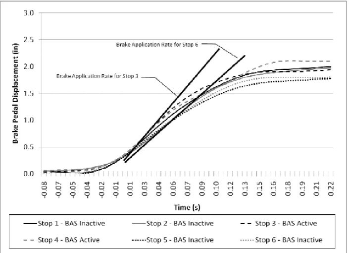
Figure 36. Average Stopping Distance by BAS Activation. All BAS Activations in the Figure 38. Average Corrected Stopping Distances for all BAS-Active Stops and BAS- Figure 39. Corrected Stopping Distances for BAS-Active and BAS-Disabled Braking Figure 40. Average Corrected Stopping Distance by BAS Activation Status for only Drivers Figure 41. Driver 10, an Older Male Driving the Mercedes-Benz R350, had a Corrected Figure 42. Driver 10, an Older Male driving the Mercedes-Benz R350, had a Corrected Figure 43. Driver 65, a Younger Female, Driving the Volvo S80 had a Corrected Stopping Figure 44. Driver 65, a Younger Female, Driving the Volvo S80, had a Corrected Stopping Figure 23. The brake application rate over the first 0.22 s for all six stops. ... 45
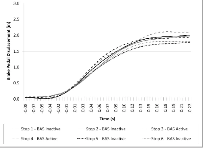
Figure 24.The brake application rate for Stops 3 and 6 over the first 0.03 s. ... 46
Figure 25. Data Acquisition System Mounted in the Trunk of the Volvo S80 ... 50
Figure 26. Multiplex View from Vehicle Cameras ... 51
Figure 27. Diagram of the Virginia Smart Road ... 52
Figure 28. Fifth Wheel and Hitch Setup on the Volvo S80 ... 54
Figure 29. Diagram Showing Measurement Locations on Brake Pedal Pad ... 54
Figure 30. Plot of Predicted Values for Pedal Travel in Percent and Inches ... 56
Figure 31. Brake Pedal Displacement First Inflection Point ... 57
Figure 32. Maximum Brake Pedal Displacement ... 58
Figure 33. Brake Pedal Modulation Example... 59
Figure 34. Location of Crossbow Inertial Measurement System in Mercedes-Benz R350 ... 60
Figure 35. Inflatable Barricade use for Unexpected Braking Maneuver ... 63
Anticipated Braking Maneuver Occurred using the Volvo S80 ... 72
Figure 37. Corrected Stopping Distances for BAS-Active and BAS-Inactive Stops ... 73
Inactive Stops in which ABS Activated in the Repeated Braking Session ... 78
Maneuvers Produced by Drivers that Activated BAS During the Repeated Braking Session ... 80
that Activated BAS in the Repeated Braking Session ... 81
Stopping Distance of 63.41 ft. in the R2 Braking Maneuver ... 82
Stopping Distance of 73.98 ft. in the R3 Braking Maneuver ... 83
Distance of 72.93 ft. in the R1 Braking Maneuver ... 84
Distance of 83.10 ft. in the R3 Braking Maneuver ... 85
Figure 45. Corrected Stopping Distance by BAS Activation in the Mercedes-Benz R350 ... 87
Figure 46. Corrected Stopping Distance by BAS Activation in the Volvo S80 ... 88
Figure 48. Maximum Brake Pedal Force for Drivers Assigned to the Mercedes-Benz R350 ... 91
Figure 50. Distribution of Brake Pedal Forces for Drivers Completing a Stop at an Figure 51. Distribution of Brake Pedal Forces for Drivers Completing a Stop at an Figure 52. Stages of Human Information Processing Relevant to Normal Braking Figure 57. All-weather testing equipment with experimental lighting test bed installed on the Figure 72. Driver 44, an older male driving the Volvo S80, activated ABS 2.35 seconds into Figure 73. Driver 47, an older male driving the Volvo S80, activated ABS 1.7 seconds into Figure 74. Driver 53, a younger female driving the Volvo S80, activated ABS 1.15 seconds Figure 49. Maximum Brake Pedal Force for Drivers Assigned to the Volvo S80 ... 92
Unexpected Barricade... 103
Anticipated Barricade ... 103
Performance ... 120
Figure 53. Stages of Human Information Processing Relevant to Panic-Braking Performance 121 Figure 54. Mercedes Benz R350 tire wear over the course of the study ... 133
Figure 55. Volvo S80 tire wear over the course of the study ... 134
Figure 56. Fog, rain, and snow equipment installed on the Smart Road. ... 139
Smart Road... 140
Figure 58. Bunker with DAS and weather station installed on the Smart Road. ... 141
Figure 59. Gate that restricts access to the Smart Road. ... 142
Figure 60. Smart Road control room and dispatcher monitoring research. ... 143
Figure 61. VTTI’s vehicle fleet on the Smart Road bridge. ... 144
Figure 62. Load Cell used in the study ... 146
Figure 63. Visual Acuity Chart Positioning... 162
Figure 64. Audiometer ... 165
Figure 65. Response Button... 165
Figure 66. Headphones ... 165
Figure 67. Ports ... 165
Figure 68. Power Cord Port ... 165
Figure 69. Power Switch ... 166
Figure 70. Keypad... 166
Figure 71. Braking Maneuver Library Legend ... 188
the panic-braking maneuver. ... 189
the panic-braking maneuver. ... 190
Figure 75. Driver 57, a younger male driving the Volvo S80, activated ABS 1.9 seconds into the panic braking maneuver. ... 192
Figure 76. Driver 9, an older male driving the Mercedes-Benz R350, did not activate ABS in
the braking maneuver. ... 193 Figure 77. Driver 11, an older male driving the Mercedes-Benz R350, did not activate ABS in the braking maneuver. ... 194
Figure 78. Driver 19, a younger female driving the Mercedes-Benz R350, did not activate
ABS in the braking maneuver. ... 195 Figure 79. Driver 23, a younger female driving the Mercedes-Benz R350, did not activate
ABS in the braking maneuver. ... 196
Figure 80. Driver 25, a younger male driving the Mercedes-Benz R350, did not activate ABS
in the braking maneuver. ... 197 Figure 81. Driver 29, a younger male driving the Mercedes-Benz R350, did not activate ABS in the braking maneuver. ... 198
Figure 82. Driver 59, a younger male driving the Mercedes-Benz R350, did not activate ABS
in the braking maneuver. ... 199 Figure 83. Braking Maneuver Library Legend ... 200
Figure 84. Driver 43, an older male driving the Volvo S80, activated BAS 0.1 second into the
anticipated braking maneuver. ... 201
Figure 85. Driver 44, an older male driving the Volvo S80, activated BAS 0.1 second into the
anticipated braking maneuver. ... 202
Figure 86. Driver 48, an older male driving the Volvo S80, activated BAS 0.1 second into the
anticipated braking maneuver. ... 203
Figure 87. Driver 58, a younger male driving the Volvo S80, did not activate BAS during the
anticipated braking maneuver. ... 204
Figure 88. Driver 65, a younger female driving the Volvo S80, did not activate BAS during
the anticipated braking maneuver. ... 205
Figure 89. Driver 69, an older male driving the Volvo S80, did not activate BAS during the
anticipated braking maneuver. ... 206 Figure 90. Braking Maneuver Library Legend ... 207
Figure 91. Brake pedal displacement over the first 4 seconds of the R1 panic braking
maneuver for Driver 10, an older male driving the Mercedes-Benz R350 ... 208
Figure 92. Brake pedal displacement over the first 4 seconds of the R2 panic braking
maneuver for Driver 10, an older male driving the Mercedes-Benz R350 ... 209
Figure 93. Brake pedal displacement over the first 4 seconds of the R3 panic braking
maneuver for Driver 10, an older male driving the Mercedes-Benz R350 ... 210
Figure 94. Brake pedal displacement over the first 3.5 seconds of the R1 panic braking
Figure 95. Brake pedal displacement over the first 3.5 seconds of the R2 panic braking
maneuver for Driver 21, a younger female driving the Volvo S80 ... 212
Figure 96. Brake pedal displacement over the first 4 seconds of the R3 panic braking
maneuver for Driver 21, a younger female driving the Volvo S80 ... 213
Figure 97. Brake pedal displacement over the first 4 seconds of the R1 panic braking
maneuver for Driver 26, a younger male driving the Mercedes-Benz R350 ... 214
Figure 98. Brake pedal displacement over the first 4 seconds of the R2 panic braking
maneuver for Driver 26, a younger male driving the Mercedes-Benz R350 ... 215
Figure 99. Brake pedal displacement over the first 4 seconds of the R3 panic braking
maneuver for Driver 26, a younger male driving the Mercedes-Benz R350 ... 216
Figure 100. Brake pedal displacement over the first 3.5 seconds of the R1 panic braking
maneuver for Driver 29, a younger male driving the Mercedes-Benz R350 ... 217
Figure 101. Brake pedal displacement over the first 3.5 seconds of the R2 panic braking
maneuver for Driver 29, a younger male driving the Mercedes-Benz R350 ... 218
Figure 102. Brake pedal displacement over the first 3.5 seconds of the R3 panic braking
maneuver for Driver 29, a younger male driving the Mercedes-Benz R350 ... 219
Figure 103. Brake pedal displacement over the first 4 seconds of the R1 panic braking
maneuver for Driver 43, a older male driving the Volvo S80 ... 220
Figure 104. Brake pedal displacement over the first 4 seconds of the R2 panic braking
maneuver for Driver 43, a older male driving the Volvo S80 ... 221
Figure 105. Brake pedal displacement over the first 4 seconds of the R3 panic braking
maneuver for Driver 43, an older male driving the Volvo S80 ... 222
Figure 106. Brake pedal displacement over the first 3.5 seconds of the R1 panic braking
maneuver for Driver 49, a younger male driving the Volvo S80 ... 223
Figure 107. Brake pedal displacement over the first 3.5 seconds of the R2 panic braking
maneuver for Driver 49, a younger male driving the Volvo S80 ... 224
Figure 108. Brake pedal displacement over the first 3.5 seconds of the R3 panic braking
maneuver for Driver 49, a younger male driving the Volvo S80 ... 225
Figure 109. Brake pedal displacement over the first 3.5 seconds of the R1 panic braking
maneuver for Driver 50, a younger female driving the Volvo S80 ... 226
Figure 110. Brake pedal displacement over the first 3 seconds of the R2 panic braking
maneuver for Driver 50, a younger female driving the Volvo S80 ... 227
Figure 111. Brake pedal displacement over the first 3.5 seconds of the R3 panic braking
maneuver for Driver 50, a younger female driving the Volvo S80 ... 228
Figure 112. Brake pedal displacement over the first 3.5 seconds of the R1 panic braking
maneuver for Driver 52, a younger female driving the Volvo S80 ... 229
Figure 113. Brake pedal displacement over the first 3.5 seconds of the R2 panic braking
Figure 114. Brake pedal displacement over the first 3 seconds of the R3 panic braking
maneuver for Driver 52, a younger female driving the Volvo S80 ... 231
Figure 115. Brake pedal displacement over the first 3.5 seconds of the R1 panic braking
maneuver for Driver 55, a younger female driving the Volvo S80 ... 232
Figure 116. Brake pedal displacement over the first 3 seconds of the R2 panic braking
maneuver for Driver 55, a younger female driving the Volvo S80 ... 233
Figure 117. Brake pedal displacement over the first 4 seconds of the R3 panic braking
maneuver for Driver 55, a younger female driving the Volvo S80 ... 234
Figure 118. Brake pedal displacement over the first 2.5 seconds of the R1 panic braking
maneuver for Driver 58, a younger male driving the Volvo S80 ... 235
Figure 119. Brake pedal displacement over the first 3.5 seconds of the R2 panic braking
maneuver for Driver 58, a younger male driving the Volvo S80 ... 236
Figure 120. Brake pedal displacement over the first 3 seconds of the R3 panic braking
maneuver for Driver 58, a younger male driving the Volvo S80 ... 237
Figure 121. Brake pedal displacement over the first 3.5 seconds of the R1 panic braking
maneuver for Driver 62, a younger male driving the Volvo S80 ... 238
Figure 122. Brake pedal displacement over the first 3.5 seconds of the R2 panic braking
maneuver for Driver 62, a younger male driving the Volvo S80 ... 239
Figure 123. Brake pedal displacement over the first 3.5 seconds of the R3 panic braking
maneuver for Driver 62, a younger male driving the Volvo S80 ... 240
Figure 124. Brake pedal displacement over the first 5 seconds of the R1 panic braking
maneuver for Driver 63, a younger male driving the Volvo S80 ... 241
Figure 125. Brake pedal displacement over the first 3 seconds of the R2 panic braking
maneuver for Driver 63, a younger male driving the Volvo S80 ... 242
Figure 126. Brake pedal displacement over the first 2.5 seconds of the R3 panic braking
maneuver for Driver 63, a younger male driving the Volvo S80 ... 243
Figure 127. Brake pedal displacement over the first 3.5 seconds of the R1 panic braking
maneuver for Driver 64, a younger male driving the Volvo S80 ... 244
Figure 128. Brake pedal displacement over the first 3.5 seconds of the R2 panic braking
maneuver for Driver 64, a younger male driving the Volvo S80 ... 245
Figure 129. Brake pedal displacement over the first 3.5 seconds of the R3 panic braking
maneuver for Driver 64, a younger male driving the Volvo S80 ... 246
Figure 130. Brake pedal displacement over the first 3.5 seconds of the R1 panic braking
maneuver for Driver 65, a younger female driving the Volvo S80 ... 247
Figure 131. Brake pedal displacement over the first 3.5 seconds of the R2 panic braking
maneuver for Driver 65, a younger female driving the Volvo S80 ... 248
Figure 132. Brake pedal displacement over the first 3.5 seconds of the R3 panic braking
Figure 133. Brake pedal displacement over the first 3.5 seconds of the R1 panic braking
maneuver for Driver 70, an older female driving the Volvo S80 ... 250
Figure 134. Brake pedal displacement over the first 3 seconds of the R2 panic braking
maneuver for Driver 70, an older female driving the Volvo S80 ... 251
Figure 135. Brake pedal displacement over the first 3 seconds of the R3 panic braking
LIST OF TABLES
Table 1. Summary of Corrected Stopping Distances by BAS Activation ... iv
Table 3. Corrected Stopping Distances Produced for Specified Brake Pedal Displacement Table 4. Corrected Stopping Distances Produced for Specified Brake Pedal Displacement Table 6. Corrected Stopping Distances Produced for Specified Brake Application Rates Table 7. Corrected Stopping Distances Produced from 45 mph at the Mercedes-Benz R350 Table 8. Corrected Stopping Distances Produced from 45 mph at the Mercedes-Benz R350 Table 9. Corrected Stopping Distances Produced by the Mercedes-Benz R350 from 45 mph Table 10. Corrected Stopping Distances Produced by the Mercedes-Benz R350 from 45 mph Table 22. Drivers that Activated BAS in the Repeated Braking Session Collapsed Across Table 23. Corrected Stopping Distances for BAS-Active and BAS-Disabled Braking Table 2. Drivers that Activated BAS in the Repeated Braking Session ... v
Magnitudes... 32
Magnitudes... 34
Table 5. Corrected Stopping Distances Produced for Specified Brake Pedal Force Magnitudes 35 (Holding Brake Pedal Force at 50 Percent) at 45 mph ... 37
BAS Activation Threshold with BAS Enabled... 38
BAS Activation Threshold with BAS Disabled... 38
Using Maximum Brake Controller Input and BAS Enabled ... 39
Using Maximum Brake Controller Input and BAS Disabled ... 39
Table 11. Corrected Stopping Distances for the Volvo S80 Braking Maneuvers ... 43
Table 12. Corrected Stopping Distances for the Volvo S80 Braking Maneuvers ... 44
Table 13. Driver 1 BAS Activation Tests Using the Volvo S80 ... 47
Table 14. Driver 2 BAS Activation Test Using the Volvo S80 ... 47
Table 15. Driver 3 BAS Activation Tests Using the Mercedes-Benz R350 ... 48
Table 16. Driver 4 BAS Activation Tests Using the Mercedes-Benz R350 ... 48
Table 17. Mercedes-Benz R350 Pedal Travel Measurements ... 55
Table 18. Volvo S80 Pedal Travel Measurements ... 55
Table 19. Drivers Who Stopped to Surprise Barricade ... 65
Table 20. Drivers Who Stopped at the Anticipated Barricade ... 69
Table 21. Corrected Stopping Distances Observed in the Repeated Braking Session ... 74
Vehicle ... 77
Maneuvers Produced by Drivers that Activated BAS during the Repeated Braking Session ... 79
Table 24. Corrected Stopping Distances by BAS Activation for the Mercedes-Benz R350 ... 90
Table 26. Corrected Stopping Distances for BAS-Active and BAS-Disabled Braking
Maneuvers Produced by Female Drivers that Activated BAS during the Repeated Braking
Session ... 94
Table 27. Corrected Stopping Distances for BAS-Active and BAS-Disabled Braking
Maneuvers Produced by Male Drivers that Activated BAS during the Repeated Braking
Table 28. Corrected Stopping Distances for BAS-Active and BAS-Disabled Braking
Maneuvers Produced by Older Drivers that Activated BAS during the Repeated Braking
Table 29. Corrected Stopping Distances for BAS-Active and BAS-Disabled Braking
Maneuvers Produced by Younger Drivers that Activated BAS during the Repeated Braking
Table 31. Driver Identification of BAS Activation Performance by Vehicle, Includes Only
Table 35. Comparison of Drivers who Stopped at the Unexpected Barricade to Drivers who
Table 36. Comparison of Drivers that Stopped in Both the Unexpected and Anticipated
Table 39. Modulation Scores for Drivers that Stopped in R1, R2, and R3 Using the Mercedes-
Table 40. Modulation Scores for Drivers that Stopped in R1, R2, and R3 Using the Volvo S80114 Session ... 94
Session ... 95
Session ... 96 Table 30. Driver Performance in Identifying BAS-Active Stops ... 97 Drivers Performing BAS-Activated Panic Braking ... 98 Table 32. Subjective Ranking of BAS Effectiveness Over Last Two Trials ... 99 Table 33. Overall Subjective Rating of BAS... 99 Table 34. Frequencies of Driver Responses ... 100 Stopped at the Anticipated Barricade ... 101 Barricade Stops ... 102 Table 37. Modulation Scores for those Drivers that Stopped to the Unexpected Barricade ... 112 Table 38. Modulation Scores for those Drivers that Stopped at the Anticipated Barricade ... 113 Benz R350... 113
Table 41. Modulation Scores by Test Vehicle Used... 114 Table 42. BAS Operational Mechanism ... 126 Table 43. Ability to Disable BAS by Operational Mechanism ... 127 Table 44. Cues to BAS Activation... 127 Table 45. BAS Actuation Style... 127 Table 46. Conditions Required for BAS Activation... 128 Table 47. Conditions Deactivating BAS Following Activation ... 128 Table 48. BAS Packet ID Reporting Status ... 129 Table 49. Ability to Disable BAS with PID ... 129
Table 50. BAS Driver Adaptation ... 129 Table 51. Target Population for BAS Assistance ... 130 Table 52. Vehicle offering BAS ... 131 Table 53. Capabilities and Scaling... 137 Table 54. Step Input Force Response with Output Blocked... 137 Table 55. Weight of the Components ... 137
CHAPTER 1. INTRODUCTION
The Brake Assist System (BAS) is a safety feature that supplements driver’s brake pedal effort during panic-braking maneuvers. BAS was co-developed by TRW and Daimler-Benz in the 1990s. Starting in 1997, BAS has been a standard feature on Mercedes-Benz vehicles. BAS was developed after simulator research demonstrated that many drivers fail to engage a vehicle’s maximum braking potential during panic stops. In particular, inexperienced drivers do not apply sufficient braking effort (i.e., brake pedal force) in emergency situations (Breuer, et al., 2007; Feigel & Schonlau, 1999; Sorniotti, 2006; Yoshida, 1998). Therefore, in addition to the proper engineering of the braking system, accounting for driver limitations in brake pedal application represents an additional approach for reducing the vehicle’s stopping distance.
The objective of this study was to evaluate how drivers perform avoidance maneuvers when using BAS-equipped vehicles. The human performance experimental methods described in this document were developed to determine how driving a vehicle equipped with an anti-lock brake system (ABS) compares to driving a vehicle equipped with both ABS and BAS during panic braking.
This study focused on driver performance. As such, BAS was evaluated from the user’s perspective, not that of the underlying mechanics or electronics. Since various types of BAS were available at the time of the study (such as mechanical or electronic BAS), it was considered possible that that braking performance could vary depending on the BAS type. To ensure that this study was relevant to future BAS designs, the opinions of original equipment manufacturers (OEM) and other experts on BAS trends were used to select the most appropriate system(s) for this study.
This final report includes seven chapters. Following this introduction, Chapter 2 presents the research questions of interest and the operational definitions used. As part of this research effort, the relevant literature was examined. Chapter 3 is an overview of the relevant literature on braking research. Before conducting the data collection for the study, a preliminary braking test was performed to evaluate the BAS. Chapter 4 presents the results of the BAS characterization and preliminary braking tests that were performed before the human performance evaluation experiment design was finalized. Chapter 5 presents the experimental design, methods, and results as they pertain to each of the research questions. The methods for this research effort took into consideration the knowledge gained from the literature review, expert opinion, preliminary braking test, and previous research performed at the Virginia Tech Transportation Institute (VTTI). Chapters 6 and 7 present the discussion and conclusions, respectively.
CHAPTER 2. RESEARCH QUESTIONS AND OPERATIONAL DEFINITIONS RESEARCH QUESTIONS
This project addressed 13 research questions. They are listed and functionally grouped below. The Brake Assist Effect
1. Overall, does BAS affect panic-braking stopping distance?
2. Do both BASs equally affect stopping distance?
3. Does BAS equally assist males and females?
4. Does BAS equally assist older and younger drivers?
5. Are drivers aware of the BAS activating?
6. Do drivers like the BAS?
Role of Expectancy
7. To what degree does expectancy affect panic-braking stopping distance?
8. Do drivers apply harder brake pedal force during unexpected braking maneuvers than
during anticipated braking maneuvers?
Driver Panic-braking Performance
9. Do male drivers apply the brakes with forces and displacements similar to female
drivers?
10. Do older or experienced drivers apply the brakes with forces and displacements similar to younger or less experienced drivers?
11. What initial pedal travel speed and displacement are characteristic of panic-braking maneuvers?
12. Can brake pedal displacement alone be used to identify panic braking? 13. Do drivers modulate their braking during panic-braking maneuvers?
OPERATIONAL DEFINITIONS
The following operational definitions are provided as a reference. Anticipated Braking Maneuver
BAS
BAS-Active Stop BAS-Disabled Stop
BAS-Inactive Stop
Brake Pedal Application Rate
Brake Pedal Displacement
Brake Pedal Force
Brake Pedal Modulation
Corrected Stopping Distance
Panic Braking Maneuver Repeated Braking Session
Unexpected Braking Maneuver
The braking maneuver drivers performed when the inflatable barricade deployment was known ahead of time.
Brake Assist System. A safety feature that supplements drivers’ braking upon detection of a rapid and vigorous brake pedal application.
A braking maneuver in which BAS activated.
A braking maneuver in which BAS cannot be activated by the driver because it is disabled.
A braking maneuver in which BAS was enabled, but did not activate.
A measure of how fast the driver presses on the brake pedal during the onset of braking.
How far the driver presses the brake pedal down during a braking maneuver.
The force the driver applies with his/her foot on the brake pedal.
The degree to which drivers ease up on, or increase the displacement of, the brake pedal after the initial brake pedal displacement is performed in a braking maneuver.
The distance travelled by the test vehicle from the point the driver’s foot touches the brake pedal to the point where the fifth-wheel measuring device stops incrementing (produces three consistent readouts in a row).
A braking maneuver in which ABS activates.
A series of three braking maneuvers in which drivers vigorously pressed the brake pedal in response to an auditory alarm in attempt to stop the vehicle as fast as possible.
The braking maneuver drivers performed in response to an inflatable barricade being unexpectedly deployed across the road.
CHAPTER 3. LITERATURE REVIEW IDENTIFYING PANIC-BRAKING
Hara, Ohta, Yamamoto, and Yoshida (1998) and Yoshida et al. (1998) cite research conducted internally at Toyota Motor Corporation in which the braking performance of 82 drivers, sampled from a wide range of age groups (18 to 70 years old, both male and female), was investigated in response to a surprise event. Participants were told to drive a test vehicle at 31 mph (50 km/h) along a mock city and suburban test track for 30 minutes. While on their way to the instructed destination (approximately 15 minutes into the drive), a surprise barricade protruded in front of the car at a time-to-collision (TTC) of 2 s. The opposite lane was configured to appear closed for construction. This prevented the participants from swerving in response to the surprise event. The purpose of the scenario was to observe panic-braking behavior. It was found that 47 percent of the drivers failed to apply sufficient brake pedal effort (brake pedal force) to engage ABS or produce wheel skid. Figure 1 plots pedal effort versus time for one representative experienced driver and one representative inexperienced driver. Yoshida et al. (1998) distinguish between sufficient and insufficient pedal effort, while Hara et al. (1998) describe the same data in terms of driver experience (Figure 2). Figure 2 also plots pedal effort for normal braking events by driver experience.
Figure 2. Pedal Effort Plotted against Time during Panic and Normal Braking (Adapted from Hara, Ohta, Yamamoto, & Yoshida, 1998)
Hara et al. (1998) highlight three key findings from this research (which correspond to the three number designations in Figure 2):
1) There was a significant difference in the initial brake pedal application rate between normal and panic-braking situations. Additionally, the initial brake pedal application rate (within the first 0.05 s of the stop) was the same for the experienced driver who could generate sufficient braking effort and the inexperienced driver who could not. 2) The initial pedal effort generated by the inexperienced driver was less than what the
experienced driver generated. In fact, the maximum pedal effort realized by the
inexperienced driver was less than one-third of that generated by the experienced driver. 3) The braking effort generated by the inexperienced driver decreased throughout the
braking maneuver (after 0.6 s).
Hara et al. (1998) state that these findings are representative of drivers of various ages and genders. Consequently, the research suggests that panic braking can be identified from the initial brake pedal application rate. Further testing showed that brake pedal displacement (the distance the brake pedal travels, also referred to as stroke in the literature) must also be considered because, in highway driving, a rapid initial brake pedal application rate frequently occurs in non-panic-braking scenarios. Fortunately, these non-non-panic-braking maneuvers are distinguishable from panic stops by their shorter pedal displacements.
HOW DOES BRAKE ASSIST WORK?
With the understanding that panic braking can be identified, two brake improvement strategies are possible. One is to apply maximum braking upon detection of panic braking, while the other is to apply maximum braking and modulate the amount of braking relative to the driver’s brake pedal input. It should be emphasized that although brake force is reduced when the driver’s brake pedal input is reduced in the braking maneuver, the instantaneous brake force for a given brake pedal input remains amplified. While the maximum braking option benefits inexperienced drivers who are unaccustomed to applying sufficient braking force, the unchanging application of maximum braking may annoy experienced drivers who modulate their braking input to control their vehicle. For this reason, Toyota elected to adopt the second strategy since it retains the pedal feel associated with comfortable and well proportioned braking that drivers are accustomed to (Feigel & Schonlau, 1999; Hara, et al., 1998).
Figure 3 shows how BAS allows drivers to maintain control of the braking operation while supplementing braking effectiveness. Note that the change in brake effectiveness (brake fluid pressure at the wheel cylinders) at each stage of the braking operation is modulated relative to driver brake input (master cylinder pressure).
Figure 3. Pressure Control during Panic Braking (Adapted from Hara, Ohta, Yamamoto, & Yoshida, 1998)
TYPES OF BRAKE ASSIST
There are various BAS designs. One predominant classifier is whether they are electronic or mechanical. Toyota has published technical papers on three types of electronic BAS: 1) vacuum
booster, 2) pump-motor-applied, and 3) hydraulic servo (accumulated pressure applied) (Yoshida, 1998). Continental Teves, the supplier to Mercedes-Benz, has also published papers on their electronic and mechanical vacuum booster BAS (Feigel & Schonlau, 1999).
Unfortunately, automobile manufacturers have only sparsely published technical papers describing the BAS functionality, effectiveness, and methods used to evaluate driver
performance. The following section summarizes the BASs that have been reported in the public domain.
Electronic Brake Assist Systems Vacuum Booster Brake Assist
The vacuum booster BAS is a modification of the vehicle’s existing brake booster (Figure 4). Brake boosters are devices that increase the ratio of braking force to pedal force. The brake booster accomplishes this by utilizing pressure differences between two pneumatic chambers to generate a large force on the vehicle’s hydraulic brake system. Specifically, the constant pressure chamber (on the master cylinder side) and the transformation chamber (on the brake pedal side), as shown in Figure 5, are separated by a diaphragm and both are kept under vacuum pressure when the booster is inactive. When the driver steps on the brake pedal, air (which is at a higher atmospheric pressure than the partial vacuum) is let into the transformation chamber. The pressure differential causes the diaphragm to slide in order to reduce the volume of the constant pressure chamber and equalize the pressure on either side. The diaphragm connects to the output rod, which in turn leads to an increase in pressure of the brake fluid in the brake lines (Yoshida, 1998).
Figure 4. Diagram Illustrating how Vacuum Booster BAS and Other Braking Elements are Connected (from Yoshida et al., 1998)
Figure 5. Components of Vacuum Booster BAS (From Yoshida et al., 1998) The vacuum booster BAS leverages this concept to generate high braking forces during panic braking. An auxiliary transformation chamber is placed on the constant-pressure-chamber side of the booster and is separated from it by a sub-plate (Figure 5). When panic braking is detected by the ABS and BAS/electronic control unit (ECU), a solenoid valve connected to the auxiliary chamber opens, allowing air to enter the auxiliary chamber. The result is an extra force on the output rod. Here, panic braking is detected by comparing brake pedal travel speed and pedal stroke to adaptable thresholds (Feigel & Schonlau, 1999). A feature of this booster design is that it allows the driver to modulate the vehicle’s deceleration by using the generic portion of the booster system while achieving amplified braking with the auxiliary booster (Yoshida, 1998). Note that the constant pressure chamber depicted in Figure 5 is actually a vacuum chamber. Pump-Motor-Applied Brake Assist
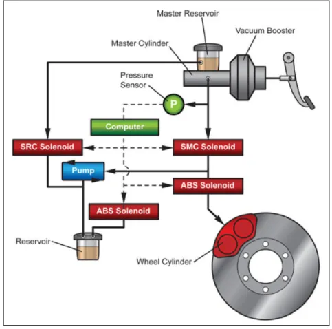
The pump-motor-applied BAS boosts braking performance by using the vehicle’s existing motor-controlled ABS pump (Yoshida, 1998). Upon detection of panic braking, brake effectiveness is increased by energizing (rotating) the ABS pump, closing the fluid-pressure shut-off valve (SMC) and opening the inlet valve (SRC) to take in brake fluid from the master reservoir (Figure 6). Brake fluid pressure is increased at a constant rate while the inlet valve is open, as depicted in area 1 of Figure 3. When the driver maintains brake pedal effort, both the shut-off and inlet valves are closed, preventing further intake of brake fluid from the reservoir
and maintaining the achieved system-assisted braking force. This stage is shown in area 2 of Figure 3. The ABS pump continues to rotate throughout the cycle in case the driver presses the brake again after it is released. An advantage of this system is its flexibility in modulating the pressure at each caliper. To facilitate controlled braking, when the brake pedal force is reduced by the driver, the off valve is opened while the inlet valve is kept closed. The opened shut-off valve allows brake fluid to return to the master cylinder, reducing the system-assisted braking force. Controlled braking in which braking effectiveness is reduced as the driver releases the brake pedal, is achieved by two control actions. First, the rate at which brake pressure drops is determined by the speed with which the brake pedal is released. Second, the amount of brake pressure that drops is determined by how far the brake pedal moves when released. By controlling the rate and amount of reduced braking, the system attempts to reflect the driver’s braking intentions. It is important to note that since inexperienced drivers tend to reduce their brake pedal effort during panic stops, the BAS incorporates an insensitive zone to slow the decrease in assisted braking force when foot pressure on the brake pedal is slowly reduced. These functions are shown in areas 3 and 4 in Figure 3. If the driver increases brake pedal force again (as shown in area 5 of Figure 3), the rate with which assisted braking returns is determined by the speed of brake pedal depression while the amount of assisted braking is determined by the magnitude of brake pedal depression (Yoshida, 1998).
Figure 6. Components of Pump-motor-applied BAS (from Hara, Ohta, Yamamoto, &
Hydraulic Servo (Accumulated Pressure Applied) Brake Assist
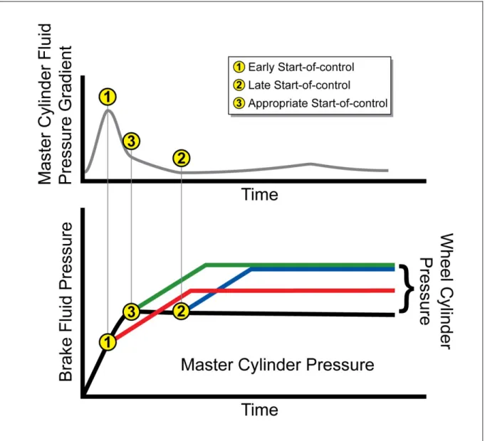
The hydraulic servo BAS supplements braking force by using accumulated fluid pressure that exists in the hydraulic servo brake system accumulator (Figure 7). It appears that the hydraulic servo BAS uses a brake fluid pressure sensor in lieu of pedal travel speed and pedal stroke to assess panic braking. During panic braking, there is an uncommonly large rise in the brake pressure gradient. When the fluid pressure sensor output exceeds a control threshold value, the accumulator fluid pressure is fed into the booster by opening the accumulator fluid pressure cutoff valve (STR solenoid), the regular fluid pressure cutoff valve (SA3 solenoid), and the fluid pressure change-over valve (SA1 solenoid). This system also allows for the modulation of pressure at each caliper, but detail on how this is accomplished is not provided (Yoshida, 1998).
Figure 7. Hydraulic Servo Brake (Accumulated Pressure Applied) BAS (from Yoshida et al., 1998)
Advantages of Electronic Brake Assist
An advantage of electronic BAS is the parameterization of activation criteria. The panic-braking thresholds can adapt to different basic vehicle versions and changing operating conditions, such as vehicle speed and driver braking behavior (Feigel & Schonlau, 1999). Tailoring BAS to the vehicle and driver takes full advantage of what the technology offers.