Virtual Environments through
Computer Vision
Richard Bowden (1), Tony Heap(2), Craig Hart(2)
(1) Dept of M & ES
(2) School of Computer Studies
Brunel University
University of Leeds
Uxbridge
Leeds LS6 9JT
Middlesex UB8 3PH
Tel: 01895 274000 ex 2915
Fax: 01895 812556
e-mail: [email protected]
url: http://http2.brunel.ac.uk:8080/~empgrrb/
This paper outlines a system design and implementation of a 3D input device for graphical applications. It is shown how computer vision can be used to track a users movements within the image frame allowing interaction with 3D worlds and objects. Point Distribution Models (PDMs) have been shown to be successful at tracking deformable objects. This system demonstrates how these ‘smart snakes’ can be used in real time with real world applications, demonstrating how computer vision can provide a low cost, intuitive interface that has few hardware constraints. The compact mathematical model behind the PDM allows simple static gesture recognition to be performed providing the means to communicate with an application. It is shown how movement of both the hand and face can be used to drive 3D engines. The system is based upon Open Inventor and designed for use with Silicon Graphics Indy Workstations but allowances have been made to facilitate the inclusion of the tracker within third party applications. The reader is also provided with an insight into the next generation of HCI and Multimedia. Access to this work can be gained through the above web address.
1. Introduction
Recent developments in processing power and multimedia technology has brought the capabilities of both real-time computer vision and high power graphics to the workstation user. As multimedia grows it is not unfeasible to imagine all workstations having some form of camera for video conferencing capabilities. This simple and relatively inexpensive piece of hardware allows the possibility for a new form of interacting with computers. Pentland has already shown how cameras and computer vision can be used to monitor a human within an environment providing an intelligence that allows environments to react to a user’s actions (Pentland, 1996). In the following text it will be shown how computer vision can be used to replace existing devices providing a simple way of interacting in 3D with computers.
Many researchers have proposed solutions to the problem of tracking humans in images (Ahmad, 1995; Lee, 1995; Uras, 1995; Yow, 1995; Baumberg, 1995). Various approaches have been suggested but one that has seen increasing popularity in recent years is the Point Distribution Model or PDM (Cootes, 1995). Since the introduction of the PDM and its applied name ‘Active Contour’ or ‘Smart Snakes’ a variety of applications have been suggested. Simple models have shown great success in the tracking of traffic, walking pedestrians, human hands and faces. Although a successful approach, heavy constraints are normally placed upon the models to provide a robust system. In vehicle tracking the ground plane constraint is often used to simplify the model. A similar approach is used by Ahmad
et al where the users hand is tracked as if using an invisible mouse (Ahmad, 1995).
The system uses point distribution models (Cootes, 1995) to track the users hand and face within the image frame. Deformation of objects is built into the PDM in order that it can locate and track an object through its various shapes. The resulting state of the model along with its position and rotation is passed to the graphical application where it can be used to animate models or move cameras within the scene.
2. Point Distribution Models
Point distribution models are used to produce a generic and flexible template that can be used to track any 2D deformable object. A weak perspective model (scaled orthographic) is used to provide 3D spatial information about the model and its position in a camera co-ordinate system. To locate and track the hand, a contour which has a similar shape is applied to an image. The process is an iterative one where the contour makes small steps within the image in order to find a natural resting place. The model uses suggested movements from control points (using edge detection or grey level matching). Movement of the model is allowed through the relocation of the model within the image, and deformation of the model within the bounds of the of the shape deviation gained from a training set.
As contours are used, this provides a robust system that can successfully track a users movements in real time regardless of skin pigmentation or background clutter. Two models are presented which can be combined to provide a generic flexible tool for interaction.
2.1 Building Statistical Models
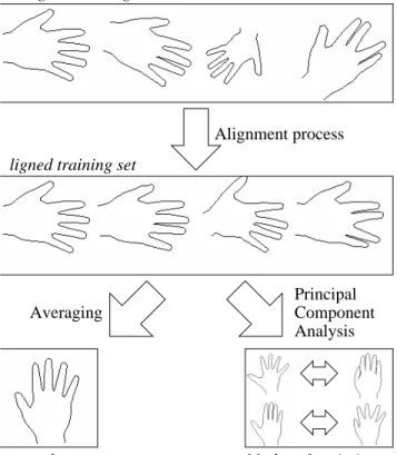
In order to successfully track a feature in an image frame an internal model of the object to be tracked is used. This model can be represented statistically using principle component analysis. To build a PDM it is first necessary to acquire a training set of shapes that represents the normal deformation of the object. Fig 1 gives an overview of the process of building a such a model.
ean shape
Alignment process
Modes of variation naligned training set
ligned training set
Principal Analysis Component Averaging
Figure 1 : Training a Point Distribution Model
Each pose of the model is described by a vector xe = (x1, y1, . . . ,xN ,yN), representing a set of points specifying the outline of an object. A training set of E vectors is assembled for a particular model class. The training set is then aligned (using translation, rotation and scaling) and the mean shape calculated by finding the average vector. To represent the deviation within the shape of the training set Principle Component Analysis (PCA) (Kendall, 1980) is performed on the deviation of the example vectors from the mean. In order to do this the covariance matrix S of the deviation is first calculated :
The t unit eigenvectors of S corresponding to the t largest eigenvalues supply the variation modes; t will generally be much smaller than N, thus giving a very compact model. It is
this dimensional reduction in the model that enables simple gesture recognition. A deformed shape x is generated by adding weighted combinations of vj to the mean shape :
x
x
b
jv
j j t=
+
=∑
1where bj is the weighting for the jth variation vector. Suitable limits for bj are ±3
λ
j , wherej
λ
is the jth largest eigenvalue of S. The hand model uses a mean shape that corresponds to a relaxed open pose hand and will deform and track a hand in real time using only the first four modes of variation (the four eigenvectors that correspond to the largest four eigenvalues). The model hand shape is described solely in terms of these vectors and the mean shape, these along with its position in 2D image space (x, y) , its size and rotation allow the model all the flexibility needed to track a hand within an image frame.2.2 The Hand Model
Figure 2 shows the primary mode of variation of the hand model after PCA has been performed, the readers attention is brought to the movement of this primary mode which encompasses the majority of deviation within the training set. This primary mode is closely linked to the movement of the thumb.
Figure 2 : Primary Mode of Hand Model
2.3 The Face Model
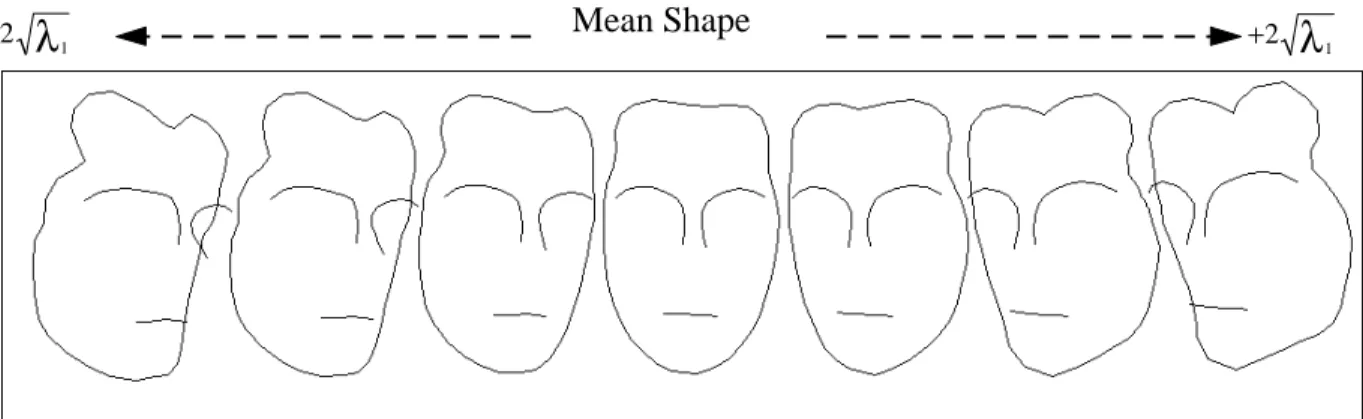
Figure 3 shows the primary mode of variation of the head model. Here it can see that the primary mode is directly linked to the rotation of the head and this primary mode can be used in conjunction with the position scale and rotation to give a 5th degree of freedom.
(2)
−2
λ
1 Mean +2λ
1Shape
−2
λ
1 Mean Shape +2λ
13 Recognising Gestures
The model is a fixed 2D outline of a hand in an open pose providing a robust system that facilitates accurate tracking in 3D. However this limits the gestures that can be recognised. Each shape of the model is represented by the values of the weights along the four primary modes of variation. Each shape therefore produces a distinct 4D feature vector that can be used for pattern recognition. PDMs allow considerable dimensional reduction, the model consisting of 61 points generating a 122 dimensional shape vector can be reduced to 4 dimensions through PCA. It is therefore possible to recognise static gestures from the values of these four weights.
Gestures were selected so as to be as intuitive as possible whilst attempting to separate individual gestures into distinct clusters within the 4D Gesture Space. A positive training set was produced directly from running the handtracker that consisted of the gestures to be recognised. Deviation from specific gestures (noise) was introduced to allow generalisation to be possible during pattern recognition. The final training set contained approximately 2,500 4D feature vectors. Due to the positive training set and similar model poses corresponding directly to similar feature vectors it would therefore be expected that each gesture would occupy a distinct, finite, cluster in Gesture Space.
As static gestures are of primary concern, the clusters can simply be approximated and extracted through the use of k-means cluster analysis without any prior knowledge of their nature. This enables much larger dimensional problems to be solved for complex models and therefore lends itself directly to 3D PDMs (see Future Work). As the move to dynamic gestures is considered, it is the Author’s opinion that neural networks would provide a more suitable solution. It has already been shown that American Sign Language (ASL) can successfully be recognised through the use of a data glove and a neural network (Fels, 1990). Working with a PDM provides a significantly smaller dimensional problem than that of a data glove with its multiple flexation sensors and therefore again demonstrates the beauty/simplicity of the PDM.
Ahmad et al proposed a similar approach to recognising gestures in a model of a hand placed flat on a workspace and manipulated similar to an invisible mouse (Ahmad, 1995). The model used encompasses larger deviation in model shape but at the cost of reliability.
4 Camera Calibration
In order for the output from the handtracker to be of any use to an application, it is important to calibrate the camera to provide meaningful communication between applications. The intrinsic and extrinsic parameters of the IndyCam1 were determined using a weak perspective model (scaled orthographic). This is possible due to the nature of the model being primarily 2 dimensional. Using this model results in a direct relationship between image size in pixels and real world object size/position in meters. The system is designed to work in an operational spatial cube of 0.5 x 0.5 x 0.5 metres. The movement of the hand within this space is normalised to the range -1,1 in the x, y and z directions.
This allows simple use of the tracker in applications where an appropriate scaling can be used.
5 Open Inventor
Open Inventor is a library of objects and methods used to create interactive 3D graphics applications. Inventor focuses on creating 3D objects. All information about these objects; their shape, size, colouring, surface texture, location in 3D space, is stored in a scene database or scene graph (Wernecke 1994). This is a tree structure that allows the entire scene to be represented within one hierarchical design, allowing complex objects to be assembled from simple primitives. As well as the existence of the scene graph it is necessary for the reader be familiar with the idea of a viewer and camera. Cameras in Inventor are nodes within scene graphs that tell the hardware how to render the graph (they specify the users view of the scene). Viewers are used as the user interface to applications and translate x events generated by mouse movement into events that control the camera position, orientation, state of the graph and interaction with objects.
Inventor uses a window-based system and allows interaction with the scene graph primarily through the use of a mouse, but also devices such as the space ball. It is important that the existing user interface not be compromised by the inclusion of the tracker. The tracker is therefore designed to work with the existing user interface, duplicating many of its features, and using automatic re-calibration.
6 System Overview
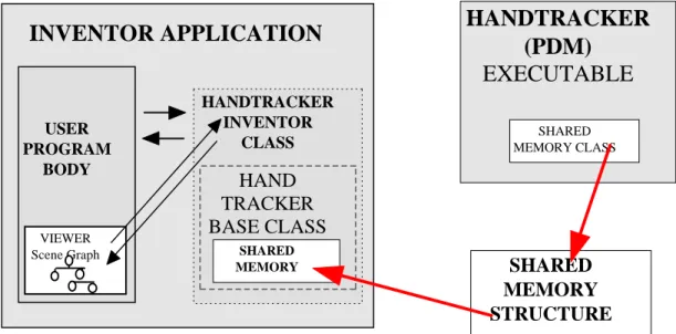
Figure 4 shows the system overview for the tracker. The PDM is contained within a separate executable that uses the IndyCam to track the movement of a user’s hand through 4 degrees of freedom (DOF)(x, y, z, and rotation about z) and head through 5 DOF. The image
Figure 4 : The System Overview.
SHARED MEMORY STRUCTURE
INVENTOR APPLICATION
USER PROGRAM BODY HANDTRACKER INVENTOR CLASS HAND TRACKER BASE CLASSHANDTRACKER
(PDM)
EXECUTABLE
SHARED MEMORY SHARED MEMORY CLASS VIEWER Scene Graphfrom the tracker is displayed within a small window with the PDM overlaid to allow the user to monitor its progress. Fast inter-process communications are provided through a shared memory segment that allows the information from the tracker to be incorporated within the Inventor application.
Communication between applications through the shared memory segment is handled through a shared memory class that provides both guaranteed and un-guaranteed transmission of data structures. The current location of the hand/face in normalised 3D space is constantly written to the memory structure with no guarantee of data transmission. As the nature of Inventor applications means that the application will only look at the memory segment when needed, this ensures that information read from the memory segment is always up to date. When a gesture is detected within the PDM a guaranteed data transmission is required to ensure that the application acts upon it if necessary. In this instance the data within the shared memory is locked until acknowledged from the application. For completeness the shared memory class uses a fixed size buffer to buffer information in the event of multiple consecutive gestures occurring.
The handtracker base class contains the shared memory class and handles the basic communications between the applications providing an easily interface to the handtracker for any application. The handtracker Inventor class provides higher level functions and will automatically alter the viewer, camera and scene graph depending upon the users actions and the present mode of operation.
6.1 The Handtracker 6.1.1 Modes of Operation
There are three basic modes of operation, each performing a specific function.
• Hand Mouse Mode
• Walk Viewer Mode
• Examiner Mode
In Hand Mouse mode the movement of the user’s hand is tracked and mimicked exactly within the environment by a virtual hand. This allows the user a virtual presence within the environment and a 3D pointer with which to interact with objects. The movement of the thumb makes a grasping action where the function of this action is user definable. In many cases it selects an object or ‘picks up’ that object.
In Walk Viewer mode the user’s movement controls the movement of the camera and allows the illusion of walking through an environment. Movement in the x, y and z direction move the camera respectively and rotation of the hand rotates the camera about its own y axis giving the illusion of turning.
In Examiner Viewer mode the user’s movement moves the camera on the surface of an imaginary sphere. Movement in the x and y direction moves the camera on the surface of this sphere respectively. Movement in the z direction changes the radius of the sphere and gives the illusion of zooming in and out and rotation of the scene.
Figure 5 : The Handtracker in Operation
The transition between modes of operation is done through the use of gestures. The nature of the modes of operation allow the user to interact in real time with applications/environments of different types. A virtual environment can be navigated in Walk Viewer mode until a particular area of the environment is located. This can then be examined further using the Examiner Mode and interaction is facilitated with the environment and objects in 3D through the use of the Hand Mouse Mode.
Gestures are fixed to that of basic tasks except the movement of the thumb which is user-definable allowing the application programmer to provide the interaction required for specific applications. All other gestures are reported to the application and allow further extension to their function. At the level of the Handtracker base class all recognised gestures perform no specific function but are reported to the user interface to provide as generic an input device as possible.
Figure 5 shows the handtracker in operation. The small window in the top left is the view from the camera, with the PDM overlay. The larger window contains the Inventor application. The scene is of a modelled terminal and is in Hand Mouse Mode. As the user moves the hand in x, y and z so the virtual hand will move within the scene. Note the widgets on the inventor application. These are the standard user interface to Inventor and are accessed through the use of the mouse. These work with the handtracker and allow either or both user interfaces to be used. The hand turns transparent when not in use so as not to obscure the users view. The handtracker is based upon the base viewer, so any user defined viewer will work with the handtracker providing it has been built upon the base class viewer. The handtracker monitors the state of the Inventor application and if any changes are made within the scene graph that were not performed by the handtracker it automatically re-calibrates its self.
6.2 The Headtracker
Figure 6 shows the head tracker in operation. Here a graphical representation of a head emulates the movements of the user’s head in the image frame. Here it can be seen how the primary mode of variation of the model is allowing the animation to rotate around its y-axis in addition to rotation around the z y-axis gained from the rotation of the PDM in the image frame.
Figure 6 : The Headtracker in Operation
The head tracker can be used to move the camera position as the user’s head moves. This gives additional 3D queues about a scene to a user allowing occluded regions to be exposed as the user looks around a scene.
7 Applications and Future Work
The handtracker is available in its development form from the web address allowing the inclusion of the tracking in any Inventor application. In addition to this a simple object viewer and a VRML1.0 viewer for Mosaic are available. The head tracker is available in its development form only. Models that allow more deformation have been examined for the
handtracker but with this additional deformation under the linear model of a PDM makes for a less robust system. Several approaches to Non-linear PDMs have been proposed (Sozou, 1994; Sozou, 1995; Heap, 1995) however these require additional computational work on the part of the model, making tracking slower. As usability is an important issue a fast non-linear approximation would provide a compromise between speed and reliability. The natural progression of this work is to a full 3D model. Heap et al (Heap, 1996) has demonstrated a linear version of a 3D hand PDM which although shows a significant decrease in response time demonstrates the future of this technology.
It is hoped by taking the PDM into the stereo domain that a sufficiently accurate system can be designed to allow a stereoscopic desktop VR system to be implemented. Using a pair of shutter glasses it is possible to place models in front of the plane of a monitor screen for a semi-imersive experience. The handtracker uses a virtual hand model in the environment to represent the user, bringing the models into our world would allow the user to use his own hand in the environment. A similar handtracking system could then be used to allow interaction with these objects.
As has been demonstrated with the tracking of a user’s head, a computer model can be used to emulate a user’s movemets. The resulting information conveying the current state of the head is small compared to that of a video stream. Possible applications of such technology could include video conferencing and shared workspaces. The rationale of such technologies is the need for visual contact between parties to aid the communication process. A VRML model of a head could be downloaded along with a texture of the users face to be overlaid on the model. Once downloaded, this model can be manipulated in real-time in conjunction with an audio stream. A specific model can be built to encompass the basic movement of facial features as humans talk. This information manifesting itself as deformation within the model is contained within the primary modes (as is rotation) and can be extracted from the weights applied to these modes. The introduction of the standard VRML2 should make this a feasible application.
References
Ahmad, T., Taylor, C. J., Lantis, A., & Cootes, T. F. (1995). Tracking and Recognising Hand Gestures Using Statistical Shape Models. Paper presented at the British Machine Vision Conference 1995, BMVC'95, University of Birmingham, Birmingham, UK.
Baumberg, A., & Hogg, D. (1995). An Adaptive Eigenshape Model. Paper presented at the British Machine Vision Conference 1995, BMVC'95, University of Birmingham, Birmingham, UK.
Cootes, T. F., Taylor, C. J., Cooper, D. H., & Graham, J. (1995). Active Shape Models -Their Training and Application. Computer Vision and Image Understanding, 61(1), 38-59.
S. S. Fels and G. E. Hinton (1990), Building Adaptive Interfaces with Neural Networks: The Glove-Talk Pilot Study, Human-Computer Interaction - INTERACT ‘90, Diaper, D et al (eds), pp 683-688, Elsevier Science Publishers B.V. (North-Holland).
Heap, A. J., Hogg, D. C. (1996), 3D Deformable Hand Models. Paper presented at Gesture Workshop 1996, University of York, York, UK.
Lee, J., & Kunii, T. L. (1995). Model-Based Analysis of Hand Posture. IEEE Computer Graphics and Applications, Sep, 77-86.
Pentland, A. P. (1996, April). Smart Rooms. Scientific American, pp. 54-62.
Sozou, P. D., Cootes, T. F., Taylor, C. J., & Di-Mauro, E. C. (1994). A Non-linear Generalisation of PDMs using Polynomial Regression. Paper presented at the British Machine Vision Conference 1994, BMVC'94, University of York.
Sozou, P. D., Cootes, T. F., Taylor, C. J., & Di Mauro, E. C. (1995). Non-Linear Point Distribution Modelling using a Multi-Layer Perceptron. Paper presented at the British Machine Vision Conference 1995, BMVC'95, University of Birmingham, Birmingham, UK.
Uras, C., & Verri, A. (1995). Sign Language Recognition: an Application of the Theory of Size Functions. Paper presented at the British Machine Vision Conference 1995, BMVC'95, University of Birmingham, Birmingham, UK.
J. Wernecke (1994), The Inventor Mentor, Addison-Weslet Publishing Company.
J. Wernecke (1994), The Inventor Toolmaker, Addison-Weslet Publishing Company.
Yow, K. C., & Cipolla, R. (1995). Towards an Automatic Human Face Localization System. Paper presented at the British Machine Vision Conference 1995, BMVC'95, University of Birmingham, Birmingham, UK.