Cognitive Network Framework for
Heterogeneous Wireless Mesh Systems
Ahmed S. K. Al-Saadi
Cardiff University
School of Engineering
This thesis is submitted in fulfilment of the requirement of the degree of
Doctor of Philosophy
I
Declaration and Statements
DECLARATION
This work has not previously been accepted in substance for any degree and is not being concurrently submitted in candidature for any degree.
Signed... (candidate) Date ...
STATEMENT 1
This thesis is being submitted in partial fulfilment of the requirements for the degree of PhD.
Signed ... (candidate) Date ...
STATEMENT 2
This thesis is the result of my own investigation, except where otherwise stated. Other sources are acknowledged by giving explicit reference.
Signed ... (candidate) Date ...
STATEMENT 3
I hereby give consent for my thesis, if accepted, to be available for photocopying and for inter-library loan, and for the title and summary to be made available to outside organizations.
Signed ... (candidate) Date ...
STATEMENT 4
I hereby give consent for my thesis, if accepted, to be available for photocopying and for inter-library loan, after expiry of a bar on access approved by the Graduate Development Committee.
II
ABSTRACT
Heterogeneous wireless mesh networks (WMN) provide an opportunity to secure higher network capacity, wider coverage and higher quality of service (QoS). However, heterogeneous systems are complex to configure because of the high diversity of associated devices and resources. This thesis introduces a novel cognitive network framework that allows the integration of WMNs with long-term evolution (LTE) networks so that none of the overlapped frequency bands are used. The framework consists of three novel systems: the QoS metrics management system, the heterogeneous network management system and the routing decision-making system. The novelty of the QoS metrics management system is that it introduces a new routing metric for multi-hop wireless networks by developing a new rate adaptation algorithm. This system directly addresses the interference between neighbouring nodes, which has not been addressed in previous research on rate adaptation for WMN. The results indicated that there was a significant improvement in the system throughput by as much as to 90%. The routing decision-making system introduces two novel methods to select the transmission technology in heterogeneous nodes: the cognitive heterogeneous routing (CHR) system and the semantic reasoning system. The CHR method is used to develop a novel reinforcement learning algorithm to optimise the selection of transmission technology on wireless heterogeneous nodes by learning from previous actions. The semantic reasoning method uses ontologies and fuzzy-based semantic reasoning to facilitate the dynamic addition of new network types to the heterogeneous network. The simulation results showed that the heterogeneous network outperformed the benchmark networks by up to 200% of the network throughput.
III
ACKNOWLEDGEMENT
First, I am grateful to Allah (My Lord) the all high, the all great who made it possible for me to finish this work.
Second, I would like to thank my supervisors, Professor Rossitza Setchi, Doctor Yulia Hicks, and Doctor Stuart Allen not only for their constant assistance, excellent guidance, and thoughtful advice, but also for their constant support and encouragement. The high standard of their research has always been an inspiration to me.
I would like also to thank my colleagues in Knowledge Engineering Systems (KES) group, Dr. Bennasar, Dr. Romli, Dr. Anuar, and Mrs. Harbi for stimulating discussion. Finally, I would like to express my sincere gratitude and appreciation to my beloved family: my father, mother, wife and sisters, for their endless love, support and prayers. I am fully aware of the fact that this thesis would have never been completed without the love, care and understanding of my dear wife.
IV
Table Contents
Declaration and Statements ……….…….I Abstract……….II Acknowledgment ..………....III Table of Contents ...………..………IV List of Figures...………..……...………...……VII List of Tables………...……….…..X List of Abbreviations………...………...XI List of notations ……… XVI List of Publications………...……….……….……….XIX
... 1
Introduction to Communication Networks ... 1
Motivation ... 4
Aim and Objectives ... 7
Thesis Outline ... 8
... 10
Wireless Networks ... 10
IEEE 802.11 Wireless LANs ... 11
V
Wireless Mesh Network ... 15
Routing Protocols in WMNs ... 17
Routing Metrics in WMNs ... 18
Transmission Rates in IEEE 802.11 ... 21
Rate Adaptation Based on Frame Loss Statistics ... 22
Rate Adaptation Based on Traffic Estimation ... 23
Throughput-Aware Rate Adaptation ... 24
Receiver-Based Rate Adaptation ... 24
Heterogeneous Wireless Networks ... 24
Cognitive Networks ... 27
Semantic Technologies... 29
Ontology ... 29
Semantic Reasoning ... 33
Semantic Technologies for Wireless Networks ... 33
Reinforcement Learning... 36
Fuzzy Interference ... 38
Summary ... 42
... 45
Cognitive Network Framework ... 46
System Modelling ... 50
Summary ... 53
... 54
IEEE 802.11 Transmission Rates ... 55
Rate Adaptation Based on Reinforcement Learning ... 56
Performance Evaluation... 61
Simulation Setup ... 61
Evaluating and Validating Results ... 62
Summary ... 70
VI
System Architecture ... 73
Heterogeneous Routing Protocol ... 75
Heterogeneous Routing Tables ... 75
Cognitive Heterogeneous Routing Algorithm ... 78
Performance Evaluation... 85
Simulation Setup ... 85
Evaluating and Validating Results ... 85
Summary ... 99
... 101
Network Layout ... 102
Semantic System for Heterogeneous Network ... 104
Heterogeneous Network Ontology ... 105
Fuzzy-based Knowledge Base ... 107
Semantic Rule-base and Fuzzy-based Reasoning System ... 113
Performance Evaluation... 121
Urban Heterogeneous Network ... 122
VANET Heterogeneous Network ... 127
Summary ... 132
... 134
Contributions ... 134
Conclusions ... 137
Limitations and Future Work ... 140
VII
List of Figures
Figure 1-1: TCP/IP network layers ... 4
Figure 2-1: VANET network example ... 13
Figure 2-2: LTE network architecture (Firmin and 3GPP MCC 2014) ... 14
Figure 2-3: WMN architecture ... 16
Figure 2-4: The cognition loop (Facchini 2011) ... 28
Figure 2-5: Ontology graph example ... 30
Figure 2-6: XML excerpt of a network ontology ... 32
Figure 2-7: Standard reinforcement learning model (Kaelbling et al. 1996; Jiang 2011) ... 37
Figure 2-8: Various shapes of commonly used membership functions. ... 40
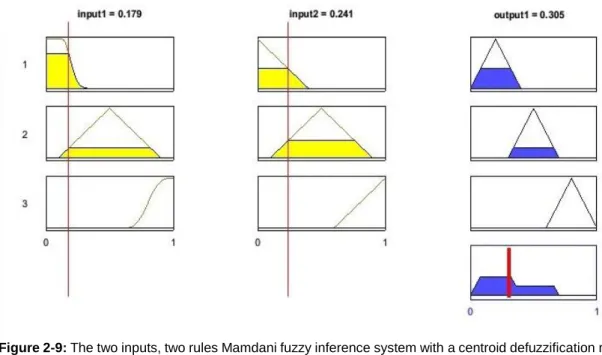
Figure 2-9: The two inputs, two rules Mamdani fuzzy inference system with a centroid defuzzification result. ... 42
Figure 3-1: Cognitive network framework ... 46
Figure 3-2: Detailed description of the cognitive framework. ... 48
Figure 3-3: Overview of the LENA model (LENA n.d.). ... 52
Figure 4-1: Data rate compared with coverage (Florwick et al. 2011). ... 56
Figure 4-2: RARE flowchart. ... 58
Figure 4-3: Wireless mesh network grid configuration. ... 64
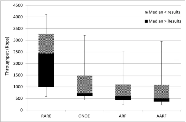
Figure 4-4: Throughput average of 3 nodes transmitting simultaneously. ... 67
Figure 4-5: Throughput average of 10 nodes transmitting simultaneously... 68
Figure 4-6: Throughput average of 13 nodes transmitting simultaneously... 68
Figure 4-7: Throughput average of 15 nodes transmitting simultaneously... 69
VIII
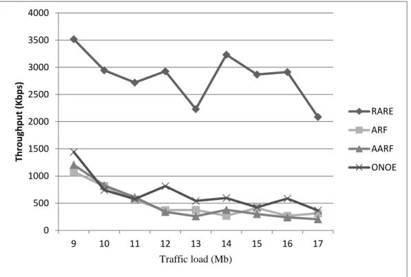
Figure 4-9: Average throughput for network with 9 different loads. ... 70
Figure 5-1: Heterogeneous mesh network. ... 73
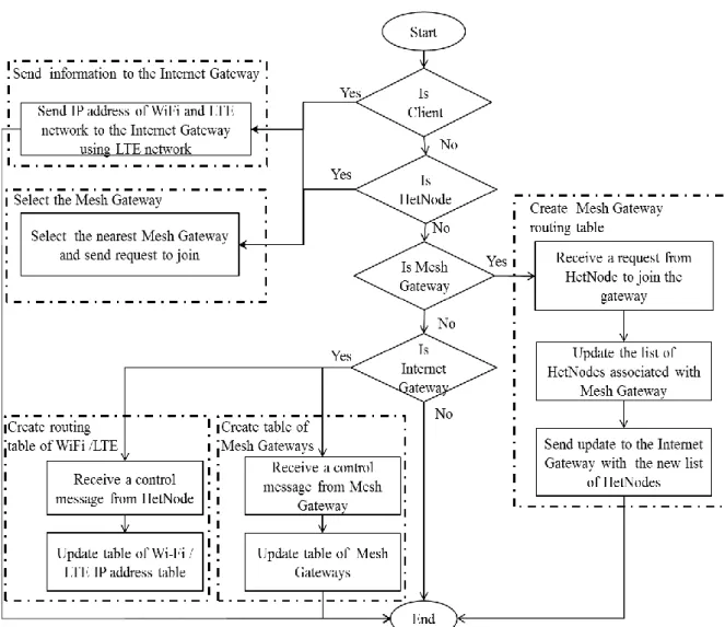
Figure 5-2: Flowchart of creating routing tables. ... 77
Figure 5-3: Flowchart of CHR routing algorithm. ... 82
Figure 5-4: Uplink grid scenario with 19 nodes. ... 89
Figure 5-5: Uplink random scenario with 19 nodes. ... 89
Figure 5-6: Uplink grid scenario with 30 nodes. ... 90
Figure 5-7: Uplink random scenario with 30 nodes. ... 90
Figure 5-8: Different amount of load during the simulation on uplink. ... 91
Figure 5-9: Downlink grid scenario with 19 nodes. ... 91
Figure 5-10: Downlink random scenario with 19 nodes. ... 92
Figure 5-11: Downlink grid scenario with 30 nodes. ... 92
Figure 5-12: Downlink random scenario with 30 nodes. ... 93
Figure 5-13: Different amount of load during the simulation on downlink. ... 93
Figure 5-14: HetMeshNet performance with different value of α in grid scenario (0 ≤ α ≤ 1). ... 94
Figure 5-15: HetMeshNet performance with different value of α using different amount of load during the simulation (0 ≤ α ≤1). ... 94
Figure 5-16: Average network throughput over time with different number of transmission nodes. ... 95
Figure 5-17: Average network throughput with constant number of nodes and mobility. ... 95
Figure 5-18: Number of transmitting packets for each wireless technology. ... 99
Figure 6-1: VANET heterogeneous network scenario. ... 103
IX Figure 6-3: LTE load membership function (in %). ... 109 Figure 6-4: CQI membership function (in db). ... 109 Figure 6-5: Wi-Fi transmission rate membership function (in rate index value). ... 110 Figure 6-6: The success rate for Wi-Fi device (SRW) membership function (in %). .. 110 Figure 6-7: Graph of knowledge base instance for NetNode. ... 113 Figure 6-8: FuzzOnto reasoning flowchart ... 120 Figure 6-9: Average throughput for urban heterogeneous network with low load. ... 124 Figure 6-10: Average throughput for urban heterogeneous network with medium load. ... 124 Figure 6-11: Average throughput for urban heterogeneous network with high load. .. 125 Figure 6-12: Packet delivery fraction of urban heterogeneous network with low load.125 Figure 6-13: Packet delivery fraction of urban heterogeneous network with medium load. ... 126 Figure 6-14: Packet delivery fraction of urban heterogeneous network with high load. ... 126 Figure 6-15: Average throughput for VANET heterogeneous network with low load. 128 Figure 6-16: Average throughput for VANET heterogeneous network with medium load. ... 129 Figure 6-17: Average throughput for VANET heterogeneous network with high load. 129 Figure 6-18: Packet delivery fraction for VANET heterogeneous network with low load. ... 130 Figure 6-19: Packet delivery fraction for VANET heterogeneous network with medium load... 130 Figure 6-20: Packet delivery fraction for VANET heterogeneous network with high load. ... 131
X
List of Tables
Table 4-1: Simulation setup. ... 62
Table 4-2: ANOVA test results. ... 66
Table 4-3: LCD test results. ... 66
Table 5-1: Simulation setup. ... 86
Table 5-2: ANOVA test results. ... 97
Table 5-3: LSD test results. ... 98
Table 6-1: Ontology classes. ... 106
Table 6-2: Ontology properties. ... 106
Table 6-3: ANOVA test results. ... 131
XI
List of Abbreviations
3GPP 3rd Generation Partnership Project AARF Adaptive auto rate fall-back
AHP Analytic hierarchy process AI Artificial intelligence
AMARF Adaptive multi-rate auto rate fall-back ANOVA An Analysis of variance
AODV Ad-hoc on-demand distance vector API Application program interface ARF Auto rate fall-back
CARA Collision-aware rate adaptation CBR Constant bit rate
CCH Control channel
CSC Channel switching cost
CSMA/CA Carrier-sense multiple access with collision avoidance
XII CCTAE Computer and Communication Technologies in Agriculture Engineering CHR Cognitive heterogeneous routing
CQI Channel quality index
DCF Distributed coordination function
DREAM Distance routing effect algorithm for mobility DSDV Destination-sequenced distance vector DSR Dynamic source routing
DSRC Dedicated short range communication eNB/eNodeB Evolved node b
EPC Evolved packet core
ETT Expected transmission time ETX Expected transmission count GPS Global positioning system GUI Graphical user interface IoT Internet of Thing
XIII IRU Interference aware resource usage
ISM Industrial, scientific and medical LCD Link connectivity duration LSD Least significant difference LTE Long term evolution
MCS Modulation and coding scheme MDPU MAC protocol data unit
MIC Interference and channel switching metric MIH Media independent handover
MIMO Multiple in and multiple out MME Mobility management entity MutFed Mutual-feedback rate adaptation NP Non-deterministic polynomial-time OLSR Optimised link state routing OWL Ontology web language
XIV QoS Quality of service
RAN Radio access network
RARE Rate adaptation algorithm based on reinforcement
RB Resource block
RDF Resource description framework
REFOT Relative fairness and optimised throughput RLC Radio link control
RERR Route error
RREP Route response
RREQ Route request
RTS Request to send
S-GW Serving gateway
SCH Service channel
SINR Signal-to-interference-to-noise ratio TA-ARA Traffic-aware active link rate adaptation TARA Throughput-aware rate adaptation
XV UDP User datagram protocol
UE User equipment
VANET Vehicular ad-hoc network V2I Vehicle to infrastructure V2V Vehicle to vehicle
WAVE Wireless access in vehicular environments WMN Wireless mesh network
WSN Wireless sensor networks WSW Weight to select the Wi-Fi
XVI
List of Notations
Variable Variable description
Φ A set of all available nodes in the network, d ϵ Φ
α Learning rate of reinforcement learning
BufLd(t
i) Number of packets in the LTE transmission buffer for node d ϵ Φ at time ti
BufLmax Maximum number of packets that the transmission buffer of LTE device
can accept
CQWd(t
i) Wi-Fi channel quality for node d ϵ Φ at time ti d A heterogeneous network node
Exp Boolean variable indicating whether the algorithm is in exploration mode
Expcount Number of exploration cycles completed
expThr Maximum number of explorations allowed
F Number of consecutive transmissions failure on the node
FlagW Boolean variable indicating whether the Wi-Fi device has been used
FLC Fuzzy set of the LTE channel quality
FLL Fuzzy set of the LTE load
FRd(t
i-1, ti) Failure rate of a wireless node d ϵ Φ
FWC Fuzzy set of the Wi-Fi channel transmission rate
FWS Fuzzy set of the Wi-Fi success rate
IQd(t
i) Instantaneous queue length of node d ϵ Φ
LCDi,j Lifetime of communication link between nodes i and j LCDth LCDthreshold value (in this work, 30 s is used) LLd(t
XVII
LPd(ti-1, ti) Probability of accessing the shared channel for node d ϵ Φ LQd(ti-1,,ti) Link quality of node d ϵ Φ
LSW LTE strength weight
LTELd
t LTE device load for node d ϵ Φ at time t MaxQL The physical maximum queue length
MaxQthr Maximum queue threshold
MDPU MAC protocol data unit
MinQthr Minimum queue threshold
MissedPkt Number of unsuccessful transmissions till current time (ti) R(ti) Reward at time ti
Rated Current data rate of node d ϵ Φ
RAND RAN decision
RBd
t Number of allocated resource blocks for node d ϵ Φ at time t RBMax Number of available resource blocks of the LTE cell
RWd(ti) Transmission rate for node d ϵ Φ in the Wi-Fi device at time ti
RWmax Maximum transmission rate that the Wi-Fi transmission technology can
support
S Number of consecutive transmissions successful
SendData Total number of transmission till current time (ti)
SRLd(ti-1-ti) Success rate of node d ϵ Φ to access the LTE network since the last
update of the probability to access LTE channel
SRWd(ti-1 -ti)
Success rate of node d ϵ Φ to access the Wi-Fi network since the last update of the probability to access Wi-Fi channel
STLd(ti-1-ti) Number of successful transmissions on the LTE device for node d ϵ Φ
since the last update of the probability to access LTE channel
STWd(t i-1 -ti)
Number of successful transmissions on the Wi-Fi device for node dϵ Φ
XVIII
ti Represent the current time instance ti-1 Represent the previous time instance of ti TTLd(t
i-1-ti) Total number of transmissions using the LTE for noded ϵ Φ since the last
update of the probability to access LTE channel
TTWd(t i-1 -ti)
Total number of transmissions using the Wi-Fifor noded ϵ Φ since the last update of the probability to access Wi-Fi channel
Qd(t
i) Statues of wireless channel for node d ϵ Φ QLd(t
i) Probability of accessing the LTE channel for node d ϵ Φ at time ti Qlend Average queue length of node d ϵ Φ
QWd(t
i) Probability of accessing the Wi-Fi channel for node d ϵ Φ at time ti V A set of nodes that share the communication channel, j ϵ V
XIX
List of Publications
Journal articles:
Ahmed Al-Saadi, Rossi Setchi, and Yulia Hicks and Stuart Allen, “Routing Protocol for the Next Generation of Heterogeneous Wireless Mesh Networks,” IEEE Transactions on Vehicular Technology, Issue: 99, pp 1-15, 2016.
Ahmed Al-Saadi, Rossi Setchi, Yulia Hicks, “Semantic Reasoning in Cognitive Networks for Heterogeneous Wireless Mesh Systems”, Submitted to IEEE Transactions on Cognitive Communication and network.
Conference proceedings:
Ahmed Al-Saadi, Rossi Setchi, Yulia Hicks and Stuart Allen, “Multi-Rate Medium Access Protocol Based on Reinforcement Learning”, IEEE SMC, pp 2875 – 2880, San Diego, USA, 2014.
Ahmed Al-Saadi, Rossi Setchi, Yulia Hicks, “Cognitive network framework for heterogeneous wireless networks”, Procedia Computer Science, vol. 60, pp 216–225, Singapore, 2015.
1
Introduction
Introduction to Communication Networks
Communication networks can be categorised based on whether the transmission medium is a wired or wireless network. The wired network connects devices to other networks using cables; one of the most well-known example of this type is the local area network that known as the Ethernet. The wireless network is defined as a network that uses radio frequency bands to connect devices such as smartphones to the Internet or to a private business network. The frequency bands in telecommunications are defined as a specific range of frequencies in the radio spectrum. Because the simultaneous use of the same frequency band can cause interference and result in data loss, frequency usage is regulated by the International Telecommunication Union (ITU).
Among many of the successfully deployed wireless networks, cellular and multi-hop Wi-Fi-based networks are two of the most promising technologies. cellular network is led by ITU and the 3rd Generation Partnership Project (3GPP), which focuses on delivering
2 high quality services to mobile users. The other is led by the Institute of Electrical and Electronics Engineers (IEEE), which emphasises the ease of access to the network. Cellular networks include a set of terrain areas called cells, each of which is served by at least one fixed base station (BS). Each cell uses different frequency bands to avoid interference and guarantee the bandwidth. A cellular network provides large coverage to fixed and mobile devices, such as mobile phones, laptops, tablets, etc. The concept of cellular networks follows gradual trends, which started with the first generation (1G) and led to the current fourth generation (4G). Long-term evolution advanced (LTE-A) (3GPP TS 36.211 V8.7.0 2009) is considered the real 4G network. LTE-A was standardised by 3GPP and approved by the ITU. LTE-A networks consist of two main parts: the LTE base station, or evolved Node B (eNodeB or eNB) base station, and the evolved packet core (EPC). The eNB provides cell coverage, radio resource management and connection mobility management. The purpose of the EPC, which was first introduced by 3GPP in Release 8 of the standard, is to handle the network data traffic efficiently from the perspective of cost and performance.
Multi-hop wireless networks employ Wi-Fi to establish a network without a centralised infrastructure. The data unit, which is known as a packet, is transmitted by forwarding data from one node to another until they reach their destination; each node represents one hop count. A wireless mesh network (WMN) is a multi-hop wireless network that establishes a metropolitan area network. The WMN consists of three types of nodes: gateway, mesh and client. The gateway node has a high-speed wired connection to the Internet; mesh nodes are used as relay nodes to propagate data to and from the gateway; client nodes are devices that seek a connection to the Internet, such as mobile devices, laptops, etc. The packets are transmitted from one mesh node to another until
3 they reach the gateway. In WMN, routing algorithms are developed to calculate the path for transmitting data from the source to the destination that optimises the network’s performance.
Another important part of computer networks comprises the communication protocols, which use a set of rules to enable computer-based devices to communicate with each other. These protocols work as a set of network layers that are known as a network protocol stack to enable network capabilities. The protocols at each layer are mutually agreed on the format of performing functions. Figure 1.1 shows a block diagram of two nodes that use the transport control protocol / internet protocol (TCP/IP) network layers to communicate with each other. The application layer handles the details of the particular application. The hypertext transfer protocol (HTTP) and file transfer protocol (FTP) are examples of application layer protocols. The transport layer provides the end-to-end data transfer by delivering data from one application to its remote peer. The most frequently used transport layer protocol is TCP. The network layer, also known as the Internet layer, is responsible for routing data packets and forming the network; it shields the upper layer from the physical network. The Internet protocol (IP) is the most important protocol in this layer. The last layer is the physical layer, which is the actual interface with the physical hardware that is responsible for sending data through the network.
4 Figure 1-1: TCP/IP network layers
Motivation
Over the next three years, Internet traffic is expected to increase three to five times because of the growing number of connected mobile devices. Within the next decade, a more advanced Internet infrastructure will be required to support this increase in Internet traffic (Huawei 2014).
Next-generation wireless networks must overcome several challenges, including the cost to cover high-density areas, crowded events and large areas and to respond to temporary fluctuations in demand, for example, at a large sporting event. The cost estimation depends on the number of required base stations and the cost to rent frequency bands. Interoperability is another challenge as many devices use different operating systems, protocols and access technologies. Network reliability is also an
5 important issue that needs to be addressed to ensure that systems are able to tolerate faults or interruption to the service in case of disasters (IWPC 2014).
The use of heterogeneous technologies, such as cellular and Wi-Fi networks improves the overall network performance by distributing the load across different network technologies (Hu et al. 2012; Yang et al. 2013; Hagos and Kapitza 2013), which provides an opportunity for higher network capacity, wider coverage and higher quality of service (QoS). However, the process of developing heterogeneous wireless networks is a very challenging task because each network type uses a different radio access network (RAN), has different standards and depends on various QoS parameters. Furthermore, routing packets through a heterogeneous network requires a new mechanism to exchange control messages among the different networks. The design of heterogeneous systems is highly complex because of the diversity of associated devices and resources, as well as the dynamic form of the network (Liu et al. 2013).
The internetworking of different wireless technologies, particularly the LTE network and the IEEE 802.11-based wireless mesh network (WMN), is one of the key opportunities involved in developing the next-generation wireless networks. The use of a WMN increases the network capacity by utilising unlicensed frequency bands, which reduce the cost of buying more LTE licensed frequency. The LTE network is used to avoid low-quality Wi-Fi links and it can connect island nodes if a link failure occurs.
LTE networks provide wide coverage and a peak transmission rate ranging from 100– 326.4 Mbps on the downlink (from base station to user equipment) and 50–86.4 Mbps on the uplink (from user equipment to base station) depending on the antenna configuration and modulation depth. Due to the advanced technologies employed in the LTE networks, they can be used by major mobile operators around the world to cope
6 with the high traffic demands. However, LTE networks use licensed frequency bands, which means that costs are incurred to provide more bandwidths through buying more frequency bands (which may not be available in all regions) or through investing in a higher density of base stations.
The WMN is a paradigm that was developed to provide wide network coverage without using the centralised infrastructure (Akyildiz et al. 2005). Therefore, WMNs are a feasible choice to provide a backbone network for metropolitan area networks (MANs). Gateways, which are wireless nodes that have a high-speed wired connection to the external Internet, are used to connect the WMN to the Internet. This architecture offers a cost-effective, ubiquitous wireless connection to the Internet in large areas through multi-hop transmissions to and from the gateway. However, the major drawbacks of using WMNs are their limitations in terms of capacity, system performance and guaranteed wireless link quality. The causes of these limitations originate from the multi-hop nature of the network. When data packets traverse a greater number of multi-hops in a large WMN, either they can fail to reach their destination or they consume too many network resources. Moreover, in the case of a link or node failure, some nodes become isolated from the network because of the lack of a path to the destination or gateway, and form an island node.
One possible way to simplify the complexity of heterogeneous wireless networks is to employ cognitive networks. A cognitive network utilises network characteristics as input and extends network services by developing reasoning mechanisms for simplifying the complexity of managing modern wireless networks and enhancing network performance (Thomas 2007). The general issue with cognitive networks is finding the actions that move the network from a current situation to a desired situation, which tends to be a
non-7 deterministic polynomial-time (NP) hard problem (Facchini 2011). The problem that the cognitive network model faces in heterogeneous WMNs is challenging because of the need to secure the QoS characteristics of multiple network architectures and to find the optimal solution using reasoning mechanisms.
The use of semantic technologies as a part of the cognitive network could establish a method to describe, annotate and create relationships of various QoS parameters and network characteristics. The integration of different artificial intelligence (AI) algorithms in the reasoning system would allow the automatic processing of the network operations, including optimisation, configuration and management. The introduction of AI-based systems in self-organised mobile networks offers an effective way toward developing smart future mobile networks (Wang et al. 2015).The use of a semantic based system enables each node in the heterogeneous network to be self-configured and aware of the surrounding environment and any additionally installed transmission devices.
Aim and Objectives
The aim of this research is to develop a novel heterogeneous wireless mesh networks architecture based on using LTE and WMN to improve the overall network capacity, link quality and coverage. This is achieved by developing a smart system for configuring, optimising and managing heterogeneous wireless mesh networks autonomously and facilitating the process of extending this network automatically. The project aims to build a framework that models the various network architectures using semantic based system and establishes a technique to develop reasoning systems using AI algorithms.
8
Creation of a cognitive network framework based on a semantic system to optimise, configure and manage heterogeneous wireless mesh network.
Building a rate adaptation technique for WMN to mitigate the impact of interference.
Creation of routing metric based on the transmission rate that reflects the quality of the shared transmission channel.
Building a novel heterogeneous wireless mesh network architecture of WMN and LTE that overcomes the drawbacks of each transmission technology utilised in the network.
Development and validation of a new heterogeneous wireless mesh routing protocol that prescribes the required control messages and routing tables to enable the communication of heterogeneous transmission devices.
Development of a new route selection algorithm to select transmission device to optimise the heterogeneous network performance.
Development of a new semantic knowledge base system that simplifies the process of capturing the parameters of the heterogeneous systems from different layers of the network protocol stack through the use of ontologies and semantic rules.
Establishing a semantic inference engine to configure different communication systems automatically and optimise the network performance without a need to customise the software of the transmission device or update other layers of the Internet protocol stack.
Thesis Outline
9 Chapter 1 has provided an introduction to the work.
Chapter 2 has introduced a state of the art review of wireless network architectures and discusses related work in the field. It also reviews the relevant literature in the area of rate adaptation algorithms in wireless local network, the related work in the scope of heterogeneous wireless networks, reinforcement learning and fuzzy inference, semantic web and ontologies.
Chapter 3 has proposed a cognitive network framework for optimising, configuring, and managing the heterogeneous wireless mesh network.
Chapter 4 has introduced a new rate adaptation algorithm for wireless mesh networks. Chapter 5 has proposed a novel heterogeneous wireless mesh network architecture that utilises WMN and LTE networks; it also has introduced a new heterogeneous routing protocol and routing selection algorithm based on reinforcement learning.
Chapter 6 has used the developed heterogeneous WMN architecture to define an ontology based system to model and represent the heterogeneous wireless mesh network and also developed a reasoning system based on fuzzy controller to facilitate the process of configuring and optimising other wireless network architectures.
Chapter 7 highlights the contributions, limitations, and conclusions of this thesis, and proposes further work.
10
Literature Review
This chapter reviews the state of the art in the research areas relevant to the work presented in this thesis. Initially, the wireless technologies and network architectures utilised in this research are discussed with detailed examples in Section 2.1. Section 2.2 highlights the existing work on WMNs; section 2.3 examines the rate adaptation algorithms in wireless local network; section 2.4 discusses the related work in the scope of heterogeneous wireless networks. Section 2.5 discusses the cognitive network, which is followed by a review about employing semantic web and ontologies for wireless networks in section 2.6. Then the reviews of the concepts related to reinforcement learning and fuzzy interference are presented in section 2.7 and 2.8 respectively. Finally, Section 2.9 summarises the findings and concludes the Chapter.
Wireless Networks
This section introduces the communication systems that this research utilises to create the proposed heterogeneous network architectures.
11
IEEE 802.11 Wireless LANs
IEEE 802.11 is a set of standards that was developed by IEEE standard committee (802) (Std, IEEE Committee 1990). The IEEE 802.11 standard defines a medium access control (MAC) layer and multiple physical layer specifications. The MAC defines the addressing and channel access mechanisms to make it possible for several network nodes to communicate with each other. The MAC layer acts as an interface between the physical layer that is responsible to set frequency bands, transmission power and the upper layers. The channel access mechanism in IEEE MAC is based on carrier-sense multiple access with collision avoidance (CSMA/CA) and a distributed coordination function (DCF). The transmission medium is shared among multiple nodes. CSMA/CA is used to prevent collisions before they occur. When the station has a packet to be sent, it checks the transmission medium. If the link is busy, it defers the transmission for a random period and then checks the link again. The DCF function specifies a random waiting time for each node, and then the node transmits a request to send message (RTS), and if it is cleared to send (CTS) the node transmits its packet. This approach minimises the possibility that more than one node checks the channel simultaneously. IEEE 802.11, commonly known as Wi-Fi, provides low-cost, convenient and high transmitting speed technology. It has already been deployed in many hotspots, including airports, libraries, coffee houses and hotels. Wi-Fi uses unlicensed frequency bands, which means it is not necessary to pay for bandwidth; however, this attribute also increases the possibility of interfering with other neighbouring networks. Wi-Fi provides good indoor coverage. Moreover, the chipset price of Wi-Fi is dropping continuously, making it an economical networking option that is included in an increasing number of devices. Wi-Fi offers a data rate up to 780 Mbps in the IEEE 802.11ac, and the bandwidth
12 is device-to-device transmission, which means that all the available bandwidth is allocated to the Wi-Fi node to transmit the incoming traffic. For example, if the available bandwidth for a Wi-Fi node is 54 Mbps, then the Wi-Fi node will utilise the entire bandwidth during the transmission without sharing it with neighbouring nodes.
IEEE 802.11 defines a number of different physical layer technologies. The first version operates in 2.4 GHz industrial, scientific and medical (ISM) bands and achieves 1 and 2 Mbps transmission. Several extensions were developed to provide a higher rate. The following are examples of the most common IEEE 802.11 extensions:
IEEE 802.11b (IEEE Std 802.11b 1999) operates in a 2.4 GHz ISM band and achieves up to 11 Mbps.
IEEE 802.11a (IEEE Std 802.11a 1999) operates in a 5 GHz ISM band with a data rate up to 54 Mbps.
IEEE 802.11g (IEEE Std 802.11g 2003) achieves up to 54 Mbps in a 2.4 GHz ISM band.
IEEE 802.11n operates at 2.4 and 5 GHz and increase transmission rate to more than 100 Mbps.
IEEE 802.11ac (IEEE Std 802.11ac 2013) was developed based on the IEEE 802.11n to provide very high throughput that reaches 1 Gbps and is operated at frequencies lower than 6GHz.
Another approved standard is IEEE 802.11p, which adds wireless access in vehicular environments (WAVE) (IEEE Std 802.11p 2010). The standard is intended to support wireless access in vehicular ad hoc networks (VANETs), which exchange and broadcast safety-related service application data between moving vehicles, vehicle-to-vehicle
13 (V2V) units, or to roadside units, which is known as vehicle-to-infrastructure (V2I) communication. IEEE 802.11p operates in a dedicated short-range communication (DSRC) band of 5.85–5.92 GHz. In this band, one control channel (CCH) is used to transmit safety and control information, while up to six other service channels (SCH) are employed to exchange service information (IEEE Vehicular Technology Society 2006). Each vehicle periodically sends short messages (beacon) over CCH. Beacon signals are employed to announce the presence of the node to the neighbouring nodes and to provide the location and speed information. Figure 2.1 shows an example of a VANET multi-hop network.
Figure 2-1: VANET network example
Long-term Evolution (LTE)
LTE (3GPP TS 36.211 V8.7.0 2009) was evolved from the 3G standard to improve the architecture of 3G cellular standards, such as UMTS and HSPA. It provides wide coverage and a peak transmission rate ranging from 100 to 326.4 Mbps on the downlink (from the base station to user equipment) and 50 to 86.4 Mbps on the uplink (from the user equipment to base station), depending on antenna configuration and modulation
14 depth. The initial release (Release 8) was finished in 2007; currently, 4G is used to refer to this network.
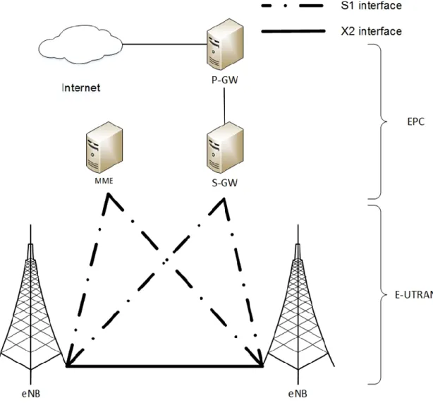
The LTE network architecture involves an Internet protocol (IP) network architecture to provide low latency networks. The LTE network consists of two main parts: the evolved Node B (eNodeB /eNB) base station, which provides the cell coverage; and the evolved packet core (EPC), which connects the network to the Internet. Figure 2.2 shows a comprehensive illustration of the LTE network architecture. The EPC consists of three nodes: the protocol data network gateway (P-GW), the serving gateway (S-GW) and the mobility management entity (MME). The P-GW is the gateway to external IP networks, such as the Internet. The S-GW connects and routes the packets between the user equipment (UE). The MME is the signalling system that handles the node’s mobility and security in the Internet (Amate 2014).
The bandwidth in the LTE network is represented by the total number of resource blocks (RB) that are available for the user equipment in the network. The basic unit in each RB is the resource element (RE). RE represents one symbol by one subcarrier, which usually carries two, four or six physical channel bits, depending on the utilised modulation scheme. Each UE could allocate more than one RB based on the available bandwidth of the LTE network.
Because of the advanced technologies employed in LTE networks, they are used by major mobile operators around the world to cope with high traffic demands. However, because LTE networks operate licensed frequency bands, to provide greater bandwidth, an additional cost is introduced to buy additional frequency bands (which may not be available in all regions) or to invest in a higher density of base stations.
15
Figure 2-2: LTE network architecture (Firmin and 3GPP MCC 2014)
Wireless Mesh Network
The WMN paradigm was developed to provide broad network coverage without using a centralised infrastructure (Akyildiz et al. 2005). In such networks, nodes are used as relays to propagate data from the source to the destination using multi-hop paths to provide service to users. A mesh node can obtain Internet connectivity through a multi-hop path from a mesh gateway, which results in congestion at both the gateway and the nodes close to the gateway.
16 The mesh network provides an appropriate choice to create the infrastructure for metropolitan area networks (MAN). WMNs typically employ IEEE 802.11 to provide an economical approach to indoor and outdoor broadband wireless networks. This network architecture has been deployed in many cities and rural areas worldwide, such as New Orleans, Seattle, Ghana and Zambia (Zhao 2011). Figure 2.3 shows an example of WMN architecture.
Routing protocols and routing metrics have a significant impact on the performance of WMNs. Therefore, this section discusses related works on different routing protocols and metrics in WMNs.
17
Routing Protocols in WMNs
There are two types of routing protocols in WMNs. The first type consists of reactive routing protocols in which the route is created on demand by flooding the network with route requests. The route selection is maintained only for nodes that transmit traffic to a particular destination. Examples of this type of routing are ad hoc on-demand distance vector (AODV) (Perkins et al. 1999) and dynamic source routing (DSR) (Johnson et al. 2001). Reactive routing causes some delays because a route is created only when there are data ready to be sent. Three types of packets are employed in reactive routing, which use the following:
Route request packet (RREQ) floods the network when a node has data packets that need to be sent.
Route response packet (RREP) is unicasted to the originator node that contains the full path to the destination.
Route error packet (RERR) is sent when a route to the destination fails.
The second type of routing protocol consists of proactive or table-driven routing protocols. They maintain a table of the entire destination in the network by periodically distributing an update of the routing table to all nodes. Destination-sequenced distance vector (DSDV) (Perkins and Bhagwat 1994) and optimised link state routing (OLSR) (Jacquet et al. 2001) are examples of this type of routing protocol. The route table maintains the route to each destination; transmission begins with no delay if packets are ready to be sent. However, some overhead is added to distribute routing table information among the nodes in the network. Hybrid routing protocols combine reactive and proactive routing to reduce the overhead of route discovery by employing proactive routing to nearby nodes and generating routes to distant nodes by using on-demand
18 routing (Abolhasan et al. 2003). The zone routing protocol (Haas and Pearlman 1983) and distance routing effect algorithm for mobility (DREAM) (Stefano et al. 1998) are examples of hybrid routing protocols.
Routing Metrics in WMNs
The most widely utilised metrics in WMNs routing protocols select the shortest path to the gateway based on the hop count. Many ad hoc routing protocols, such as AODV (Perkins et al. 1999), DSR (Johnson et al. 2001) and OLSR (Jacquet et al. 2001), employ this routing metric to find the shortest path from the source to the destination. This approach considers the minimum number of hops from the sender to the receiver. However, prior research has recognised a shortcoming in hop count metrics in WMNs: the shortest path metric results in a congested path (Mogaibel and Othman 2009). Moreover, a smaller number of hops may lead to a poor-quality link because the metric does not consider QoS parameters such as delay, bandwidth, link quality or transmission rate (Ahmeda and Esseid 2010; Zhao and Al-dubai 2012). Therefore, many researchers have employed quality-aware metrics, which dynamically evaluate link quality characteristics to improve network performance. Some of these metrics employ a link loss ratio to select the path to the gateway. One of the most widely cited measures is the expected transmission count (ETX) (De Couto et al. 2003), which estimates the required number of transmissions for the successful data delivery between two nodes. However, ETX does not consider the bandwidth, the packet size, or the link interference; therefore, the metric does not perform well on a network that has a high transmission rate and a large packet size. The ETX value can be calculated as follows:
19 𝐸𝑇𝑋 = 1
𝑑𝑓 ∗ 𝑑𝑟, (2.1)
where df is the measured probability that a data packet is successfully received by the receiver, and dr is the likelihood of receiving an acknowledgement by the sender. Expected transmission time (ETT) (Draves et al. 2004) enhances ETX by considering the packet size and the link bandwidth in calculating the metric. However, this metric does not consider the load and link interference. Equation (2.2) is used to calculate ETT value:
𝐸𝑇𝑇 = 𝐸𝑇𝑋 ∗𝑆
𝐵, (2.2)
where S is the packet size and B is the available bandwidth. The interference and channel switching (MIC) metric (Yang et al. 2005) was proposed as an alternative to the ETT. MIC is topology-dependent and selects paths with a minimum number of nodes that share the wireless channel. However, MIC fails to indicate whether the interferer node has data to transmit, as the interferer cannot cause interference when there is no transmission. MIC is calculated using the following equation:
𝑀𝐼𝐶(𝑝) = 1
𝑁∗min(𝐸𝑇𝑇)∑𝑙𝑖𝑛𝑘𝑙∈𝑝𝐼𝑅𝑈𝑙+ ∑𝑛𝑜𝑑𝑒𝑖∈𝑝𝐶𝑆𝐶𝑖, (2.3)
where p is a path in the network, IRU is interferenceaware resource usage for link l on the path p, and CSC is the channel switching cost for node i that belongs to path p. Another routing metric is used to estimate the available bandwidth on the network. Bandwidth can be defined as the amount of data that flows through the network (Zhao
20 2011). Determining the available bandwidth on IEEE 802.11 medium access control (MAC) is challenging because the channel is shared among the neighbouring nodes, and the surrounding environment changes frequently (Peng et al. 2013). One method that is used to estimate the available bandwidth is to listen passively to the channel in order to determine the busy time and the idle time (Chen and Heinzelman 2005; Ramadhan 2010; Peng et al. 2013). When the channel state changes from idle to busy (i.e., the channel is sending or receiving), the node computes the busy time and the idle time during period T. The available bandwidth is calculated using the following equation:
𝐵(𝑘) = 𝐶𝑟𝑎𝑤(𝑘) ∗𝑇𝑖𝑑𝑙𝑒 𝑇 ,
(2.4)
where B(k) is the estimated available bandwidth, Craw(k) is the physical capacity of channel k, and Tidle is the calculated idle time during time slot T.
Another approach to estimating the available bandwidth is to exchange hello messages among the neighbouring nodes containing information that could be used to determine the available bandwidth on the network (Chen and Heinzelman 2005).
In WMN, gateways are employed to connect the network to the Internet. Gateway selection is one of the major problems in WMN because the majority of the traffic goes through the gateway, which causes congestion at these points. Some routing metrics consider gateway selection in calculating the routing path. An example of this parameter is employing a centralised online gateway selection to provide load balancing on the gateways (Galvez et al. 2012). The calculation of this metric consists of two stages: 1) the hop count metric is employed to measure the path cost to the gateway by setting a threshold for the distance to the gateway, and each node maintains a list of valid
21 gateways; 2) the load on the gateway is computed using a central controller that could be any gateway in the network. The gateways collect network parameters and send them to the controller to perform the gateway selection algorithm. However, the central controller requires a wired network of gateways and the central controller. This wired network results in increasing the complexity of building the infrastructure to connect the gateways, which are usually located too far from each other to provide Internet connections in large areas.
Another key link characteristic is the transmission rate. IEEE 802.11 supports multiple transmission rates; for each rate, there is a different transmission range and a different interference range. Changing the transmission rate could improve the network performance to exploit scarce wireless resources optimally under unstable channel conditions. The rate adaptation algorithms are reviewed in the next section.
Transmission Rates in IEEE 802.11
IEEE 802.11 supports multiple transmission rates; for each rate, there is a different transmission range and a different interference range. The physical layer of IEEE 802.11 employs different modulation and coding techniques, which results in providing multiple transmission rates. By applying a higher transmission rate, the node sends data packets faster, which shortens the necessary transmission time and increases the throughput. However, a higher transmission rate requires a higher signal-to-interference-to-noise ratio (SINR) at the receiver in order to decode the packet successfully due to the utilised modulation scheme. Therefore, employing a higher transmission rate requires higher transmission power to meet the SINR needed on the receiver. In turn, this results in
22 higher interference among other nearby nodes and thus reduces the overall network throughput.
Rate adaptation involves two main tasks: estimation of the channel condition and selection of the most applicable transmission rate. This section reviews existing rate adaptation techniques according to the metrics employed to adjust the transmission rate.
Rate Adaptation Based on Frame Loss Statistics
The first category is based on gathering transmission failure statistics on the sender side to estimate the interference level of the receiver side. If the transmission failure exceeds a given threshold, this means that the channel suffers from high interference, and the transmission rate is reduced.
The earliest rate adaptation of this category is auto rate fall-back (ARF) (Kamerman and Monteban 1997). This mechanism was developed for WaveLan II to enhance the application throughput. Each node starts with the basic rate (2 Mbps) and then sets a timer. If either the timer expires or N (a given threshold) consecutive successful transmissions take place, the node increases the transmission rate and resets the timer. If the new rate fails directly, or if there are two consecutive fails, the node decreases the rate.
Recent work in this area has proposed improving the performance of ARF by avoiding updating the transmission rate when the cause of transmission failure is not due to interference. Adaptive ARF (AARF) (Lacage et al. 2004) improves ARF by changing the threshold for switching the data rate adaptively. ONOE (MADWIFI, 2013) assigns credits to the rates based on the network statistics and selects a transmission rate with a loss
23 ratio of less than 50%. Collision-aware rate adaptation (CARA) (Kim et al. 2006) enables requests to send/clear to send (RTS/CTS) handshaking messages of distributed coordination function (DCF) only when the number of transmission failures exceeds a certain threshold. Adaptive multi-rate ARF (AMARF) (Xi et al. 2006) assigns different success threshold for each data rate and uses these numbers as a criterion to switch the transmission rate.
The limitation of all these approaches of rate adaptation is that they do not distinguish between channel error and packet collision when there is a transmission failure. Moreover, these techniques do not take into account the competing nodes accessing shared channels in WMN and the congestion in those nodes.
Rate Adaptation Based on Traffic Estimation
These types of rate adaptation algorithms consider the traffic at the sending node and whether the current transmission rate can meet the traffic demand. Traffic-aware active link rate adaptation (TA-ARA) (Ao et al. 2010) and the method proposed in (Du et al. 2013) estimate the load on nodes by measuring the buffer length of each node and update the transmission rate based on the load in the node. The former updates the transmission power with the transmission rate while the latter keeps the transmission power constant. This type of rate adaptation can cause high interference in networks like WMN as it suffers from high congestion, especially in the nodes close to the gateway. Therefore, these approaches increase the transmission rate of nodes with high traffic loads, which results in high interference to the other nodes in the WMN.
24
Throughput-Aware Rate Adaptation
Throughput-aware rate adaptation algorithms predict throughput gain by updating the transmission rate and mitigating the bad impact of interference on the network. Relative fairness and optimised throughput (REFOT) (Benslimane and Rachedi 2014) achieves fairness among nodes in mobile ad hoc networks (MANET) while maintaining network throughput. Throughput-aware rate adaptation (TARA) (Ancillotti et al. 2009) selects the best transmission rate to provide higher throughput through estimating packet transmission times and network activity.
Receiver-Based Rate Adaptation
In receiver-based rate adaptation, the receiver station measures the channel state and sends feedback to the sender node to adjust the transmission rate according to the received feedback. Mutual-feedback rate adaptation (MutFed) (Khan and Mahmud 2010) measures the received signal power on the receiver node and selects the suitable transmission rate. Then, it sends the suggested transmission rate as a feedback to the sender. Upon receiving the feedback message, the transmitter may accept or decline the suggested transmission rate.
Heterogeneous Wireless Networks
This section discusses wireless networks that utilise different types of transmission technologies. The wireless networks are reviewed according to the way of employing heterogeneous transmission technologies in the network.
The first type of heterogeneous network in which the client is capable of using vertical handover. The vertical handover is the process of switching from one network to a
25 different network to avoid congestion, poor channel quality, or to improve the QoS. Media independent handover (MIH) is proposed by the IEEE group (802.21) to provide a seamless vertical handover between different RAN (IEEE 802.21 Working Group 2009). IEEE 802.21 standard provides the link layer and other network information to the upper network layer to improve the handover in the heterogeneous networks. MIH is employed to provide handover between IEEE 802 family of standards, such as Wi-Fi and Wi-Max (Tamijetchelvy et al. 2012; Hamaydeh et al. 2013) or 3GPP network (Chu and Kim 2013). The decision of selecting the transmission technology is a crucial part of vertical handover; some work considers the user preferences as the most important parameter in selecting the network to carry out the communication (Gupta and Rohil 2013). While other algorithms consider QoS parameters in choosing the best network, for example, solving the problem of network congestion (Walid et al. 2014). Vertical handover in ad-hoc networks is another way to utilise different radio technology (such as Wi-Fi, Bluetooth and ZigBee) to improve frequency utilization, reduce interference and increase network capacity (Stuedi and Alonso 2005; Waheed and Karibasappa 2008; Le et al. 2010; Fujiwara et al. 2012).
Other types of heterogeneous networks split data among broadband and Wi-Fi wireless networks to increase network capacity. One approach is to distribute traffic among networks fairly (Yang et al. 2013) by employing load-balancing algorithms. Other architectures employ wireless characteristics to distribute data among networks. For instance, networks with better wall penetration are utilised for indoor communication such as Wi-Fi network while networks with higher frequency bands are employed for outside communication such as LTE or WiMAX (Hu et al. 2012; Hagos and Kapitza 2013). Traffic priority is employed to manage packets flow in heterogeneous networks
26 (Chen et al. 2010) in which only sensitive packets from the Wi-Fi network are forwarded through the cellular network to avoid weak links.
A cellular network is a mobile network that distributed over land areas called cells. A new architecture that combined cellular network with multi-hop Wi-Fi architecture is proposed to relay data packets for clients that suffer from low channel quality, or to offload a congested cell by forwarding the traffic to other non-congested cells (Wu et al. 2001; Li et al. 2002; Luo et al. 2003; Dixit and Yanmaz 2005). These networks utilise the multi-hop Wi-Fi network as an auxiliary network to redirect traffic from one cell to another. IEEE 802.11-based vehicular ad hoc networks (VANETs) and LTE networks are employed to form a hybrid network in which some nodes in VANET are elected to work as a gateway to forward traffic demands to the LTE base stations (Tabbane et al. 2015; Taleb et al. 2015). The access network is selected based on a set of QoS parameters to improve the network performance throughout the mobile path of vehicles.
Other recent research aims to improve cellular networks by employing a mixture of macro cells and small cells, such as microcells, pico-cells, and femto-cells (Pantisano et al. 2012; Zhang 2012; Soh et al. 2013; Palanisamy and Nirmala 2013; Lin and Feng 2014; Soret and Pedersen 2015). The use of small cells improves the frequency reuse by employing lower transmission power, which produces less interference and increases the data rate of cellular networks. Wi-Fi access points are also utilised to create pico-cells to offload congested pico-cells in cellular networks (Himayat et al. 2014).
A promising approach is to equip cellular base stations with different wireless access technologies and frequency bands to reduce the interference between neighbouring cells (Suga and Tafazolli 2013). The coverage of each base station is divided into a number
27 of regions based on the modulation and coding scheme (MCS) utilised by each wireless technology in the base station.
Cognitive Networks
The cognitive network is a network paradigm that was recently developed to reduce network complexity and enhance network performance. Based on the literature, the cognitive networks have the following characteristics:
Extensibility, flexibility, and proactivity;
Their ability to use network metrics as input and produce an action to the network as output;
The ability to improve network performance compared with traditional networks (Facchini 2011).
In cognitive networks, it is difficult to determine the actions that move the network from a current situation to a desired situation, which tends to be a non-deterministic polynomial-time (NP) -hard problem (Facchini 2011). The problem that a cognitive network model faces in heterogeneous WMNs is challenging because of the need to secure the quality of service (QoS) characteristics of multiple network architectures and to find the optimal solution using reasoning mechanisms.
The cognitive network process, which is known as a cognition loop, is represented in Figure 2.4 (Fortuna and Mohorcic 2009). The cognitive loop consists of six modules: Sense, Learn, Plan, Decide, Act and Environments. The network collects, gathers and pre-processes parameters to sense the environment (Sense). The information gathered by the Sense module is further used in planning the network functions (Plan) and then is
28
Figure 2-4: The cognition loop (Facchini 2011)
fed to learning stage (Learn) to aid the decision maker (Decide) in future actions. The planning module determines potential actions, such as selecting next hop in WMN or updating transmission power for the network based on observations. The decision module decides the possible moves based on the available actions and experience learned from previous actions. Then the Act module performs the selected action in the environment. The learning module is well connected with multiple modules (Sense, Plan, Decide and Act), so it can perform reasoning based on the knowledge acquired from different stages in the cognition loop.
Several studies (Thomas et al. 2006; Uchida et al. 2011; Li et al. 2013; Bennis et al. 2013; Lee et al. 2007; Rovcanin et al. 2014) showed examples of how the cognition loop is used to assess the current network conditions, and then to apply learning and artificial intelligence (AI) algorithms to decide future actions. For example, Uchida et al. (2011)
29 proposed a cognitive network for disaster situations in which a transmission device was used as a control device to exchange the network QoS parameters, and then an algorithm was developed based on the analytic hierarchy process (AHP) to select the most suitable link for handling traffic transmission. Other studies used reinforcement algorithms to create a cognitive process to mitigate the impact of interference in wireless networks (Li et al. 2013; Bennis et al. 2013; Rovcanin et al. 2014). For example, reinforcement learning can be employed in macrocells to collaborate and learn from other cells to reduce the power required by a macrocell base station and to enhance the coordination of inter-cell interference (Li et al. 2013; Bennis et al. 2013). Another study used reinforcement algorithms to create cooperation between different networks to avoid interference, such as activating or deactivating some services (Rovcanin et al. 2014).
Semantic Technologies
This part of the review introduces the principles of semantic technologies and ontologies and then discusses the use of these technologies in the wireless communication field, before highlighting the research gap in this area.
Ontology
As defined in (Gruber 1993), ontology is ‘a specification of a representational vocabulary for a shared domain of discourse’. It specifies the formal representation of types, properties and relationships among data in a given domain. Ontologies are used to create relationships between technology-dependent features. Inference engines, or reasoners, utilise the instances of ontologies in a knowledge base to infer the appropriate action to be taken based on a set of predefined rules. The data in the ontology are defined as a set of relationships between resources, whereas the reasoner infers new
30 relationships based on the data and the rules. Figure 2.5 shows an example of using ontology classes and properties to represent network nodes. It shows Net class as the root class that represents the network and Node as a subclass of Net. Wi-Fi is a subclass of Node that has three properties: has_Neighbour, has_Address and has_DataRate. This example shows how ontologies use classes and properties to create relationships between different network components. Reasoning could be used to infer new relationships; for example, the “has_Neighbour” property could be used in a routing protocol to infer the one-hop count away from the node.
Standard ontology languages define a set of classes, subclasses, properties and relationships. The ontology is then employed to create an abstraction model for different classes and properties and create domain knowledge base. The most well-known languages are the resource description framework (RDF) (Klyne and Carroll 2004), RDF
31 schema (Brickley and Guha 2000) and ontology web language (OWL) (McGuinness and Harmelen 2004).
RDF defines a set of assertions, or statements, which consist of three parts: subject, predicate and object. The subject is the thing being described, and the predicate is the relationship between the predicate and the object. RDF provides the ability to describe metadata and how they relate. RDFS defines the schema of the ontology, and it defines classes and properties to build the ontology schema. RDFS semantics (Hayes and Mcbride 2004) introduce some inference capabilities to the documents. OWL is a powerful ontology language that defines classes and different types of properties and allows for reasoning and consistency checking on the ontology. OWL inference (Patel-Schneider et al. 2004) provides powerful inference operations based on classes, subclasses, object and data properties. OWL 2 (W3C OWL Working Group 2012) is the extended version of OWL, and it has been standardised by the W3C group. OWL 2 extended OWL by providing the following features: property chains; richer data types, data ranges; qualified cardinality restrictions; asymmetric, reflexive, and disjoint properties; and enhanced annotation capabilities. OWL 2 is a very expressive computational language and is therefore very difficult to implement (Taylor 2014). OWL can be used to describe web services, and an extension to OWL was developed for the semantic web service (S) (Martin et al. 2004) used to describe web services. OWL-S is a computer-interpretable language that was developed to describe the web service. OWL-S is expected to enable automatic web service discovery, automatic web service invocation, and automatic web service composition and interoperation.
In this study, a light extensible mark-up language (XML) (Bray et al. n.d.) is employed to create the classes, subclasses, data and object properties, domains and ranges. XML is
32 used for two reasons: First, XML is platform independent, which enables the use of the reasoning system proposed in this study on any smartphone, personal computer or computerised object. The second reason is that the ontology proposed in this work is relatively simple and does not need the extent of expressiveness that is provided by other standard ontology languages. XML is a simple, lightweight ontology system that can work on wireless nodes with limited processing resources. Figure 2.6 shows an example of an XML code that represents the ontology classes on a wireless node.
33 The XML file represents the ontology classes and properties using XML tags, such as hasIPAddress property, to represent the IP address of the node class that is equipped with a Wi-Fi device.
Semantic Reasoning
Semantic reasoning consists of sets of facts and rules that infer local consequences. The data in the ontology are defined as a set of relationships between resources. The reasoner infers new relationships based on the data and the rules. Some reasoning systems have been developed to validate the ontology design, check the consistency of the relationships between ontology classes and regenerate these relationships (Horrocks and Voronkov 2006). This type of reasoning has been embedded as a plug-in in ontology designing tools, such as Protégé (Protégé 2003) and OilEd (Bechhofer et al. 2001).
Semantic Technologies for Wireless Networks
This section reviews advanced approaches to employing ontologies and knowledge engineering in wireless networks. It highlights the use of semantic technologies and ontologies in networking and wireless communication.
A number of studies (Kim et al. 2008; Jabeur et al. 2009; Iqbal et al. 2009; Ren and Jiang 2011; Liu and Xiong 2013; Xiong et al. 2014) used ontologies in wireless sensor networks (WSNs) by observing data from sensor nodes and using that data to build the ontology knowledge base. For example, ontologies and semantic reasoning are employed in routing algorithms for WSNs (Jabeur et al. 2009; Xiong et al. 2014) to select the next hop and forward data based on the data observed by sensors. For instance, if a heat sensor
34 observes high temperature, the no