Published online February 20, 2014 (http://www.sciencepublishinggroup.com/j/wcmc) doi: 10.11648/j.wcmc.20140201.12
Performance assessment of a downlink two-layer
spreading encoded COMP MIMO OFDM system
Md. Mainul Islam Mamun
1, Joarder Jafor Sadique
2, *, Shaikh Enayet Ullah
11
Dept. of Applied Physics and Electronic Engineering, Rajshahi University, Rajshahi, Bangladesh
2
Dept. of Electrical and Electronic Engineering (EEE), University of Information Technology and Sciences (UITS), Dhaka, Bangladesh
Email address:
[email protected] (M. I. Mamun), [email protected] (J. J. Sadique), [email protected] (S. E. Ullah)
To cite this article:
Md. Mainul Islam Mamun, Joarder Jafor Sadique, Shaikh Enayet Ullah. Performance Assessment of a Downlink Two-Layer Spreading Encoded COMP MIMO OFDM System. International Journal of Wireless Communications and Mobile Computing. Vol. 2, No. 1, 2014, pp. 11-17. doi: 10.11648/j.wcmc.20140201.12
Abstract:
In this paper, a comprehensive BER performance simulative study has been made on data transmission in a downlink coordinated multipoint wireless communication System. The COMP MIMO OFDM system under investigation implements Turbo and LDPC channel coding, Spatially multiplexing and Space-time block coding (STBC), Doubly Spreading Minimum Mean Square Error (MMSE) and Zero Forcing (ZF) signal detection (Equalizers) schemes under 16PSK and 16QAM digital modulations based on the analysis it is remarkable that the simulated system is highly effective to combat inherent interferences under Rayleigh fading channel and provides robust performance in 16QAM, MMSE channel equalization and spatial multiplexing schemes.Keywords:
Coordinated Multipoint (CoMP) Transmission, LDPC and Turbo Coding, Two-Layer Spreading, Signal Detection Schemes, Bit Error Rate (BER)1. Introduction
With development of physical layer techniques , the data rates of mobile communication services have increased by about 100 times every 6–7 years and it is predicted that in 2020, the required data rate will be as large as 100–1000 times the currently served data rate. The wireless transmission and networking technologies are the essential components of the mobile communication systems. Due to the recent breakthrough in transmission technologies with consideration of constraints of traditional cellular systems in terms of transmit power, complicacy in frequency of handover in high speed mobile environment (350km/h) and cell edge effect for transmission frequencies higher than 2 GHz, cellular communications have entered the era of cooperative communications. In Cooperative communication system, various types of cooperative schemes such as relay, DAS, multicellular coordination, Group Cell, Coordinated Multiple Point transmission and reception (CoMP) are used [1].
Cooperative communications have recently been migrated to one of state-of-the-art features of the 3GPP LTE-Advanced (LTE-A) system. In LTE-Advanced system, single carrier frequency division multiple access
(SC-FDMA) has been adopted in the uplink communication and orthogonal frequency division multiple access (OFDMA) has been adopt in the downlink communication. In such system, base-station (BS) cooperative transmission under CoMP cooperative transmission scheme has been widely recognized as a promising technique to enhance throughput by avoiding intercell interference (ICI), particularly for cell-edge users. In January 2009, CoMP and Cooperative Relay based trial networks have been deployed in the campus of Beijing University of Posts and Telecommunication. [2, 3]
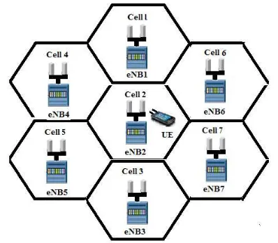
for Handheld terminals (DVB-H), Wireless Local Area Networks (WLANs) and Broadband Radio Access Networks (BRANs). MIMO OFDM is the key technology for various cellular communications such as 3GPP-LTE, Mobile WiMAX and IMT-Advanced. The quality of a wireless link viz. transmission rate, transmission range and transmission reliability can be improved using MIMO aided OFDM technology [4, 5]. In this present study, MIMO-aided OFDM radio interface technology in CoMP transmission based wireless network. In Figure 1, a scenario of joint processing (JP) CoMP transmission based MIMO wireless network has been shown where it is seen that a single mobile user (user equipment, UE) is receiving identical spatially demultiplexed complex signals transmitted simultaneously from seven different geographically located multi antenna supported macro base stations (eNBs).
Figure 1. Downlink Coordinated Multiple-Point Transmission (CoMP) Scenario for homogeneous macro network. User unit (UE) in Cell 2 receives data from seven multi antenna supported macro base stations (eNBs.)
2. Signal Processing Schemes
In this paper, various signal processing schemes have been implemented. A brief overview of such schemes is given below in concise form.
2.1. LDPC Coding and Decoding
An low-density parity-check (LDPC) code invented by Gallager, is a (n,k) linear block code of rate R= k/n . It can be defined in terms of (n-k) × n parity-check matrix [H]=[ h1, h2,
h3 …..hn ]. Each entry hi j of matrix [H] is an element of finite
field of GF(2) viz. 0 or 1. The parity-check matrix contains only a few 1’s in comparison to 0’s (i.e., sparse matrix). In this present study, a ½.-rated irregular LDPC code with code length 1024 has been used. Its parity-check matrix [H] has a dimension of 512 × 1024 and it is formed from a concatenation of two matrices [A] and [P]([H]=[A]|[P]), each has a dimension of 512 × 512. The columns of the parity-check matrix [H]is rearranged/reordered to produce a
new parity-check matrix [Hnew].With reordered matrix
elements, the matrix [A] becomes non-singular and it is further processed to undergo LU decomposition. The redundant or parity bits sequence [p]has been considered to be obtained from the frame based input binary data sequence [u]=[u1u2u3u4…….u512]T and three matrices [P](of
[Hnew]),[L] and [U]using the following Matlab notation :
p = mod(U\(L\z), 2);where, z = mod(P*u , 2);
The LDPC encoded 1024× 1 sized frame based binary data sequence [c] is formulated from concatenation of parity check bit p and information bit u as:
[c]=[p;u] (1)
The first 512 bits of the codeword matrix [c] are the parity bits and the last 512 bits are the information bits. In Log Domain Sum-Product LDPC decoding Algorithm, data retrieval is made with adaptation of an iterative approach. The binary data sequence c is converted into another data sequence x with its each sampled value=+1(-1) when element of c=0 (1).
The received signal vector r (=x+n) is contaminated with the independent white Gaussian noise vector n of variance,
σ2
Initially, four key parametric values are set as follows: (i) A parametric matrix
[
Lci
]
of dimension 1024×1is set as:
2
/
4
]
[
Lci
=
−
r
σ
(2)In row wise iterative decoding, it is assumed that B is a 512× 1024 sized matrix with its each row containing all elements of matrix [LCi], the element wise product of matrix B and modified parity-check matrix [Hnew] is
given by:
[LQIJ]= [Hnew][B] with its element lqij(i=1,2,3…..512;
j=1,2,3 …..1024).
If kki(i=1,2,3….512) is the number of non zero element in
matrix [Hnew] at its different row i.
The [SMIJ] is a 512×1 matrix containing its elements obtained from row wise summation of all non zero elements in matrix [LQIJ]. For each row wise non zero elements in matrix [LQIJ], a new value is computed as:
NWSMim=SMIJi-LQIJim; i=1, 2,….512, m is the
identification number(=1,2,….kk) viz, first, second, third….. non zero element in each row of matrix [LQIJ].
To avoid division by zero/very small value , its threshold value is set at 1×10^-20 which implies that if the computed value of NWSMim is found to be below this level, it would
be threshold value. From values of NWSMim,another
logarithm term is computed as:
IfALIJim containsnon zero elements in each row of matrix
[αij], the previously considered matrix [LRJI] =0512X1024
would be updated through replacing 0’s at the desired locations with
LRJIim=ALIJim×LGSMim (i=1,2,….512), m is the
identification number (=1,2,….kk).
For a matrix [SUMJI] with dimension 1024× 1 with its each element computed from summation of all non-zero elements column wise in matrix [[LRJI], the updated matrix is
[LQi]=[Lci]+[SUMJI] (4)
If element of matrix [LQi] < 0, it indicates 1 and if the element of matrix [LQi] > 0, it indicates 0, the decoded bit sequence b contains merely 1024 binary bits(0/1). Its first 512 bits are the parity and the rest 512 are the retrieved bits [6, 7].
2.2. Turbo Coding and Decoding
Turbo codes are formed by concatenating in parallel two recursive systematic convolutional (RSC) codes separated by an interleaver. The conventional convolutional code is constructed in a feed-forward fashion; that is, the encoder consists of no feedback. In contrast, its RSC equivalence involves feedback in the encoding process. Apparently, the turbo code is a systematic code. Its coding rate is
3 1
, that is, for every input bit, the Turbo encoder produces three code bits. In maximum a posteriori (MAP) turbo decoding, the transmitted message bits can be retrieved iteratively through computation of their log likelihood ratio (LLR).
Let
c
=
c
0,
c
1,
c
2,
c
3...
....
c
N−1 be a codedsequence produced by the rate 1/2 RSC encoder and
1 3
2 1
0
,
,
,
...
....
−=
r
r
r
r
r
Nr
be the noisy receivedsequence where the code word is
c
k=
(
c
k(1)c
k(2))
with the first bit being the message bit and the second bit being the parity bit. The corresponding received word is-
(
(1) (2))
k k
k
r
r
r
=
(5)The coded bit 0/1 is converted to a value +1/-1. The maximum a posteriori (MAP) decoding is carried out as:
) 1 ... 2 , 1 , 0 ( 1 ( 1 ( , 1 1 ( 1 ( , 1 ) 1 ( ) 1 ( ) 1 ( ) 1 ( ) 1 ( − = − = < + = − − = ≥ + = + = N i c c P if c c P if c k k k k k ) r | P ) r | ) r | P ) r | (6) |
A posteriori log likelihood ratio (LLR) of
c
k(1)is givenby
(7)
The MAP decoding rule in Equation (6) can be presented alternatively as:
= ( (1) |r) ) 1 ( k c L sign k
c (8)
The magnitude of LLR, | L(ck(1) |r) | measures the
likelihood of (1) k
c = +1 or ck(1)= −1. The LLR can be
expressed as a function of the probability ( (1) 1|r)
k c
P =+
(
)
( 1 )( 1 )
( 1 )
(1 )
( 1 )
( 1| r )
ln
( 1| r )
( 1| r )
ln
1 ( 1| r )
k k k k k P c L c P c P c P c = + = = − = + = − = + (9)
2.3. Signal Detection Schemes
In Spatially multiplexed MIMO (SM-MIMO) wireless communication system, the transmitted signal Xs, Received signal Y, channel coefficient matrix H and addititive white Gaussian noise term N can be written as the following signal model:
Y=HXs+N (10)
With implementation of Signal Detection/ channel equalization techniques, the transmitted signal is recovered/detected using the following relation:
WY s
X~ detected = (11)
Where, W is the assigned weight matrix for different channel equalization schemes.
In Minimum mean square error (MMSE) channel equalization scheme, the MMSE weight matrix in terms of equivalent channel matrix H and noise variance
σ
n2 is given by- H 1 2 n HMMSE
(
H
H
I
)
H
W
=
+
σ
− (12)In Zero-Forcing (ZF) scheme, the ZF weight matrix is given by [5]-
H H ZF H H H
W =( )−1 (13)
3. System Model
binary data sequence D of length K are channel encoded using
3
1 -rated Turbo coding / ½-rated LDPC. The channel
encoded binary data DFEC is interleaved and mapped into
digitally modulated symbols with its size L depending upon the order of modulation considered and copied. The number of digitally modulated symbols is increased sixty four times in copying section (as the processing gain of the Walsh Hadamard codes is sixty four) and multiplied with Walsh Hadamard (W-H) spreading codes. The spreaded data symbol vector X are spatially demultiplexed/space time block encoded with implementation of Alamouti scheme to produce two complex data streams X1, and X2 .The data of
each stream are rearranged into M(=32*L/(Nc)) number of
blocks. In each block, Nc number of modulated source
symbols, Sm,q(n), n=0,1,2,3……….Nc-1 are
processed with serial to parallel converter (S/P). The time domain signal OFDM signal using inverse Fast Fourier Transform (IFFT) can be written as
1
( 2 )
, ,
0 1
( ) ( )
0
N c
j f tn m q
m q c
n
s
x t S n e
N
t T
π
−
=
=
≤ ≤
∑
(14)
where, m and q are the transmitting antenna and block identifiers ; m=1,2 and q=1,2,3…..M, Ts(=NcTd) is the
OFDM symbol duration, Td is the source symbol duration
and Nc is the total number of sub-carriers(=1024). In each
of the two data stream, the complex data symbols are again multiplied with Walsh Hadamard (W-H) spreading codes after OFDM modulation. However, in each OFDM block, each sub-carrier is used for modulating each source symbol. The subcarrier spacing is assigned to a value of 1/ Ts
and Nc sub-carrier frequencies are located at
1 ...
... 3 , 2 , 1 , 0
,
− =
=
c N n
s T
n n f
(15)
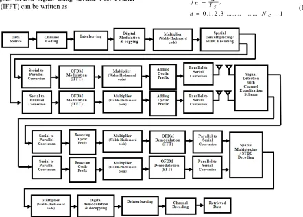
Figure 2. Block diagram of a Downlink Two-Laver Spreading Encoded COMP MIMO OFOM wireless communication system
The sampled sequence of the complex envelope (t
)
(t
)
(t
)
(t
)
xxxxm
,
q
m
,
q
m
,
q
m
,
q
of an OFDM symbol presented in Equation (14) with rate 1/ Td can be written as
1 ... 3 , 2 , 1 , 0
, 1
c N
0 n
c nv/N j2 e ) ( q m, S c N
1 ) ( q m, x
− =
∑−
=
=
c N v
n
v π
(16)
We assume that the OFDM symbol duration Ts is large as
compared to the duration of the impulse response of the channel τmax and ISI is reduced significantly. In order to
avoid completely the effects of ISI and to maintain the
orthogonally between the signals on the sub-carriers for avoiding ICI, a guard interval of duration Tg≥τmax is
inserted between adjacent OFDM symbols. The guard interval is a cyclic extension of each OFDM symbol, which is obtained by extending the duration of an OFDM symbol to
s T g T s
T′ = + (17)
≥
s c max
T N
τ
g
L (18)
The sampled sequence with cyclic extended guard interval results in the following expression [9].
N 1 j2 n v / N
c
1 c
x ( ) S ( ) e
m , q N m , q
n 0
c
v L g ..N c 1
v n π
−
= ∑
=
= − … … … −
(19)
Considering applicability of signal model presented in Equation (19) for all blocks of signals transmitted from all antennas, we can write the transmitted signal vector Xs in terms of its two signal vector components Xs1 and Xs2 as:
1
2
x ( ) x ( ) x (v) x ( )
1,1 1, 2 1, M - 1 1, M
x ( ) x ( ) x (v) x ( )
2,1 2 , 2 2, M - 1 2 , M
X s X s
X s
v v v
v v v
=
=
....
....
(20)
If H1, H2 ...H7are considered to be the 2×2 channel
matrices for the base stations to the user unit and n1,n2 ...n7 are the corresponding zero mean circularly symmetric complex Gaussian noises, Equation (5) can be written under such special case as
Y= (H1+ H2+ H3 +H4+H5+ H6+H7)Xs
+ (n1+ n2+ n3 +n4+n5+ n6+n7) (21)
Equation (21) can be written as in terms of equivalent channel matrix H and Equivalent noise N as signal model presented in Equation (10).
With implementation of channel equalization techniques, the transmitted signals are recovered/detected using signal models presented in Equation (11) through Equation (13)
The detected signals can be represented in matrix form as
= 2 ~1 ~
det ~
s X
s X ected s X
=
) ( M 2, x ~ (v) 1 -M 2, x ~ ) ( 2,2 x ~ ) ( 2,1 x ~
) ( M 1, x ~ (v) 1 -M 1, x ~ ) ( 1,2 x ~ ) ( 1,1 x ~
v v
v
v v
v
....
....
(22)
In Equation (22), first Lg samples of each element of the
two rows are induced with ISI and these Lg samples are
removed from each cyclically extended OFDM block and Walsh Hadamard (W-H) spreading codes prior to multi-carrier demodulation with exploitation of Fast Fourier Transform (FFT). The FFT operated OFDM blocks are undergone parallel to serial conversion and fed into spatial multiplexer/STBC decoder. Its output is multiplied with Walsh-Hadamard codes. The de-spreaded complex symbols are decopied, demodulated, de-interleaved and turbo/LDPC decoded to recover the transmitted data [10,11]
4. Results and Discussion
In this section, we present a series of simulation results to illustrate the significant impact of system performance in
terms of BER in Coordinated Multiple Point transmission and reception. The simulation study has been made using MATLAB 2012a based on the parameters given in Table 1. It is assumed that the channel state information (CSI) is available at the receiver and the fading process is approximately constant during whole transmission time from each macro base station to user unit. The graphical illustrations presented in Figure 3 through Figure 6.
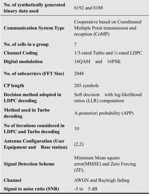
Table 1. Summary of the Simulated Model Parameters
No. of synthetically generated
binary data used 8192 and 8188
Communication System Type
Cooperative based on Coordinated Multiple Point transmission and reception (CoMP)
No. of cells in a group 7
Channel Coding 1/3-rated Turbo and ½-rated LDPC
Digital modulation 16QAM and 16PSK
No. of subcarriers (FFT Size) 2048
CP length 205 symbols
Decision method adopted in LDPC decoding
Soft decision with log-likelihood ratios (LLR) computation
Method used in Turbo
decoding A-posteriori probability (APP)
No of iterations considered in
LDPC and Turbo decoding 10
Antenna Configuration (User Equipment and Base station) (2,2)
Signal Detection Scheme
Minimum Mean square error(MMSE) and Zero Forcing (ZF),
Channel AWGN and Rayleigh fading
Signal to noise ratio (SNR) -5 to 5 dB
receiver, the system performance is well defined and quite satisfactory. At a typically assumed SNR value of -3dB, the estimated BER values are 0.1377 and 0.2802 in case of ZF and MMSE linear equalizer receiver with both 16PSK digital modulations which is indicative of performance improvement by3.09 dB. In Figure 5, Turbo encoded system performances are well defined. At low SNR regime with 16QAM digital modulation, both MMSE and ZF linear equalizer receiver shows almost identical system performance. At SNR value of -3dB, the simulated system is found to have performance improvement of 7.51dB in case of MMSE linear equalizer receiver with 16QAM as compared to ZF linear equalizer receiver with 16PSK. In Figure 5, it is also observable that at a typically target 1%(10-2)BER, the MMSE and ZF linear equalizer with both 16PSK digital modulation require approximately 0.6 dB and 2.9 dB higher SNR respectively as compared to MMSE linear equalizer with 16QAM. On crucial examination of the simulation results presented in Figure 3 through Figure 6, it is observable that the COMP aided simulated system shows comparatively better performance in Turbo channel coding as compared to LDPC. In Figure 6, the turbo encoded simulated system shows robust performance with MMSE linear equalizer receiver and 16QAM and comparatively worst performance with ZF linear equalizer receiver and 16PSK. At -3 dB SNR value, the estimated BER values are 0.0250 and 0.1020 in case of MMSE with 16QAM and ZF with 16PSK which implies a system performance improvement of 6.11 dB. In Figure 6, it is also remarkable that at a typically target 1%BER, the ZF linear equalizer with 16QAM, MMSE linear equalizer with 16PSK and ZF linear equalizer with 16PSK digital modulation require approximately 0.5 dB, 1.1 dB and 1.4 dB higher SNR respectively as compared to MMSE linear equalizer with 16QAM.
Figure 3. BER performance of the system under deployment of LDPC channel coding, Spatial multiplexing various channel equalization and digital modulation schemes.
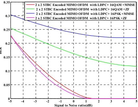
Figure 4. BER performance of the system under deployment of LDPC channel coding, Space-Time Block Coding, various channel equalization and digital modulation schemes
Figure 5. BER performance of the system under deployment of Turbo channel coding, Space-Time Block coding, various channel equalization and digital modulation schemes.
Figure 6. BER performance of the system under deployment of Turbo channel coding, Spatial multiplexing, various channel equalization and digital modulation schemes.
-5 -4 -3 -2 -1 0 1 2 3 4 5
0 0.05 0.1 0.15 0.2 0.25 0.3 0.35 0.4 0.45
Signal to Noise ratio(dB)
B
E
R
2 x 2 Spati all y multipl exed COMP MIMO OFDM with LDPC+ 16QAM +MMSE 2 x 2 Spatially multiplexed COMP MIMO OFDM with LDPC+ 16QAM +ZF 2 x 2 Spatially multiplexed COMP MIMO OFDM with LDPC+ 16PSK +MMSE 2 x 2 Spati all y multipl exed COMP MIMO OFDM with LDPC+ 16PSK +ZF
-5 -4 -3 -2 -1 0 1 2 3 4 5
0 0.05 0.1 0.15 0.2 0.25 0.3 0.35
Signal to Noise ratio(dB)
B
E
R
2 x 2 STBC Encoded MIMO OFDM with LDPC+ 16QAM +MMSE 2 x 2 STBC Encoded MIMO OFDM with LDPC+ 16QAM +ZF 2 x 2 STBC Encoded MIMO OFDM with LDPC+ 16PSK +MMSE 2 x 2 STBC Encoded MIMO OFDM with LDPC+ 16PSK +ZF
-5 -4 -3 -2 -1 0 1 2 3 4 5
0 0.05 0.1 0.15 0.2 0.25 0.3 0.35
Signal to Noise ratio(dB)
B
E
R
2 X 2 Spatially multiplexed COMP MIMO OFDM with Turbo+16QAM+MMSE 2 X 2 Spatially multiplexed COMP MIMO OFDM with Turbo+16QAM+ZF 2 X 2 Spatially multiplexed COMP MIMO OFDM with Turbo+16PSK+MMSE 2 X 2 Spatially multiplexed COMP MIMO OFDM withTurbo +16PSK+ZF
-5 -4 -3 -2 -1 0 1 2 3 4 5
0 0.05 0.1 0.15 0.2 0.25 0.3 0.35
Signal to Noise ratio(dB)
B
E
R
5. Conclusion
In this paper, we have presented simulation results concerning the adaptation of various signals detection and two-layer spreading schemes in a FEC encoded COMP MIMO OFDM wireless communication system. A range of system performance results under the regime of low SNR highlights the impact of Coordinated Multiple Point transmission and reception scheme on data transmission. In the context of system performance, it can be concluded that the spatially multiplexed and Turbo encoded COMP MIMO OFDM wireless communication system with Minimum Mean Square Error (MMSE) signal detection and 16QAM digital modulation schemes provides robust system performance.
References
[1] XiaofengTao ,Qimei Cui XiaodongXu and Ping Zhang “Group Cell Architecture for Cooperative Communications Springer Publisher, New York, 2012
[2] Xiaofeng Tao, XiaodongXu, and Qimei Cui
of Cooperative Communications”, IEEE Communications Magazine, pp.65-71, 2012
[3] Guillaume de la Roche, Andr´esAlay´on Glazunov and Ben Allen: “LTE-advanced and next generation wireless networks channel modelling and propagation”, John Wiley and Sons
Bibliography
Md. Mainul Islam Mamun
as an Assistant Professor
Department of Applied Physics and Electronic Engineering, Faculty of Engineering, University of Rajshahi, Bangladesh. In year 2009 to 2010, worked as a Lecturer in the
of Computer Science and
Telecommunication Engineering Noakhali Science and Technology University, Noakhali, Bangladesh and engaged in teaching Advanced Telecommunications and Computer Science. In 2008, He worked as a Lecturer in the Department of
Engineering, World University of Bangladesh
Bangladesh and taught Advanced Satellite Communication, Communication Engineering, Mechatronics Engineering (Basic and Applied) at undergraduate levels. His
oriented towards simulation study of
Communication Systems (MIMO
LTE-Advanced and Cooperative Relaying).
In this paper, we have presented simulation results concerning the adaptation of various signals detection and layer spreading schemes in a FEC encoded COMP MIMO OFDM wireless communication system. A range of system performance results under the regime of low SNR highlights the impact of Coordinated Multiple Point transmission and reception scheme on data transmission. In the context of system performance, it can be concluded that Turbo encoded COMP MIMO OFDM wireless communication system with Minimum Mean Square Error (MMSE) signal detection and 16QAM digital modulation schemes provides robust
iaodongXu and Ping Zhang: roup Cell Architecture for Cooperative Communications”,
, XiaodongXu, and Qimei Cui: “An Overview , IEEE Communications
´on Glazunov and Ben advanced and next generation wireless networks , John Wiley and Sons
Ltd, United Kingdom, 2013. [4] LajosHanzo, Yosef (Jos) Akhtman ,
“MIMO-OFDM for LTE, Wi and Sons Ltd, United Kingdom, 2011. [5] Yong Soo Cho, Jaekwon Kim, Won
Kang: “MIMO-OFDM Wireless Communications with MATLAB”, John Wiley and Sons (Asia) Pte Limited, Singapore, 2010.
[6] Christian B. Schlegel and Lance C. Perez,
coding”, John Wiley and Sons, Inc., publication, Canada 2004.
[7] BagawanSewuNugroho,
https://sites.google.com/site/bsnugroho/ldpc [8] Yuan Jiang: “A Practical Guide to Error
Using MATLAB”, Jiang Artech House, Boston, USA [9] K. Fazel and S. Kaiser: “Multi
Systems From OFDM and MC
WiMAX”, John Wiley and Sons, Publication Ltd, United Kingdom, 2008.
[10] Goldsmith, Andrea: “Wireless Communications Edition, Cambridge University Pre
2005.
[11] L. J. Cimini, Jr: “Analysis and simulation of a digital mobile channel using orthogonal frequency division multiplexing”, IEEE Transaction on Communication, vol. COM 665–675, 1985.
Md. Mainul Islam Mamun is working
as an Assistant Professor in the Department of Applied Physics and Electronic Engineering, Faculty of Engineering, University of Rajshahi, Bangladesh. In year 2009 to 2010, he worked as a Lecturer in the Department
Computer Science and
Telecommunication Engineering, Noakhali Science and Technology University, Noakhali, Bangladesh and engaged in teaching Advanced Telecommunications and Computer Science. In 2008, He s a Lecturer in the Department of Mechatronics World University of Bangladesh, Dhaka, Advanced Satellite Communication, Communication Engineering, Mechatronics Engineering (Basic and Applied) at undergraduate levels. His research interest is ds simulation study of Advanced Wireless (MIMO-OFDM/OFDMA,
.
Joarder Jafor Sadique
B.Sc. (Hons.) and M.Sc. degree both in Applied Physics and Electronic Engineering
of Rajshahi, Bangladesh in 2010 and 2011 respectively. During his post graduate study, he has completed a research work on MIMO SC Wireless Communication System. His research interest includes Channel Equalization, Radio Interface technologies (OFDMA and SC-FDMA) and Antenna Diversity. Concurrently,
as a Lecturer in the Department of Electrical and Electronic Engineering (EEE), University of Information Technology and Sciences (UITS), Dhaka, Bangladesh.
Shaikh Enayet Ullah
Professor and Chairman of the Department of Applied Physics and Electronic Engineering, Faculty of Engineering, University of Rajsha Bangladesh.
Professor and Chairman (on deputation) in the Department of Information and Communication Engineering, University of Rajshahi. He is working as a member of both Editorial and Reviewer
Journals. He has published more than 70 papers in multidisciplinary fields. His main research interests include Cooperative Communications,
LTE-Advanced and Potential Field geophysical data inversion. , 2013.
LajosHanzo, Yosef (Jos) Akhtman , Li Wang and Ming Jiang:: OFDM for LTE, Wi-Fi and WiMAX,” John Wiley and Sons Ltd, United Kingdom, 2011.
Yong Soo Cho, Jaekwon Kim, Won Young Yang, Chung G. OFDM Wireless Communications with , John Wiley and Sons (Asia) Pte Limited,
chlegel and Lance C. Perez,: “Trellis and turbo , John Wiley and Sons, Inc., publication, Canada,
https://sites.google.com/site/bsnugroho/ldpc
A Practical Guide to Error-Control Coding , Jiang Artech House, Boston, USA, 2010.
Multi-Carrier and Spread Spectrum Systems From OFDM and MC-CDMA to LTE and , John Wiley and Sons, Publication Ltd, United
Wireless Communications”, First Edition, Cambridge University Press, United Kingdom,
Analysis and simulation of a digital mobile channel using orthogonal frequency division multiplexing”, IEEE Transaction on Communication, vol. COM-33, pp.
Joarder Jafor Sadique received his
B.Sc. (Hons.) and M.Sc. degree both in Applied Physics and Electronic Engineering department from University of Rajshahi, Bangladesh in 2010 and 2011 respectively. During his post graduate study, he has completed a research work on MIMO SC-FDMA Wireless Communication System. His research interest includes Channel Equalization, Radio Interface technologies (OFDMA and FDMA) and Antenna Diversity. Concurrently, he is working as a Lecturer in the Department of Electrical and Electronic ng (EEE), University of Information Technology and Sciences (UITS), Dhaka, Bangladesh.
Shaikh Enayet Ullah is working as