Intensification of Transient Stability in Grid
Connected Squirrel Cage Induction Generator
Using Plugging Mode Operation
C.Tamilselvi*1, G.Hemalatha*2, R.Geetha*3, Devika*4
1
PG Scholar, EEE, Coimbatore Institute of Engineering and Technology, India
2,3,4
Assistant Professor/EEE, Coimbatore Institute of Engineering and Technology, India
Abstract: Over the past few decades, there has been an increasing use of induction generator particularly in wind power applications. In generator operation, a prime mover (turbine, engine) drives the rotor above the synchronous speed. Stator flux still induces currents in the rotor, but since the opposing rotor flux cuts the stator coils, active current is produced in stator coils, and motor operates as a generator, and sends power back to the electrical grid. This work investigates a new method for improving the transient stability of power systems equipped with squirrel cage induction generators. For stability improvement, the unique property of the induction machines which is the possibility of reversing the direction of the rotating flux is employed. In this work, after clearing the fault, operating mode of the induction machine is changed from the generating to the plugging mode for a short time. This leads to opposition between the rotating flux and mechanical torques, thus preventing the generator from further acceleration. Simulation results show that the proposed method can be effective in improving the transient stability.
Keywords: Transient Stability, Rotating flux, Plugging mode.
I.INTRODUCTION
Due to the increase of electricity demand and the change of concerning environments, the capacities of renewable energy generation systems, which are mainly connected to a distribution system, are being expanded. The wind-turbine generation system (WTGS) is one of the representative renewable energy systems. Since the WTGS is based on wind energy from natural forces similar to the other renewable energy sources, it does not cause a pollution problem as the conventional fuel such as oil does. Also, it has the main advantage of requiring the lowest maintenance costs.
Wind energy systems are made by fixed-speed induction generators(FSIG), in particular squirrel-cage induction generators (SCIG), which are largely used in power systems because of their
reliability, low cost and robustness. A common problem in wind power plants involves fixed-speed wind turbines. Wind power-plants, being equipped with a squirrel-cage induction generator (SCIG) tend to drain a relevant amount of reactive power from the grid, potentially causing voltage drops and possible voltage instability. Hence, it is necessary to improve the stability characteristics of energy generated from Squirrel-Cage Induction Generator Wind Turbine.
II.NECESSITY OF POWER SYSTEM STABILITY
The power system is a highly nonlinear system that operates in a constantly changing environment(loads, generator outputs and operating parameters) .Hence stability is an important aspect which determines the stable operation of the power system. Power system stability is the ability of an electric power system, for a given initial operating condition, to regain a state of operating equilibrium after being subjected to a physical disturbance, with most of the system variables bounded so that practically the entire system remains intact. The disturbances could be faults, load changes, generator outages, line outages, voltage collapse or some combination of these.
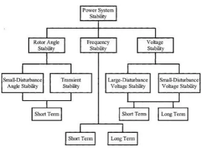
Classification of Power System Stability
Fig. 1 Classification of Power System Stability
1) Rotor Angle Stability:
system to remain in synchronism after being subjected to a disturbance. It depends on the ability to maintain/restore equilibrium between electromagnetic torque and mechanical torque of each synchronous machine in the system. Based on the intensity of the disturbances, it is further classified as small disturbance angle stability and transient stability.
2) Frequency Stability:
It refers to the ability of a power system to maintain steady frequency following a severe disturbance between generation and load. It depends on the ability to restore equilibrium between system generation and load, with minimum loss of load. Frequency instability may lead to sustained frequency swings leading to tripping of generating units or loads. It is moreover classified as short term and long term stability corresponding to the characteristics time of the process.
3) Voltage Stability:
It is the ability of the system to maintain steady state voltages at all the system buses when subjected to a disturbance. Voltage fluctuations occur due to fast acting devices like induction motors, power electronic drive, HVDC etc. It is further classified into large disturbance and small disturbance voltage stability based on the intensity of the disturbances.
III.BRAKING METHODS OF INDUCTION MACHINE
During acceleration, all the electrical motors draw extra energy than the requirement amount for meeting the load condition. The extra energy is utilized for the other moving parts of the machine. During normal operation, the energy drawn from the supply is just enough to meet the load. When a motor is switched off, the motor continues to run for some time before it comes to halt. The energy which causes the machine to run even after switching off is nothing but the extra energy it had acquired during acceleration. Some application may require the motor to stop at a time quicker than its natural. A most common method to achieve this is to apply mechanical braking by means of friction offered by brake-shoes in which the stored energy is dissipated in the form of heat. But this method gives to wear and tear in the shoes and requires periodical replacement of brake-shoes also. Hence, to minimize this difficulty, electrical braking can be augmented along with mechanical braking. The three methods of electrical braking employed in three phase induction machines are regenerative braking, plugging and dynamic braking.
1) Regenerative Braking:
During regenerative braking, the induction machine is made to operate as an induction generator, converting the acquired mechanical energy into electrical energy and feeding it back to the supply mains.The shaft speed of the induction machine becomes more than its synchronous speed, the machine operates as a generator supply real power to the supply system and draw lagging reactive power for its excitation and other reactions.
2) Plugging:
In this method, additional energy is supplied to the motor to develop a braking torque in a direction opposite to the movement of the shaft thus arresting the movement. This method offers rapid reduction in speed. It is known that the direction of torque developed in the rotor of a three phase Induction motor is in the same direction as that of the rotating magnetic field. The direction of the rotating magnetic field depends on the phase sequence of the three phase supply given to the stator winding. Therefore, to develop the braking torque in a direction opposite to the movement of the shaft, this method requires re-plugging the supply to the stator winding in the reverse phase sequence.
During normal operation, the triple pole double throw (TPDT) switch is closed to the starter side. With RYB supply sequence given to the motor, the direction of the rotating magnetic field and direction of rotating of the shaft are in the same direction, say clockwise. To develop the braking torque, the TPDT switch is now closed to the auto transformer side. The Induction machine is provide with reverse phase sequence supply PBY. This causes the direction of the rotating magnetic field to get reversed immediately in the anticlockwise direction. Due to this the direction of the torque developed in the rotor becomes opposite to the direction of the rotating of the shaft. The braking torque causes a rapid reduction in
speed.
The rate of reduction of speed depends on the magnitude of the negative sequence voltage, applied to the motor, which is normally much lower than the rated voltage. When the speed drops to zero, the machine should be disconnected from the supply, failing which the machine will begin motoring in the opposite direction.3) Dynamic Braking
regenerative, if the power is returned to the supply line.
Dynamic braking lowers the wear of friction-based braking components, and additionally regeneration reduces energy consumption. For normal operation, the TPDT switch is closed to the stator side. To apply dynamic braking, the TPDT switch has to be changed over to the DC supply side. The DC supply may be readily available on the test site or can be obtained by a three phase diode rectifiers. The passage of a DC current through the stator winding sets up a stationary magnetic field distributed sinusoidally around the air-gap of the motor. The rotation of the rotor within this field causes an emf and hence induces current in the rotor winding. The current carrying rotor winding sets up another magnetic field which is also stationary with respect to stator. The traction of the two magnetic fields give rise to a braking torque that develops in the motor which reduces speed of the machine at a faster rate. The magnitude of braking torque and hence the rate of speed reduction depends on the amount of DC current passed through the stator winding and the speed of operation.
IV.BLOCK DIAGRAM
In the proposed system, after clearing the fault, operating mode of the induction machine is changed from the generating to the plugging mode for a short time. This leads to opposition between the rotating flux and mechanical torques, thus preventing the generator from further acceleration.Thus, the voltage fluctuations are reduced to a minimal degree and also the stability of the system is maintained.
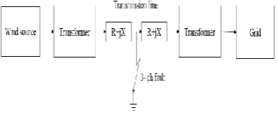
Fig. 2 Functional Block Diagram of Transient Stability Enhancement of of Squirrel Cage Induction
Generator
The electrical energy is generated from the wind source and it is stepped up or stepped down the voltage by means of transformer and it is transmitted to the grid by the transmission line. If the 3-phase to ground fault occurs in the transmission line, voltage instability may occur in the transmission line. For transient stability improvement, the unique property of the induction machines which is the possibility of reversing the direction of the rotating flux is employed.
In this method, after clearing the fault, operating mode of the induction machine is changed from the generating to the plugging mode for a short time. This leads to opposition between the rotating flux and mechanical torques, thus preventing the generator from further acceleration.
V. SIMULATION CIRCUIT
Fig. 3 Overall Simulink Diagram
By using MATLAB simulation software ,simu-link diagram is designed in-order to verify the outputs for enhancing the transient stability of grid connected squirrel cage induction generators.
Fig. 3.1 Simulation Diagram of Wind Turbine Control System
In this wind mill the induction machine is used. The plugging of the machine is done by interchanging any two stator terminals. The wind turbine is connected to the asynchronous machine. The output of the machine is connected to the universal bridge and it is connected to the transformer.
to get reversed immediately in the anticlockwise direction. Due to this the direction of the torque developed in the rotor becomes opposite to the direction of the rotating of the shaft. The braking torque causes a rapid reduction in speed. The rate of reduction of speed depends on the magnitude of the negative sequence voltage, applied to the motor, which is normally much lower than the rated voltage. When the speed drops to zero, the machine should be disconnected from the supply, fail in which the machine will begin motoring in the opposite direction.
VI.SIMULATION RESULT
Fig. 4 Output Waveform of Squirrel Cage Induction Generator
The output waveform shows the rotor current, stator current, speed variation of squirrel cage induction generator and the electromagnetic torque during normal operation, fault condition and the plugging mode operation. The disturbance occurred during the 3 phase to ground fault is shown from the period 0.10 to 0.17 sec. The period of 0.2 sec to 0.27 sec shows the motoring operation and after the time period of 0.3 sec, the normal generating operation is maintained.
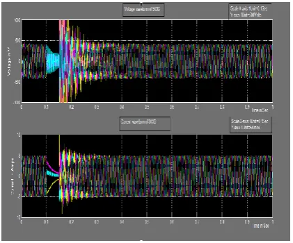
Fig. 4.1 Voltage and Current Waveform of Squirrel Cage Induction Generator
In the voltage waveform, the voltage is 415 V till 0.1 sec. then it denotes the fluctuations that occurs when connected to grid till 1.15 sec. The voltage
waveform from 0.15 sec to 0.25 sec denotes the transient that occurs during the 3-phase to ground fault. The voltage waveform from 0.25 to 0.35 denotes the plugging mode of operation in the machine thereby the fault is cleared and the stability is maintained after 0.37 sec. After clearing of fault the machine again acts as a generator and the voltage is maintained to 415 V as earlier Similarly in current waveform during the normal operation of generator, the current ranges to 5 A till 0.1 sec. Then the current waveform till 0.15 sec shows the disturbance when connected to grid. The current waveform of period 0.15 sec to 0.25 sec shows the plugging mode of operation. After 0.35 sec it attains stability and the normal mode of operation is maintained as earlier. From the simulation results, it can be inferred that the voltage fluctuations are reduced down and also the stability of the system is maintained.
VII.FUTURE SCOPE
By proper implementation with AVR(Automatic Voltage Regulator),various parameters of the power system can be monitored and controlled for enhancing efficiency and stability of the system.
VIII.CONCLUSION
Squirrel-cage IG is one of the popular types used in wind energy systems. This is due to its simplicity, reliability, low weight, low cost, and low maintenance cost. One of the main disadvantages of the wind farms that are equipped with this type of generators is the transient stability problem. In this work, a simple method was presented for preventing instability of grid connected squirrel-cage IGs, when a fault occurs in the network.
In this method, the speed of the generator is controlled by changing the operating mode from generating to plugging, for limited time interval after fault clearance. Simulation results confirm the effectiveness of the proposed method, which seems to be a more economical alternative in comparison with the other methods.
REFERENCES
[1] Abdel-AziaFouad (1982) ‘Proposed terms and definitions
for power system stability’ IEEE Trans. on Power Appart. and Syst.,, Vol. PAS-101, pp.1894-1897.
[2] Graham Rogers (1995) ‘Power System Oscillations’
IEEE Special Publication 95-TP-101.
[3] Hatziargyriou N., Karapidakis E., and Hatzifotis D.,
(1998 ) ‘Frequency stability of power system in large islands with high wind power penetration’ Bulk Power Syst. Dynamics Control Symp.—IV Restructuring, vol. PAS-102.
4] Kundur P.(1994) ‘Power System Stability and Control’
[5] Kundur, P Paserba,J. (2004) ‘Definition and Classification of Power System Stability’ IEEE Trans. on Power Syst., Vol. 19, No. 2, pp. 1387-1400.
[6] Murugesh Kumar K.(2008) ‘Induction and Synchronous
Machine.VIKAS PUBLICATION HOUSE PVT LTD.
[7] International Journal of Electrical and Electronics
Engineering Research (IJEEER)
ISSN(P): 2250-155X; ISSN(E): 2278-943X