http://www.sciencepublishinggroup.com/j/ijmsa doi: 10.11648/j.ijmsa.20170603.17
ISSN: 2327-2635 (Print); ISSN: 2327-2643 (Online)
Application and Development of Wavefront Sensor
Technology
Suyang Zhao
*, Xuemin Cheng
Advanced Manufacturing, Graduate School at Shenzhen, Tsinghua University, Shenzhen, China
Email address:
[email protected] (Suyang Zhao), [email protected] (Xuemin Cheng) *Corresponding author
To cite this article:
Suyang Zhao, Xuemin Cheng. Application and Development of Wavefront Sensor Technology. International Journal of Materials Science and Applications. Vol. 6, No. 3, 2017, pp. 154-159. doi: 10.11648/j.ijmsa.20170603.17
Received: May 1, 2017; Accepted: May 15, 2017; Published: June 6, 2017
Abstract:
Wavefront sensing technology can directly test the phase distribution of wavefront distortion and has the advantages of simple operation, real-time and large dynamic range. It is widely used in adaptive optics, laser beam quality diagnosis, laser atmospheric communication, optical element and optics system detection, quantitative phase microscope, human eye aberration measurement and other fields. This paper mainly elaborates application and development of wavefront sensing technology in different fields. Combining with the research, wavefront sensing technology is utilized in the high-volume detection of aspherical mobile phone injection and the application advantages in aspheric injection molding lenses error, test efficiency and the number of quality evaluation parameters are illustrated.Keywords:
Wavefront Sensor, Wavefront Distortion Compensation, Adaptive Optics, Injection Molding Aspheric Surface1. Introduction
In 1900, the Hartmann of German used the hole of the aperture technology to complete the world's first wavefront sensor. In 1971, Shack researched lens array and developed successfully the higher precision of Shack-Hartmann wavefront sensor [1]. In recent years, the rapid development of laser technology, computer technology, solid-state imaging devices, high-speed A / D devices, image processing method and microelectronics technology have injected new vitality into the development and application of wavefront detection technology.
From the mathematical model, the way to get wavefront phase information of different classification mainly includes two categories. One is measuring the wave front second derivative; The other is obtaining by first derivative of the wavefront. Current wavefront sensor technology generally includes shear interference wavefront sensor, curvature wavefront sensor, Shack-Hartmann wavefront sensor, pyramid wavefront sensor and self-reference wavefront sensor [2-3].
The wavefront sensor with high sampling frequency, phase distribution and the intensity distribution measured
simultaneously has been widely applied in optical processing, semiconductor manufacturing, defense equipment, aerospace and other fields. The wavefront sensing technology is needed in various optical, metal, soft material surface shape and beam wavefront distortion.
In the specific aspherical surface detection of injected mobile phone lenses, the existing measuring instruments such as interferometer, profiler, image instrument are all time consuming and the results of measurement rely on a certain adjustment benchmark, only reflect a single aspect of the geometric dimensions and could not fully reflect the state error in the effective aperture of mobile phone lenses. In the wave transmission mode measurement, the characteristics of the wavefront multidimensional data of the aspherical lenses are analyzed by using the clustering, scatter plot description to find out typical variables of Zernike coefficients and then proceed to do correlation analysis between the errors measured by other machines and wavefront typical variables. Wavefront measurement compared with the existing measurement method is efficient and promising.
2. Application
distribution of the optical wavefront. It has been widely used in the fields of adaptive optics, laser field, optical element surface detection, quantitative phase microscopy, subaperture stitching telescope system, ophthalmology, atmospheric laser communication. This technology is moving towards high precision, large dynamic range [4-5], high sampling rate, real-time and light weight.
2.1. Adaptive Optics
The image blur, jitter and image degradation under the observation of astronomical telescope caused by atmospheric turbulence have seriously affected the quality of astronomical imaging system, which constrains the resolution of astronomical telescope. The fast and random perturbation characteristics of atmosphere hardly uses the method of real-time compensation for wavefront distortion. Adaptive optics (AO) is the main method to compensate wavefront distortion to reduce the wavefront aberration of astronomical telescope imaging under the pupil surface, so that the system is always in the best state observation and can give full ability to effectively improve the telescope in observing the stars clarity. Similarly, in the satellite system or on the surface of the Earth's detailed view of the camera system, camera equipped with adaptive optical system can also effectively overcome the errors caused by atmospheric disturbance, and realize the high resolution imaging of ground objects. At present, adaptive optics technology is not only used in astronomical observation, space monitoring and laser transmission system, but also in satellite-to-ground observations.
The adaptive optics system is usually composed of three parts as shown in figure 1: a wavefront sensor, a wavefront controller and a wavefront corrector. The wavefront sensor is used to detect the wavefront distortion in real time. The wavefront controller converts the detected wavefront distortion signal into a control signal to control the wavefront corrector in real-time [6]. The wavefront corrector mainly used deformed mirrors, thin film mirrors and liquid crystal spatial light modulators to correct the wavefront error. The beam quality of the laser transmission system can be powerful guaranteed for compensation components of wavefront distortion. The research of adaptive optics in china is relatively late, and now some research institutes have established the technical basis of adaptive optics independently, and have made remarkable achievements.
Figure 1.The principle of adaptive optical system.
A typical wavefront sensor used in adaptive optics system, Shack-Hartmann wavefront sensor is widely employed because of high energy efficiency, large dynamic range and simple structure.
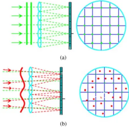
The basic structure of the Shack-Hartmann wavefront sensor is composed of a microlens array and a CCD camera as shown in figure 2. According to the relationship of simple geometrical optics, the average slope of the wavefront can be calculated by measuring the difference between the centroid coordinate position of the actual imaging spot and the centroid coordinate position of the reference imaging spot [7]. The actual wavefront can be reconstructed between the slope data and the Zernike coefficients [8].
Figure 2. The principle of Shack–Hartmann wavefront sensor: (a) the measuring system without wavefront aberration, (b) the measuring system with wavefront aberrations.
2.2. Laser Field
With the development of laser technology, the traditional method of measuring the beam quality of lasers by measuring the intensity distribution has been far from satisfying its requirements. Especially in large lasers like laser fusion, long-distance energy transport and multi-channel laser, the total optical path of each laser is very long, with a lot of optical parts surface, optical surface error and material nonuniformity. Accumulation will produce considerable wavefront error, which seriously affect the laser near field beam quality and far field focusing characteristics. So it is necessary to determine the phase distribution of the beam and the laser beam quality of real-time monitoring and precise control.
real-time correction of the laser beam emitted by system itself aberration, clean the beam, increase the laser output power, and improve the output laser near field intensity and phase distributed. In a system introducing wavefront distortion correction can easily detect the wavefront distribution and amplitude distribution of the laser beam, calculate the M2 factor of the laser beam and evaluate the various quantities of the far field spot such as PSF, diffraction limit and ambient energy far field characteristics [9]. The wavefront sensor can give the proportion of the aberration in the measured optical system while detecting the wavefront phase, and the quality of the laser can be improved according to the measured distortion phase combined with the corresponding wavefront correction device. Optical vortex detection is also an important application for wavefront sensor.
2.3. Optical Element Surface Detection
Large aperture aspheric components are mainly applied in military, aerospace fields, space remote sensing cameras,
astronomical telescopes. Large aperture aspheric
manufacturing is generally single or small batch production in need of high processing accuracy. In the fine grinding and rough polishing stage, the accuracy of the profiler and the aspheric surface error are in the same level of magnitude. Profiler can not meet the requirements and the large surface error of the aspheric surface and the low roughness exceed the dynamic range of the interferometer [10]. The Shack-Hartmann wavefront sensor has the advantages of large dynamic range and high measurement accuracy, low environmental requirements, short detection time and easy operation which used for the aspheric surface detection.
In civilian areas, free style glasses have been popularized, personalized and diversified. Due to the special surface of free surface, the use of profiler and ordinary interferometer detection are difficult to meet the needs of high-volume testing. Wavefront technology of large dynamic range and low cost can effectively measure and assess the free glasses lens [11].
In the manufacture of large scale of integrated circuit, lithography machine is the core equipment. Lithography projection lens aberration is an important factor affecting the imaging quality of lithography, resolution and critical dimension uniformity, which is one of the most important
indexes of lithography. Aberration detection of
Shack-Hartmann wavefront sensor is often used one of the methods of wave aberration detection.
2.4. Quantitative Phase Microscopy
In the quantitative phase microscopy for the detection of cell structure, the previous method is mainly hard to use the interference to obtain the phase information because of complex system, the measurement accuracy which is susceptible to vibration and other factors. The data reconstruction obtained by the system is very complex and need to make phase package and other steps. The application
of the wavefront sensor on a quantitative phase microscope greatly simplifies the system construction data processing process [12].
The measured phase delay caused by the sample can obtain the visualization of the biological structure. In biological cells, the different refractive index distribution will cause the different phase delay of the optical wave, which will transform the spatial difference of the refractive index into the contrast of the image. From the hartmann diagram, the phase information is extracted from each angle. Next, the three-dimensional distribution of refractive index is obtained from the phase map. The method is very promising in practical application.
2.5. Subaperture Stitching Telescope System
Astronomical observations require larger and better quality telescopes. For the space telescope, changes in the state of gravity and uneven temperature of each part of the main mirror will not make a better mirror and accurate alignment of the telescope in the ideal state. To reduce gravity deformation and thermal deformation, the traditional telescope usually uses a large stiffness of the main mirror, mirror material close to zero expansion coefficient and complex mirror support system. The large rigidity of the mirror is often very heavy, making the quality of the entire optical system increased, at the same time the technical difficulty is high, and greatly increase the cost. But the final quality is still not ideal.
A large aperture telescope composed of multiple mirror surfaces is faced with a series of technical challenges, of which the most difficult one is to solve the problem of phase error correction between the sub mirrors. In order to make the segmented telescope close to diffraction limited imaging quality, like the imaging quality of a single mirror telescope, each mirror must have high coplanar accuracy and need establish an active optical system because relying on the traditional mechanical alignment alone cannot reach the accuracy. The active optical system mainly includes the wavefront sensing system, the position and attitude calculation system and the position and attitude adjustment system. The mirror shape of the telescope can be detected in real time by wavefront sensor technology and hierarchical detection and gradual convergence strategy are adopted in the wavefront sensing system of high precision wavefront detection [13].
2.6. Ophthalmology
resolution, to obtain cell-level images in high quality.
The aberration of the human eye is the main factor that restricts the visual quality of the human eye. A prerequisite for correcting the human eye aberration in improving the visual ability is to measure the wavefront aberration of the human eye in real time, quickly and objectively. From the perspective of visual optics, wavefront aberration is more detailed than refractive error. To calculate the amount of corneal incision required by visual correction by wavefront aberration, doctor can guide the excimer laser to correct the cornea which can make patients get better visual acuity, and improve the visual quality of eyes. Therefore, the accurate wavefront measurement of the objective aberrations of the human eye has important clinical and experimental value in improving the visual quality of the human eye and the human eye refractive surgery [14].
2.7. Atmospheric Laser Communication
With the development of wireless technology and the increasing number of wireless multimedia applications, the demand for communication capacity and transmission rate is increasing, and the wireless spectrum is a kind of non-renewable resources, which makes the development of wireless communication face great difficulties and challenges. As a wireless communication system with no spectrum limitation and high transmission rate, the atmospheric laser communication system has the advantages of large capacity, wider bandwidth, high security, low cost and unrestricted spectrum resource restriction, which make it one of the most promising communication technology [15].
In the atmospheric laser communication, when the laser communication transmit through the earth atmosphere, the laser signal transmission is inevitably affected by atmospheric turbulence, resulting in light intensity flicker, beam drift, angle and phase fluctuation. Therefore the received optical signal is seriously disturbed, leading to the improvement of the error rate of the communication system,
decreasing channel capacity, seriously affecting the stability and reliability of laser communication.
Holographic mode wavefront sensor is a new type of wavefront sensing technique proposed in recent years, which realize the storage and detection of multi order aberration modes using the multiplexed holographic element. The output signal have an approximate linear relationship with aberration coefficient of each order in a certain range. In the process of converting measured wavefront sensor data into control signal of wavefront corrector, the complex matrix operation is not needed. The sensor is not sensitive to the non-uniformity of the intensity of the measured light wave, and can be applied to the strong turbulence and strong scintillation environment.
2.8. Aspherical Surface Detection of Mobile Phone Injection Molding
The application of small and medium diameter aspheric surface is mainly applied for civilian area, in the pursuit of high efficiency, low cost and high production. The main processing methods include mold forming technology, single point diamond turning technology, ultra precision grinding technology, CNC grinding technology and rapid polishing technology. More attention is paid to the control of low order aberrations.
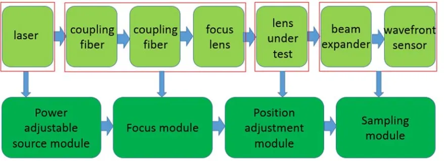
According to 2016 data, the global smart phone shipments is up to 1,470 million, which vastly demands injection molding aspheric lens module. The detection of injected aspheric lenses has three coordinate measuring instrument, interferometer and image instrument [16], but these measurements are geometry size, relying on the regulation of reference, which can not reflect the state error in the effective aperture of mobile phone lens and the measurement time is up to 5-40 minutes. Wavefront sensor in transmission model has great advantages. The basic structure of the Shack-Hartmann wavefront sensor in measuring transmission aspherical surface is illustrated in figure 3.
Figure 3. The optical path structure and module description of transmission measurement of injected aspheric surface.
The measured typical Zernike coefficients reflects aspheric injection molding error in the effective aperture and testing time is extremely short in less than two seconds. The typical wavefront Zernike coefficients can correspond with aspheric
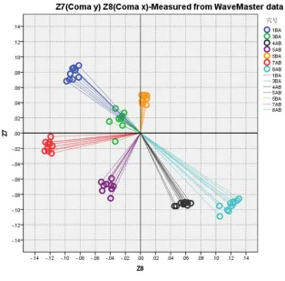
Figure 4. The relation between coma of Zernike coefficients and aspheric decenter: Left picture:coma measured from wavefront sensor, Right picture:aspheric decenter measured from profiler.
The wavefront test data can comprehensively and accurately reflect the aspheric injection molding error, improve the test efficiency of more than 90%, and reduce the
3. Conclusion
Wavefront sensor compared with the digital interferometer and profiler has a simple structure, no moving parts, antivibration, continuous and pulse light measurement, no coherence requirement and synchronously recording the change of wavefront widely used in real-time wavefront detection. Wavefront sensing technology, controllable binary optics and certain algorithms can theoretically match any sub-aperture with centroid coordinates in CCD surface, which will greatly improve the current dynamic range of sensor. Large diameter optical components can be measured by wavefront sensor coupled with step scanning and wave splicing technology in the transmission and reflection measurement.
Acknowledgements
This research was supported by a grant from the National Natural Science Foundation of China (Nos. 61275003, 61527826, 51327005) and the Shenzhen Science and
Technology Innovation Program (Nos.
JCYJ20160428182026575, JCYJ20151117173236192).
References
[1] L. Seifert, H. J. Tiziani and W. Osten. “Wavefront reconstruction with the adaptive Shack–Hartmann sensor,” Optics Communications. vol. 245. Stuttgart, Germany, 2005, pp. 255–269.
[2] D. Malacara and F. Roddier. Optical Shop Testing. Applied Optics, 2007, pp. 454-464.
[3] E. Abraham, T. Ogawa and M. Brossard. Interferometric Terahertz Wavefront Analysis. IEEE Journal of Selected Topics in Quantum Electronics, 2016, pp.1-1.
[4] E. Acosta and J. Sasian. Micro-Alvarez lenses for a variable dynamic range Shack-Hartmann wavefront sensor Microoptics Conference. IEEE, 2013, pp. 1-2.
[5] C M. Chia, K Y. Huang and E. Chang. “Hough transform used on the spot-centroiding algorithm for the Shack–Hartmann wavefront sensor,” Optical Engineering, 2016.
[6] L Kong, L Zhu and L Zhang. Real-time Controller based on FPGA and DSP for Solar Ground Layer Adaptive Optics Prototype System at 1-m NVST [J]. IEEE Photonics Journal, 2017, pp.1-1.
[7] G. Cao and X.Yu. “Accuracy analysis of a Hartmann-Shack wavefront sensor operated with a faint object,” Optical Engineering, 1994.
[8] C. Mcalinden, M. Mccartney and J. Moore. Mathematics of Zernike polynomials: a review. Clinical & Experimental Ophthalmology, 2011, pp.820-827.
[9] J V. Sheldakova, A V. Kudryashov and T Y. Cherezova. “Beam quality measurements with Shack-Hartmann wavefront sensor and M2-sensor: comparison of two methods,” Proceedings of SPIE - The International Society for Optical Engineering, 2007.
[10] P Su, M Khreishi and Su T. Aspheric and freeform surfaces metrology with software configurable optical test system: A computerized reverse Hartmann test. Optical Engineering, 2013.
[11] J. Yu, F. Fang and Z. Qiu. “Aberrations measurement of freeform spectacle lenses based on Hartmann wavefront technology,” Applied Optics, 2015, pp.86-94.
[12] Huang Chenxi. research on key technologies of Shack Hartmann wavefront sensor. Zhejiang University, 2013
[13] S Chen and G Wang. Subaperture test of wavefront error of large telescopes: error sources and stitching performance simulations. Proceedings of SPIE - The International Society for Optical Engineering, 2014.
[14] K Dillon. Fast and robust estimation of ophthalmic wavefront aberrations. Journal of Biomedical Optics, 2016.
[15] S Kim, C Park and T H Kim. Free space optical communication system based on wavefront sensorless adaptive optics [J]. Proceedings of SPIE - The International Society for Optical Engineering, 2009.
[16] Y. Furukawa, Y. Takaie and Y. Maeda. “Development of one-shot aspheric measurement system with a Shack-Hartmann sensor,” Applied Optics. vol. 55, 2016.