A Study on the Control Methods Based on
3-DOF Helicopter Model
Junshan Gao
School of Automation/Harbin University of Science and Technology, Harbin, China Email: [email protected]
Xinghu Xu, Chen He
School of Automation/Harbin University of Science and Technology, Harbin, China Email: [email protected]
Abstract—The 3 degree of freedom (3-DOF) helicopter system is a typical higher-order times, instability, multi-variable, nonlinear and strong coupling control system. This paper presents the analysis of the mathematical model and the basic principle of PID control and fuzzy PID control, which are based on 3-DOF helicopter systems. In allusion to balance control of 3-DOF helicopter system, PID controller and fuzzy PID controller are designed respectively to control the model. The MATLAB simulation results demonstrate the control effects of both controllers achieve the requirements in this system, and fuzzy self-tuning PID shows more advantages.
Index Terms—helicopter system, Fuzzy PID, matlab, pitching axis, lateral axis, revolving shafts
I. INTRODUCTION
The 3 degree of freedom (3-DOF) helicopter model is a typical multi-input and multi-output system with high-order, which contains the properties of strong channel coupling and high nonlinearity. Since the motion equations of its three axes in elevation, pitch, and travel are always used to simulate the dynamic characteristics of real helicopter, 3-DOF helicopter model becomes an efficient tool for teaching and researching in control method [1], [2].
Many efforts have been demonstrated it is difficult to illustrate the dynamic characteristic of the helicopter, because of its extremely complex and particular flying state. Normally, its dynamic characteristics will be correspondingly varied with flying altitude and flying state, all of which are nonlinear and multivariable coupling. Consequently, it is probably impossible to achieve formulations of the helicopter as well as its accurate models. It seems that the helicopter models used in engineering tend to be processed simply. In this dissertation, a 3-DOF helicopter model as the object of study, so as to researching the attitude control and simplifying the complexity of research [3].
According to the dynamic trait of pitch axis, elevation axis and travel axis, the system mathematic model was established, the model offered basic for the PID control and theoretical support for the controller improvement. Finally, the fuzzy control was used to control the system. The control results of the simulation experiments proved that the using of the fuzzy control worked better than the pure PID controller. Compared with the traditional PID control, it had a remarkable improvement. Both the PID controller and the fuzzy controller had their respective advantages. Based on their excellent merits, PID and fuzzy controller were combined together as one controller which fit together with switch and weighted value. It optimizes the flying gesture of the helicopter [4], [5].
II.SYSTEM MODELING
A 3-DOF helicopter control system introduced in this paper, is inherently unstable with MIMO, nonlinear and high degree of coupling. This system consists of some basic components, such as a pedestal, an equalizer bar, counterbalance and blades. Based on pedestal for fulcrum, the equalizer bar can be driven to pitch and turn. Counterbalance and blades are separately installed on both ends of the equalizer bar. Accordingly, the equalizer bar due to the lift force which the blades produced to pitch (based on pedestal for fulcrum). Under the similar condition, equalizer bar turns by velocity different of two blades pitching (based on pedestal for axis). In order to measure data of revolving shafts and pitch axis of equalizer bar and lateral axis of propellers, encoders are installed respectively on revolving shafts and pitching axis of equalizer bar and lateral axis of propellers. Two blades are driven by two Direct Current Brushless Motors, blades are proposed power simultaneously. Hence, models are established for three axes (degree of freedom) as the characteristics of the system [6].
A. Pitching Axis
Structure of pitching axis as Fig.1,
Manuscript received May15, 2011; revised September28, 2011; accepted January8, 2012 .
Figure 1 Structure of pitching axis
Torque of pitching axis is generated by two propeller-motors producing the direct lift F1 and F2. Helicopter increases when lift Fh is greater than gravity G; conversely it drops. Assuming that helicopter is hung in the air and the degree of pitch is zero; equations can be given as follows:
1 1 1 1 2 1 1 1 2 1
( )
( )
e h
e g c s g
J l F l G l F F l G
J Kcl V V T K l V T
ε ε
= − = + −
= + − = −
&&
&&
(1)
In equation (1), Je is the rotational inertia of the
pitching axis; V1 and V2 are voltages of two motors;
c
Kis the lift constant for blades motor; l1is the distance from fulcrum to motors; l2is the distance from fulcrum
to counterbalance; Tg is the effective gravity torque
produced by gravity of pitching axis; mh and mb are
respectively quality of blades and counterbalance of helicopters;
ε
&&
is the rotation acceleration of pitching axis.If gravity disturbance torque is ignored, the transfer function of this part of the system as following equation:
( ) 1
2
K l
s c
V J s
s e
ε =
(2)
Lateral Axis
Structure of Lateral axis as Fig.2,
Figure 2 Structure of lateral axis
From above image, lateral axis controlled by lift produced by two blades. If the lift created by F1 is greater than that which is created by F2, blades will tilt, and then there will be a lateral force to make helicopter turn around the base, i.e.
We can get equation as follows:
1 2 (1 2)
p p p c p c p d
J p Fl&&= −Fl =K l V V− =K l V
(3)
In equation (3),Jp is the rotational inertia of the
lateral axis, the distance from fulcrum to motor, and P the rotation acceleration of the lateral axis.
The transfer function of this part of the system can be given by formula (4) as follows:
2
( ) K l
p s c p
V J S
d p
= (4)
B. Revolving Shafts
Structure of revolving shafts as Fig.3,
Figure 3 Structure of revolving shafts
Its dynamics equation is as follows:
1 sin( )
t
J r&= −G p l
(5)
In equation (5), r is the rotating speed, rad/sec as one unit. Sin (p) is the sine value of lateral angle p. Generally the angle is small, approximately considered as
s i n (p) ≈ p here. The transfer function of this part of
the system can be got by formula (6) as follows:
( ) 1
( )
Gl r s
P s J S t
= −
(6)
III.CONTROLLER DESIGN
Helicopter control requires the ability to produce moments and forces on the vehicle to produce equilibrium and to change the helicopter's velocity, position and orientation [7]. The problem of helicopter control has received much attention and especially during the last two decade [8]-[10]. The usage of the traditional PI, PD controllers is not satisfied because the helicopter parameters are very dependent on the operating point. These controllers only work well in a very small area around that set point. Also, when dealing with multivariable systems, one of the major concerns are the cross-couplings of he system [11].
A. PID Controller Design
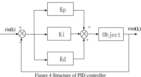
Figure 4 Structure of PID controller
PID controller is a linear controller, the control rules as follows [12]:
0
( ) ( ) p( ( ) i t ( ) d derror t )
u t k error t K error t dt K dt
= +
∫
+ (7)Where, error(t) is the deviation composed by given value rin(t) and actual output value yout(t), Kp, Ki, Kd, respectively known as proportional coefficient, integral coefficient and differential coefficient. The effect of the three links of PID control is obvious:
a) Proportional link: the deviation signal is reflected proportionally, and the controller would produce effect to reduce deviation if deviation produced;
b) Integrating link: mainly used to eliminate static errors, and improve indiscrimination degree of the system;
c) Differential modulus, to reflect the rates of deviation signal change, and to lead in an effective early modify signal in system before error signal becomes too large, to speed up the responsiveness of the system, and to reduce the setting time.
Then, three parameters operate convenient in practical control [13].
1) Controller of Pitching Axis
According to equation (7), a PD controller is designed as follows:
( )
s ep c ed
V =K ε ε− +k ε&
(8)
In equation (8),
ε
represents actual angle of pitch, andε
crepresents the pitch angle of expectation.The transfer function of this part of the system can be given as follows:
1 2
1 1
/
( )
( )
/
/
c ep e
c c ep e c ep e
k k l
J
s
s
s
k k l
J s
k k l
J
ε
ε
−
=
−
−
(9)In equation (9), the denominator can be expressed as
follows:
2 2
0 0
2
s + ξω ω+ (10)
Peak time as
2
0 (1 )
p
t
π
ω
ξ
=
− , by choosing expected
peak time
t
pand damping ratio, to determine thek
epand
k
ed to satisfy expectations response. 2) Controller of Lateral AxisThe rotation speed of the helicopter can be controlled by changing the size of slant angle of lateral axis. According to equation (7), we design a PD controller as follows,
( )
d pp c pd
V =K p−p +k p& (11)
The transfer function of this part of the system can be got as follows,
/ ( )
( ) 2 / /
c pp p e
c c pd p p c pp p p k k l J
p s
p s s k k l J s k k l J −
=
− − (12)
Then, as the controller of pitching axis, we can determine the
k
ppandk
pdby choosing expected peak time and damping ratio to satisfy expectations response.3) Controller of revolving shafts
According to equation (7), we design a controller to get expected Lateral Angle,
( ) ( )
c rp c ri c
P =K r−r +k
∫
r−r (13) The transfer function of this part of the system can be get as follows:1 1 1
1 1
/ ( )
( ) 2 / /
rp r t
c rp t ri t
k Gl s k Gl J r s
r s s k Gl J s k Gl J
− +
=
− − (14)
This controller can also be designed according to the second-order controller, by choosing expected peak time
p
t
and damping ratio, to determine thek
rp andk
rd to satisfy expectations response.B. FUZZY-PID Controller Design
Fuzzy rules
PID
controller Actuator
Controlled Object Perturbance
Kp Ki Kd
y e
r
_
de dt
Figure 5 Structure of fuzzy self-adaptive PID controller
In view of the different error e and error rate, different PID control parameters of Ki, Kd, Kp are demanded, and we set rules as follows.
1) When | e | is big, for the system to have good tracking performance, we should take large Kp and small Kd; meanwhile, in order to avoid large overshoot in system response, we should set a limit to the integral effect, usually we take Ki = 0.
2) When | e | and |ec| are median size, for the system to have a small overshoot, we should take small Kp. In this case, Kd is bigger impact on the system, we should take a small value, Ki should be proper.
3) When | e | is small, for the system to have a good stability, we should take big Ki and Kd; meanwhile, in order to avoid appearing oscillation within the set value, and considering anti-interference performance of the system ,when |ec| is large, Kd should be taken a smaller value, and vice versa[15].
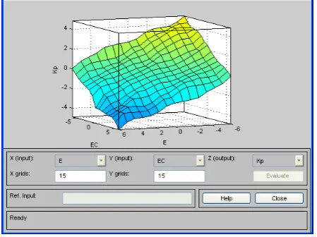
Three-dimensional diagram of rules of Kp,Ki,Kd as Fig. 6, Fig. 7 and Fig.8.
Figure 6 Three-dimensional diagram of rules of Kp
Figure 7 Three-dimensional diagram of rules of Ki
Figure 8 Three-dimensional diagram of rules of Kd
* * * { , } { , } { , }
i cj p i cj i
i cj d Kp Kp e e q
Ki Ki e e q
Kd Kd e e q
⎧ = + ⎪⎪ = + ⎨ ⎪ = + ⎪⎩ (15)
In equation (15), Kp, Ki and Kd are initial-value of three control parameters of self-adaptive fuzzy PID controller, Kp,Ki,Kd are the adjusted parameters of PID, qp,qi and qd are corrective factors of PID, {ei, eci} is error e and error rate ec corresponding to output values of the fuzzy control rules table. In process of establishing the fuzzy rule base, we should consider that input and output variables of the fuzzy controller are accurate quantity, and fuzzy reasoning is the quantity of fuzzy signal [15].
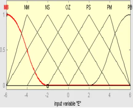
In order to adapt to more systems, membership functions of this paper selected smoothing continuous Z type membership function at negative boundary, and smoothing continuous S membership function at positive boundary, and we choose triangular type membership function which has higher delicacy in the middle part. The universe of error e, error rate ec and the output P is {- 6... 6}, and the universe of the output I and D is {- 0.6... 0.6}.Membership function diagram as Fig. 9, Fig. 10 and Fig.11.
Figure 9 Membership function diagram of E
Figure 10 Membership function diagram of Kp
Figure 11 Membership function diagram of Ki
And in this paper , rules of Fuzzy PID controller as TableⅠ
TABLE I
CONTROL RULES OfΔKp,ΔKi,ΔKd
Control rules of ΔKp:
ec
p
K Δ
e
NB NM NS ZO PS PM PB
NB NM NS ZO PS PM PB PB PB PM PM PS PS ZO PB PB PM PM PS ZO ZO PM PM PM PS ZO NS NM PM PS PS ZO NS NM NM PS PS ZO NS NS NM NM ZO ZO NS NM NM NM NB ZO NS NS NM NM NB NB
Control rules of ΔKiandΔKd:
NB NM NS ZO PS PM PB NB NB NM NM NM ZO ZO NB NB NM NM NS ZO ZO NM NM NS NS ZO PS PS NM NS NS ZO PS PS PM NS NS ZO PS PS PM PM ZO ZO PS PM PM PB PB ZO ZO PS PM PB PB PB NB NM NS ZO PS PM PB PS PS ZO ZO ZO PB PB NS NS NS NS ZO NS PM NB NB NM NS ZO PS PM NB NM NM NS ZO PS PM NB NM NS NS ZO PS PS NM NS NS NS ZO PS PS PS ZO ZO ZO ZO PB PB
Min, and Or method as Max according based on fuzzy control rules and fuzzy membership functions. Implication method is Min, Aggregation method is Max and considering defuzzification method as centroid. According to all linguistic values in rule tables, its forms can be used (i.e. If…then) in order to complete fuzzy reasoning section, and prepare simulation in next step in simulink, And relations are used between outputs and inputs to edit rules [16].
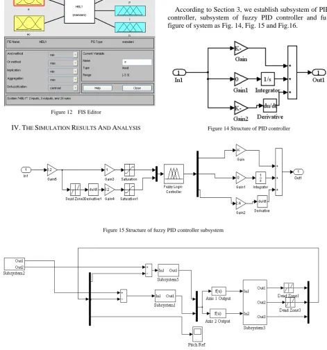
FIS Editor in matlab of Fuzzy PID controller as Fig.12.
Figure 12 FIS Editor
IV.THE SIMULATION RESULTS AND ANALYSIS
According to transfer function of controlled object and relationship of every link which are got in section 2 , we build the controlled object model in matlab/simulink as Fig.13.
Figure 13 Structure of controlled object model
According to Section 3, we establish subsystem of PID controller, subsystem of fuzzy PID controller and full figure of system as Fig. 14, Fig. 15 and Fig.16.
Figure 14 Structure of PID controller
Figure 15 Structure of fuzzy PID controller subsystem
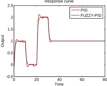
The set value of input module is: input 1 is set as setting value of the pitch, and input 2 is set as setting value of the revolving shafts. The expected control effect is: the helicopter raise at first falls at 10 seconds, rises again at 20 seconds, and falls back to the initial lift at 30 seconds. It starts to revolve from 40 seconds, counterclockwise rotation at first, and clockwise rotation at 50 seconds [17].
According to the intended target, in simulation process, we set input 1 initial as the unit step, and the set value reduced to 0 at 10 seconds, added to 2 at 20 seconds, and reduced to unit step at 30 seconds; we set input 2 initial as 0, and it reduced to -1 at 40 seconds, added to 0.5 at 50 seconds, then kept uniform. We add a pulse disturbance angle of pitch at the 42 seconds to simulate collision disturbance of the environment. Response curve of simulation figures without delay link shown in Fig.17 and Fig.18.
0 20 40 60 80
-0.5 0 0.5 1 1.5 2 2.5
Response curve
Time
O
ut
put
PID FUZZY-PID
Figure 17 Response curve of angle of pitch without delay
0 20 40 60 80
-1 -0.8 -0.6 -0.4 -0.2 0 0.2 0.4 0.6
Response curve
time
out
p
ut
PID FUZZY-PID
Figure 18 Response curve oflateral angle without delay
Through the simulation curve, we can get two groups of system performance data of control modes, shown in TableⅡ.
TABLE II
SYSTEM PERFORMANCE DATA OF CONTROL MODES
Setting time
Oversho ot
Static errors of pitching angle
Static errors of lateral angle
PID
Fuzzy-PI D
3.395
2.682
4.8 %
0
0
0
3%
0
Add a delay link about 0.02s into model, then, response curve of angle of pitch with delay and response curve of lateral angle with delay shown in Fig.19 and Fig.20.
0 20 40 60 80
-0.5 0 0.5 1 1.5 2 2.5
Response curve
Time
O
ut
put
PID FUZZY-PID
Figure 19 Response curve of angle of pitch with delay
0 20 40 60 80
-1 -0.8 -0.6 -0.4 -0.2 0 0.2 0.4 0.6
Response curve
time
out
put
PID FUZZY-PID
Figure 20 Response curve of lateral angle with delay
irregular shocks appeared. Correspondingly, system of fuzzy PID control method is not influenced almost.
Ⅴ.CONCLUSION
The paper focus on analyzing 3-dof helicopter model, and designing the PID controller and the PID parameters self-adjusting controller, which depend on fuzzy inference functions to achieve.
Simulation results demonstrate that both of the controllers can be applied into 3-dof helicopter system to keep stable. Admittedly, the accuracy improved and the speed met the requirements of 3-dof helicopter model. In addition, the fuzzy PID control method has better adaptability for parameters change and environmental change, so it is applicable to environment with a delay and other actual existence but working trouble. With comparison, fuzzy PID controller could probably develop the characteristics of stronger robustness, better dynamic response, more quickly regulating time and smaller overshoot of fuzzy control. As a result, fuzzy PID controller performances better than PID controller dose.
REFERENCES
[1] Ge Jinlai, Zhang Chenghui, and Cui Naxin. Fuzzy
Self-tuning PID Controller in the 3-DOF Helicopter Experimental System. Information and Control. Vol.39,pp. 342-347.June, 2010
[2] Liang Li-min, Yin Ping-lin. Optimal Design of the TRMS Based on MATLAB. Microcomputer Development. Vol.14, No.4. pp.25-30. Apr,2004.
[3] Xiaoxiao Zhao. The 3 Dof Helicopter Control System
Based on PID Contmller. Joumal of Shandong Electric Power College. Vol.12 No.4, pp. 52-55.
[4] Mostafa A. Hamood, Rini Akmeliawati, Ari Legowo.
ultiple-surface sliding mode control for 3DOF helicopter. 2011 4th International Conference on Mechatronics (ICOM). Page(s): 1-5, 2011 .
[5] Takamuku, K.; Ishitobi, M.; Kumada, T.; Nishi, M.;
Kunimatsu, S.; Redesign implementation of a nonlinear sampled-data controller for a 3-DOF model helicopter. SICE Annual Conference (SICE), 2011 Proceedings of Publication Year: 2011 , Page(s): 1014 – 1018.
[6] Wang Xiu-yan, Zhao Chang-li, and Li Zong-shuai. Study
on Simulation of 3-DOF Helicopter Model Control Based on System Decomposition. Vol.27 No.6. December 2009.
[7] R. W. Prouty, Helicopter Performance, Stability, and
Control, Krieger Publishing Co., Inc., 1995.
[8] A. Isidori and C. I. Byrnes, "Output regulation of nonlinear systems," IEEE Transactions on Automatic Control, vol. 35, pp. 131-140, 1990.
[9] J. K. Vi, Y. Ma, and S. S. Sastry, "Nonlinear Control Of A Helicopter Based Unmanned Aerial Vehicle Model,"
[10] T. J. Koo and S. Sastry, "Output tracking control design of a helicopter model based on approximate linearization," in Proc. 37'" IEEE Conference on Decision and Control, Tampa, FL, 1998, pp. 3635-3640.
[11] Velagic, J., Osmic, N.; Identification and control of 2DOF nonlinear helicopter model using intelligent methods. Systems Man and Cybernetics (SMC), 2010 IEEE International Conference on. Page(s): 2267 – 2275, 2010 .
[12] Jinkun Liu. Advanced PID control Base on MATLAB
simulation. 2nd edition. Beijing: Publishing House of Electronics Industry, 2004.
[13] Qiu Li, Zeng Gui-e, and Zhu Xue-feng. A Comparative
Study of PID Turning Methods. Industry Control and Application. Vol. 24, No.11. pp.27-31.
[14] Zhou Liyin, Zhao Guoshu. Application of fuzzy-PID
control algorithm in uniform velocity temperature control system of resistance furnace. V01.29 No.2. pp. 405-409. Feb.2008.
[15] Shiyong Li. Fuzzy control.neural control and intelligent control theory. Heilongjiang: Harbin Institute of Technology Press,1998
[16] Yang Li. Computer control and simulation technology. 2nd edition. Beijing: ChinaWaterPower Press, 2006.
[17] Yue Xin-cheng, Yang Ying, and Geng Zhi-yong. No
Steady-state Error Tracking Control of 3-DOF Experimental Helicopter System. Journal of System Simulation. Vol.19, NO.18. pp.4279-4283. Sep. 2007.
Junshan Gao born in 1962, he is professor of Harbin University of Science and Technology in Harbin, China. Master Tutor, Doctor of Engineering. He graduated from Harbin University of Science and Technology in Harbin, China. His research fields are intelligent control, chaos theory, Power Electronic Technology.
He completed four research tasks , such as Heilongjiang natural science fund item, Harbin Reserve leader fund item and so on. He is author of more than 20 papers published in international peer reviewed journals.
Prof. Gao is Councilor of Harbin Control Academy.
Xinghu Xu born in 1986, Bachelor of Engineering is a graduate of North China University of Technology in Beijing, China. His research fields are intelligent control and advanced detection technology. He completed some parts of research tasks guidance
of tutor.