Designing of Advanced Crowbar Protection
System for DFIG Coupled Wind Energy
Conversion System at Different Fault Conditions
Divya Chauhan Sandeep Kumar Goel
PG Student Professor
Department of Electrical Engineering Department of Electrical Engineering College of Technology, G.B.P.U.A.T (Pantnagar) College of Technology, G.B.P.U.A.T (Pantnagar)
Abstract
In suggested protection technique, an advanced Active Crowbar Protection system is proposed for Doubly-Fed Induction Generator (DFIG) coupled Wind Energy Conversion System (WECS). An active Crowbar Protection system with relay components is designed for DFIG based Wind Turbine for analysis of Low Voltage Ride through (LVRT) at different fault conditions. DFIG controlled model is connected to utility based substation in standalone mode and assumed to be connected to large grid by taking substation as programmable voltage source. A large number of lumped load can be connected to the line. DFIG performance analysis with and without Crowbar protection is done for all kinds of faults and effectiveness of proposed fault protection technique have been demonstrated by the results. This work has motivated by the controlling of DFIG and behavior analysis at the time of fault.
Keywords: DFIG, WECS, Low Voltage Ride through (LVRT), Crowbar, Fault Ride through (FRT)
________________________________________________________________________________________________________
I. INTRODUCTION
The DFIG is one of the most commonly deployed large grid-attached wind turbine systems. Indeed, when correlate with the full-scale power converter WT concept, the DFIG proposal some benefit ,such as lesser inverter and output filter costs due to low rotor-and grid-side power conversion ratings(25–30%) [1]. However, DFIG-based WT are very sensitive to the grid disturbances, especially to other voltage dips. The Feedback control of DFIG system is a part of research in extreme level and a lot of things are to improve the performance as application of feedback system for more energy efficiency and low voltage ride through in case of fault appeared inside the generator system. The performance of DFIG system with feedback controllers is required to improve the present application of controllers.
II. PROBLEM AREAS
The increment in the amount of power from decentralized, renewable energy systems especially wind energy systems, requires strong grid code requirements for maintaining a safe and stable operation of the network. Operation during grid voltage faults requires the condition that wind turbines must remain connected to the grid and support the grid by generating the reactive power in order to restore quickly the grid voltage after the fault condition.
Fig. 1: Schematic diagram of DFIG wind turbine system
III. TYPES OF CROWBAR PROTECTION CIRCUITS
The circuit of crowbar protection is commonly uses to protect converter circuit during dips in voltages. The main cause of this solution is to limit high current in rotor circuit and limit high voltages in DC link. It is possible to ride through the fault condition in line of power system by using crowbar protection scheme.
DC Side Crowbar Protection:
DC side crowbar made up of a chopper and a resistor that are added across to the DC bus of the converter. It can limit the DC voltage from exceeding safe range. The chopper module is not necessary for fault ride-through operation but it enhances the normal range of DFIG operation by smoothing the dc-link voltage during more misbalance of active power on the rotor side and grid side converters. The rotor side converter has to be dimensioned to handle the high current transient in addition to the normal load. Thus oversized constituents have to be used and make this scheme unattractive.
Rotor Side Crowbar Circuit:
The crowbar circuit is usually implemented between the rotor circuit and rotor-side converter to provide a bypass for the high transient rotor current, which is induced by voltage dip. Initially, the industrial solution implemented was just to short circuit the rotor windings with the crowbar circuit. This conventional crowbar circuit can be constructed in many ways. The rotor can be short-circuit by two pairs of anti-parallel thyristor joined between the phases. Another substitute is to use a half-controlled thyristor bridge. The third feasibility is to retrieve the phase current with Diode Bridge and to work with a single thyristor to trigger the crowbar.
IV. DFIG WITH CROWBAR PROTECTION
To protect the rotor side converter from tripping due to over-currents in rotor circuit and overvoltage in DC link during grid voltage dips a crowbar is installed in conventional DFIG wind turbines. It is a resistive network connected to the rotor windings of the DFIG. The crowbar limits the voltages to provide a safe route for the currents by bypassing the rotor by a set of resistors. When the crowbar is activated the rotor side converters pulses are disabled and the machine behaves like a squirrel cage induction machine directly coupled to the grid. The magnetization of the machine that was provided by the RSC in nominal condition is lost and the machine absorbs a large amount of reactive power from the stator and thus from the network [6].
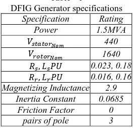
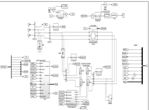
Below fig. 2, shows the typical arrangement of crowbar protection of DFIG fault response in MATLAB. The system resembles the IGBT and resistor with relay protection model. The difference lies in the protection block. Table 1, shows the DFIG generator specifications.
Table - 1
DFIG Generator specifications Specification Rating
Power 1.5MVA
𝑉𝑠𝑡𝑎𝑡𝑜𝑟𝑁𝑜𝑚 440
𝑉𝑟𝑜𝑡𝑜𝑟𝑁𝑜𝑚 1640
𝑅𝑠, 𝐿𝑠𝑃𝑈 0.023, 0.18
𝑅𝑟, 𝐿𝑟𝑃𝑈 0.016, 0.16 Magnetizing Inductance 2.9
Inertia Constant 0.0685 Friction Factor 0
Fig. 2: MATLAB Simulation Block for Crowbar Protection
V. MODELLING OF PROPOSED ACTIVE CROWBAR
A controllable DFIG system or power system is required a protection coordination inside of controlling system. Even load, line and plant have many protective equipment and operates effectively during fault, but protection from generator side cannot be avoided. Wind power plant is one of the most disturbing type generating system in case of worst weather condition or fault condition. In such case wind power plant require additional protecting equipment inside of generator system. Such protective equipment is designed for some basic condition during fault condition [7],[8]:
1) Generator machine should not be disconnected from the supply line. It means that machine should not be in turn off condition at the time of fault.
2) The speed of wind turbine required to be in operating condition in case of any types of fault.
3) The controlling circuit of DFIG has to be disconnected from stator side and required to remain in operating condition when fault appears.
4) Mechanical power of wind turbine can be controlled in case of fault conditions.
The active crowbar circuit has modeled into MATLAB and it is a combination of diode rectifier and one IGBT device. A resistor (greater than the value of rotor resistance) has taken in series with IGBT for drop in power at the time of fault. Active crowbar circuit is connected in parallel of the rotor side converter as given in schematic block diagram. The crowbar protection scheme applied in this work allows operation of low voltage ride through in case of fault appears inside of generator. Whole crowbar protection scheme can be divided into five different parts as follows:
1) Crow protection Control circuit.
2) Crowbar control on turbine speed regulator. 3) Rotor side converter switching control circuit. 4) Active crowbar triggering.
5) Feedback rotor supply to machine switching control.
VI. CROWBAR PROTECTION CONTROL CIRCUIT
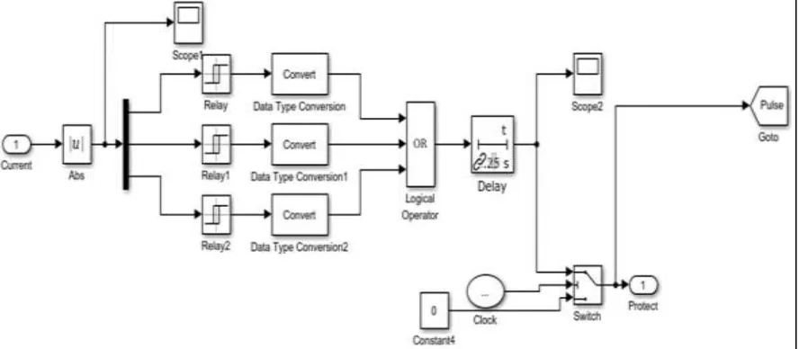
The protection control circuit is a combination of relays operating at fault condition. The current from rotor side converter has passed through this protection control circuit, and this circuit have ability to bypass a tripping signal in case of fault appears inside the converter model.
The output signal from crowbar protection control model has connected to all other control circuit for the tripping and activation at the time of fault appeared: rotor speed regulator model and rotor side converter model will be disabled on tripping sample passed from crowbar protection control circuit. Schematic view of crowbar protection control is presented below in image view and all blocks and switches are coordinated with all control circuits.
Fig. 4: Simulation Block for inner circuit of crowbar protection scheme
VII.SIMULATION RESULTS AND DISCUSSION
The effects on the rotor current are shown in Figure below. The protection response may be viewed during the fault period from 1 to 1.5 seconds. This applies to all fault modeling simulations in this report. The rotor current decreases when the additional crowbar circuit is connected while the rotor voltage is increased. DC link voltage is also decreased.
Results for 3-Phase Fault Condition with Crowbar:
Iabc Rotor with Crowbar Protection
Vdc Link Voltage without Crowbar Protection
Vdc Link Voltage with Crowbar Protection
Results for 1-Phase Fault (LG) condition with Crowbar:
Iabc Rotor with Crowbar Protection
Vdc Link Voltage without Crowbar Protection
Vdc Link Voltage with Crowbar Protection
Here the fault was applied between 1 and 1.5 seconds by setting the fault block to generates a short circuit between all 3 phases [3], [4]. The protection was switched on at 1.1 seconds by applying a signal to the crowbar resistor switch. We can observe that after connecting the protection, the DC link voltage is greatly reduced and rotor voltage is increased while rotor current is decreased.
Rotor current values with crowbar and without crowbar protection system are 0.2 P.U. and 2.8 P.U. respectively for 3 -phase faults and 0.7 P.U. and 1.8 P.U. for single phase fault. Similarly Vdc Converter link voltage values with crowbar and without crowbar protection system are 1550 V and 2500 V respectively for 3-phase faults and 1175V and 1225 V for single phase fault. The crowbar protection is employed to attenuate severe faults. The excess energy of the rotor (from high currents due to fault) is to be dissipated in the resistors.
VIII. CONCLUSION
These all conditions and observations were obtained without disconnecting the turbine from system as turbine speed was not slowdown to rest or shutdown at the time of fault. Results of turbine speed are verified to this objective. Electromagnetic torque is at minimum value of about 0.02 PU and it shows that DFIG machine is not shut down at the time of fault. The value of crowbar resistance should be taken in such a way so that the effect of resistance does not cause any adverse effect in the system operation. Suggested Crowbar protection system is simple, accurate and free from false triggering operation and might be implemented in the systems where relative cost of the system is a consideration. Advanced Crowbar Protection with relay controlling technique of feedback system will enhance efficiency with fault ride through (FRT) and low voltage ride through (LVRT) operation. The rotor current, rotor speed, DC-link voltage, active power and reactive power are affected by a certain value of the crowbar resistance therefore, the crowbar resistance value should be chosen carefully and according to the rating of system.
REFERENCES
[1] Jackson John Justo, Francis Mwasilu, Jin-Woo Jung , “Doubly-fed induction generator based wind turbines: A comprehensive review of fault ride-through strategies”, IEEE journal for Renewable and Sustainable Energy Reviews 45 (2015) 447–467, http://dx.doi.org/10.1016/j.rser.2015.01.064
[2] Kenneth E. Okedu “Stability Enhancement of DFIG-based Variable Speed Wind Turbine with a Crowbar by FACTS Device as Per Grid Requirement”, INTERNATIONAL JOURNAL of RENEWABLE ENERGY RESEARCH, Vol.2, No.3, 2012.
[3] Bhinal Mehta , Praghnesh Bhatt , “Small signal stability analysis of power systems with DFIG based wind power penetration”, IEEE journal for Electrical Power and Systems58(2014)64–74, http://dx.doi.org/10.1016/j.ijepes.2014.01.005
[4] Christian Wessels, Fabian Gebhardt and Friedrich W. Fuchs, "Dynamic Voltage Restorer to allow LVRT for a DFIG Wind Turbine", International Symposium on Industrial Electronics (ISIE), 2010, doi:10.1109/ISIE.2010.5637336.
[5] J. Lopez, P. Sanchis, X. Roboam, L. Marroyo “Dynamic behaviour of doubly fed induction generator during three phase voltage dips” IEEE Transactions on Energy Conversion, vol. 22, no. 3, 2007, pp. 709-717.
[6] R. Takahashi, J. Tamura, M. Futami, M. Kimura and K. Idle, “A new control method for wind energy conversion system using double fed synchronous generators”, IEEJ Trans. Power and Energy, vol. 126, no. 2, pp. 225-235, 2006.
[7] O. Wasynczuk, D. T. Man, and J. P. Sullivan, “Dynamic behaviour of a class of wind turbine generator during random wind fluctuations”, IEEE Trans. on Power Apparatus and Systems, vol. PAS-100, no. 6, pp. 2837-2845, 1981.
[8] K. E. Okedu, S. M. Muyeen, R. Takahashi, and J. Tamura, “Participation of FACTS in stabilizing DFIG with crowbar during grid fault based on grid codes”, IEEE-GCC conference and exhibition, pp. 365-368, February, 2011, Dubai.
[9] Y. Zhou, P. Bauer, J. A. Ferreira, and J. Pierik, “Operation of grid-connected DFIG under unbalanced grid voltage condition”, IEEE Transaction on Energy Conversion, vol. 24, no. 1. Pp. 240-246, 2009