Design and Implementation of IP Core for CAN
Protocol
Manjunath Savadatti Prof. Dr. Meghana Kulkarni
Department of VLSI Design & Embedded Systems Department of VLSI Design & Embedded Systems Center for PG Studies, Visvesvaraya Technological
University, Belagavi, Karnataka, India
Center for PG Studies, Visvesvaraya Technological University, Belagavi, Karnataka, India
Abstract
The rapid development in designing of IP cores in the field of VLSI motivated the design engineer to integrate the complex systems of several million transistors in a single chip. The individual IP core has special features with regard to communication happening between devices or modules, accessing mechanism, functionality and reliability. CAN is a serial network technology that is widely used in real time automation control. It is a multi-master serial bus protocol that uses broadcast to transmit to CAN nodes. The design of CAN (Control Area Network) protocol it’s designing in Verilog HDL is presented. The arbitration mechanism is used to give access to the devices according to the Arbitration on Msg Priority (CSMA/CD+AMP). In this paper explained the design of CAN protocol for Physical layer and data link layer. To accomplish the entire protocol frame, the internal frame fields are designed. CAN main data frame includes, SOF, arbitration field, CF, data field, CRC field, Acknowledgement field and end of frame. Its data transfer size is limited to 8 bytes. All specifications are taken care of designing each of the frame field and also consider the time slot for each bit transfer and receive. It reduces the wiring complexity and additionally gives a flexibility to connect many devices using a single bus. Two FPGA boards are used to demonstrate the working of IP communication between the Nodes which are connected to the Bus with using two wires. Upon IP core on FPGA, each FPGA kit will act as a TRANSCEIVER. The Designing of CAN IP core using XDS 14.7 and Implementation on FPGA using Spartan 3 XC3S200 as one node and Spartan 6 XC6SLX9 as another node.
Keywords: CAN, Xilinx, CSMA/CD+AMP, FPGA, transceiver, CRC
________________________________________________________________________________________________________
I. INTRODUCTION
The Controller Area Network is a two-wire half duplex ,a serial communication protocol which efficiently supports distributed real time control with a very highly secureness and is far superior to conventional serial technology like RS232,TCP\IP. In automobiles electronics, engine control units, anti-skid- systems, sensors etc. are connected using CAN with Bit rates up to 1Mbps.The intension of designing this Protocol is to achieve communication between two FPGA boards as considering two nodes through CAN protocol. Compatibility, however has different aspects regarding the interpretation of data to be transmitted. To achieve design of IP core of CAN using Verilog through FSM and implementation flexibility CAN has been internally divided into many layers.
II. PROTOCOL DESIGN
CAN Basics:
The communication protocols are designed based on their application in different field. As comparing to UART,I2C,SPI,USB this CAN stands apart among all because of its data format and arbitration mechanism. The CAN communication protocol is a (CSMA/CD+AMP). The CSMA stands for Carrier Sense Multiple Access. What this means is that every node on the network must monitor the bus for no activity period before trying to send a message on the bus (Carrier Sense). Also, once this period of no activity achieved, every node on the bus has an equal opportunity to transmit a message (Multiple Access). The CD defines Collision Detection. If two nodes on the network wants to start transmission at the same time, the “collision” is detected by nodes and take the appropriate action it’s also includes the arbitration on message priority which defines the type of message on access of bus.
CAN defines a logic bit 0 as a dominant bit and a logic bit one as a recessive bit. A dominant bit will always win arbitration over a recessive bit state. Among all connected nodes whichever wants to access the bus has to win the arbitration to transfer the data. Physical and data link are included in the ISO OSI 11898 specifications.
CAN Bus Arbitration:
bus at virtually the same time, which may lead to unwanted effects, such as bus access delays or destruction or damage of message.
CAN provides a nondestructive bus arbitration, which no message gets lost. The one with a higher priority message will get the bus access, while low priority message waits until the bus becomes free.
As according to the bus arbitration rules logic 0 is dominant whichever node first hold on it gets the access on bus. When node 1 and node 2 trying to access bus at the same time but the priority of message transmitted by node1 is more than the message transmitted by node2. So node1 gets the access first and other node has to wait till finishes its transmission.
Fig. 1: CAN Bus arbitration
CAN Frames:
A frame is a packet of data that contains a complete message data to broad cast it to the nodes. A data frame broadcasts the actual information to the CAN bus. A data frame is uniquely identified by a message ID. A data frame can be received by any number of nodes based on the application for which it is using.
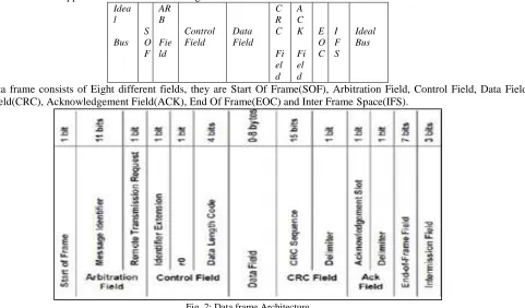
Idea l Bus S O F AR B Fie ld Control Field Data Field C R C Fi el d A C K Fi el d E O C I F S Ideal Bus
A data frame consists of Eight different fields, they are Start Of Frame(SOF), Arbitration Field, Control Field, Data Field, CRC Field(CRC), Acknowledgement Field(ACK), End Of Frame(EOC) and Inter Frame Space(IFS).
Fig. 2: Data frame Architecture
Start of Frame(SOF):
Start of frame is consisting of a single ‘dominant bit’ which only allowed to start transmission within the bus is idle. An ideal bus is detected by 11 bits consecutive sequence.
Arbitration Field(ARBF):
The Arbitration field having two components. 11-bit message identifier and 1-bit remote transmission request(RTR). This id defines the identification of particular message. Depending on the RTR bit value its gets to know the transmitted data frame is a data frame or remote frame.
Control Field(CNTF):
Data Field(DF):
The length of data field size is defined by DLC bits. Its consisting of 0 to bytes, which each contain 8 bits which are transferred MSB first. Admissible number of data bytes {0,1 ,2, 3, 4, 5, 6, 7, 8} other values may not be used.
CRC Field(CRC):
The total length of CRC field is 16 bit wide out which 15 are used to CRC sequence and 1 bit for CRC delimiter. The frame check sequence is followed up from a cyclic redundancy code. In order to carry out the CRC calculation the polynomial is considered and is to be divided (the coefficients are calculated modulo-2) by the generator polynomial. The bit stream consisting of SOF, ARBF, CNTF, DF. The remainder of this polynomial division is the CRC sequence. The CRC delimiter bit is always set as ‘recessive’.
ACK Field(ACKF):
The ACK is two bits wide and containing the ACK SLOT (ACKS) and the ACK DELIMITER (ACKD). In the ACKF the transmitter station sends two ‘recessive’ bits, a receiver which has received a valid data correctly, gives report to the transmitter by sending a ‘dominant bit during the ACKS. The ACKD second bit of ACLKF has to be a ‘recessive’ bit.
EOF Field(EOF):
Each data frame and remote frame is delimited by a sequence consisting of seven ‘recessive’ bits. Inter Frame Space(IFS):
IFS defines the minimum space between any frame of any type. During IFS no frame is node allowed to transmit any bit. Only overload signaling condition is allowed. For data frame the size of IFS is 3 bits wide.
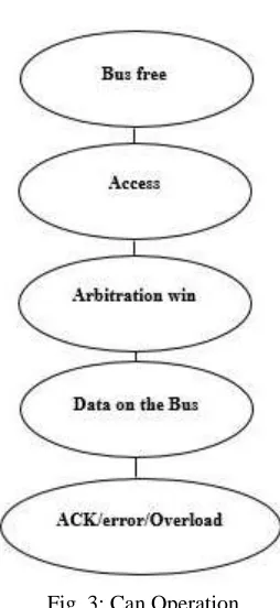
III. IMPLEMENTATION Can Operation:
Fig. 3: Can Operation
Can Environment:
Can_env having the entire top module which includes the two nodes. In one node tx0 and rx0 modules, second node having tx1 and rx1. The transmission is initiated by a switch(sw). dt is a output stores all frame bits.
Transmitter:
Can_tx_1 module contains cf(3:0) which defines the control field area. DATA_TX is the actual data to be transmitted to receiver. Upon sending data out of can_tx_1 receive an ack on ack_rx_1. Main clock clk is running with speed of 50MHz.
Receiver:
Usually in practical, receiver rate will be much greater than transmitter rate. Upon data on RX line, it receives and check for CRC calculation if generated CRC found match with transmitted CRC it accepts CAN frame else discard it. It receives the 108 data bits. The counter is used to keep a track of 108 data bits.
Board Connection:
The node 1 of TX line is connected to node 2 of RX line and node 2 of TX line is connected to node 1 of RX line. Showing the communication using Spartan 3 and Spartan 6 boards.
CAN BUS
FPGA
BOARD 1
IV. RESULTS
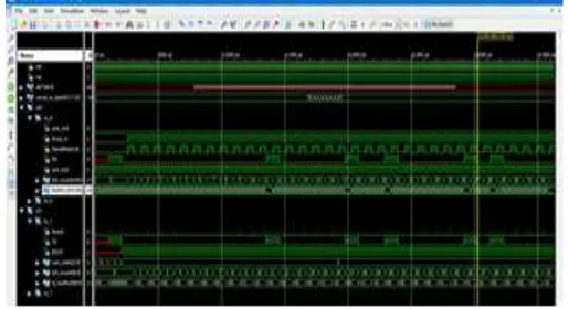
Fig. 4: Transmitter
Transmitter module wave form. It keeps a track of 100 bits by bit_conuter. The sof and eof attached and sent all data over TX line.
Fig. 5: Receiver
Receiver module receives the CAN frame on RX line. Data is received only if generated CRC at receiver end matches with a transmitter CRC. Total of 108 bits received on a track of bit counter.
Fig. 3: Transmitter and receiver
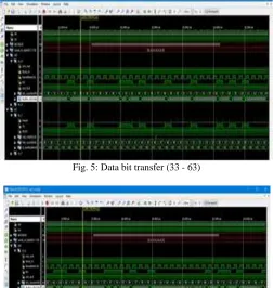
Fig. 5: Data bit transfer (33 - 63)
Fig. 6: Data bit transfer (64 - 96)
Fig. 7: Data bit transfer (96 – 108)
From figure 4 to till figure 8 shows each bit transfer. Figure 4 shows from 0 to 32 bit count. Figure 5 from 33 to 63 bit count. Figure 6 from 64 to 96 bit count. Figure 7 from 96 to 108 bit count. Figure 8 shows data field data that is A to H(64 bits).
V. CONCLUSION
CAN is a serial communication bus. CAN follow bus topology, due to which on the damage of one node block will not affect the whole network and functions in node to node or multicast message format without having to send different types of messages. CSMA/ CD + AMP allows every node to have an equal chance to access to the bus, and allows for smooth handling of collisions with AMP. CAN is ideally well suited in applications requiring a larger blocks of data with high reliability in rugged operating environments, because CAN protocol, it is message oriented and not address oriented. It is especially well suited network communication when data is needed by more than one location. All the messages being put on the bus receive every single message and acknowledge, regardless of whether in needs of data or not. Faulty nodes are automatically dropped off the bus, not allowing any one node from bringing a network down. This design work concentrates on designing of CAN IP core on FPGA using Verilog HDL. The CAN IP core working is tested in Xilinx ISE design suit 14.7 for its design, simulation with wave forms and also by using Spartan 3 XC3S200 FPGA kit and Spartan 6 XC6SLX9 FPGA kit considering them as a two nodes on the network. The switch is used at one node side to begin its transmitter action and its data frame is received at the other node of the CAN. It is observed that each bit requires 104.14 us time to send out. Also it is found that the entire one can data frame takes 11.24928 ms of time to send 108 bits starting from Start of frame bit to till end of frame bit. The important of the design part is to ensure the quality of the design to be practically reused in different applications.
VI. FUTURE SCOPE
CAN is well suited in where applications requiring a large number of short messages with high reliability in operating environments. CAN is message based and not address based, it is especially well suited when data is needed by more than one location. Bandwidth is always available for critical message transmission. To demonstrate its broadcasting feature and multi master type communication scheme, at least three CAN nodes are required. Whenever any node is added to the network it has to be configured for priority and also dynamicity of data width could be changed according to the data length code. This can be further extended for extended format which is having 29 bit of identifier makes system much more complex and flexible for operation of data access. To make system robust by including remote frames, error frame, overload frame and also bit stuffing mechanism. The designed CAN could be set to 1 Mbps to communicate with CAN modules which are available in Market.
REFERENCES
[1] CAN specifications vesion 2.0, Robert Bosch GmbH, postfach 50,D-7000 Stuttgart, Germany, 1991. [2] S. Vijayalakshmi, Vehicle control system implementation Using CAN protocol, Vol. 2, Issue 6, June 2013.
[3] Shen Ping, Wang Sujing, Wang Lide ,Liu Bin, Design and Application of Train-CAN protocol on Train Communication ICSP2008 Proceedings.. [4] Venkatesh H1, Rajashri Y Manakwad2, Venkatesh H1, Rajashri Y Manakwad2, Vol. 3, Issue 1, pp: (218-223), Month: January - March 2015. [5] Controller Area Network (CAN) Basics, AN713, Microchip Technology In
[6] Tejaswini Hulawale1, Neha Koul2, Shivang Gupta3, Fpga Based Can Protocol Controller, Volume No.03, Issue No. 01, January 2015.
[7] David D. Clark, Member, IEEE, Kenneth T. Pogran, Member, Ieee, And David P. Wed, An Introduction to Local Area Networks , Proceedings Of the IEEE, Vol. 66, No. 11, November 1978.
[8] Pierre Kleberger, Tomas Olovsson, and Erland Jonsson, Security Aspects of the In-Vehicle Network in the Connected Car, 2011 IEEE Intelligent Vehicles Symposium (IV) Baden-Baden, Germany, June 5-9, 2011.
[9] Vikash Kumar Singh#1, Kumari Archana, Implementation Of 'CAN' Protocol In Automobiles Using Advance Embedded System, Volume 4 Issue 10- Oct 2013.
[10] Abdolhamid Shorabi, FPGA Based Controller Area Network, Vol. 4, No. 2, July 2015, pp. 122~128 ISSN: 2089-4864. [11] Karl Henrik Johansson, Martin To¨rngren, Lars Nielsen, Vehicle Applications of Controller Area Network.