349 _____________________
Qusay jalil is currently pursuing master's degree program in electrical and communication engineering in University college of Engineering & Technology , Acharya Nagarjuna University, Andhra Pradesh India ,E-mail: [email protected]
Muthanna ali is currently pursuing master's degree program in electrical and communication engineering in University college of Engineering & Technology , Acharya Nagarjuna University, Andhra Pradesh, India. E-mail: [email protected]
Er. S. NagaKishore Bhavanam currently working as Assistant Professor, Department of ECE in University College of Engineering and echnology, Acharya Nagarjuna University, Guntur,India..E-mail: [email protected]
GUI Of Control System On The Level Of Oil Tank
By Two Pumps Using V. Basic
Qusay Jalil, Muthnna Ali, S Nagakishore Bhavanam
Abstract: Science is developing applications in all fields (medical, industrial, agricultural, military .... etc.) private computer applications, and at the moment has become easier development tasks through a computer, which controls the systems through th e so-called graphical user interface (GUI), where it is through the graphical interface to control the whole system in terms of operating appeared, maintenance, and other, this is not only, but rather can handle the graphical interface by any person who is not a specialist in the field of control of any It simplifies dealing with the system by the designer person.This paper represents a simplification of the work of control is full of a large volume of fuel tank system as in factories t hrough the two pumps and valves discharge , consists of control system of two parts (1- Software 2- Hardware) for Soft is the part of the compiler is responsible for receiving data , processed and giving orders to the hardware for the purpose of implementation.This is done simulations of the system through the graphical user interface GUI designed under the working environment V.BASIC by a specialist engineer to be controlled by someone less experi enced in the field of control
Index Terms: software ,hardware , GUI, pumps, valves , simulations, control system.
————————————————————
1 I
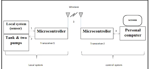
NTRODUCTIONTHe use of the programmed control system is the sophisticated modern means in the current era of systems laboratory, industrial and his goals many mismatch accuracy in work and speed in completing tasks and also can archive data easily and study the system cases ever even before five years or more one targets for the use of the system software is an abbreviation number of manpower in the production line and thus be economic benefit, either for speed control system shall be very high compared to human speed, which is slow because it depends on modern computers and high-speed and precision processors, and the most important characteristics of programmatic control system is easily diagnose faults in the concrete equipment (hardware) where they are processed and the representation of the signals (hardware) system to programmatic control through multiple transmitters movement of cases and cases of system errors or faults related to (hardware). The current control system of industrial simplified oil tank system consists respect to certain industrial facilities and two pumps are working bonding (Inter-Luc) certain programmatically. It is a personal computer all system events are presented totally invisible (Graphically) identical for (hardware) figure 1. For the purpose of facilitating the monitoring of the system by the operator cases where data
is collected and the tank pumps from the site by sensors and is sent to the system a certain protocol personal computer Thus the system is monitored cases easily. In general the project consists of four buttons (Inter-Luc) are all responsible for establishing order in the case Automatic, if that put all buttons work where there is a sign of that change color between the index case (ON) button (OFF) button of yellow to green color and this guide entry work and so the system is Automatic Bean and remove one of the buttons work be 75% of the Automatic system state in the case of two buttons to work is 50% of the Automatic and in the case of a single button and the system is 25%.The goal of segmentation buttons (tasks) responsible for the introduction of the system in the case of Automatic is for the purpose of ease of control of the system in the event of a malfunction particular regard to hardware.
Fig 1: Block Diagram of the control system on the level of oil tank by two pumps
As in the Figure above the arrow showing the direction of the data and are as follows: -
Arrow No. 1: - the data is transferred from the sensor to Micro controller.
Arrow No. 2: - to transfer data (commands) from Micro controller to the pumps.
Arrow No. 3: - data transfer (wirelessly) between the two systems of control.
350
2.1 Graphical User Interface (GUI)
VB is a Graphical User Interface (GUI) language. This means that a VB program will always show something on the screen that the user can interact with (usually via mouse and keyboard) to get a job done. The first step in building the VB program is to get the GUI items on the screen. This is done via pull-down menus that list the available graphical objects. Every system is slightly different but, generally speaking, left-clicking on an object allows you to describe attributes like size and position. Right clicking allows you to write code. For example, if the GUI item is a switch, left-clicking would allow the programmer to say how big the switch was, how it was labeled and where on the screen it is positioned. Right-clicking on the switch would bring up a window that allows the programmer to write the code that describes what happens when the user clicks the switch.
2.2 Overview of User Interface Software Tools
Since user interface software is so difficult to create, it is not surprising that people have been working for a long time to create tools to help with it. Today, many of these tools and ideas have progressed from research into commercial systems, and their effectiveness has been amply demonstrated. Research systems also continue to evolve quickly, and the models that were popular five years ago have been made obsolete by more effective tools, changes in the computer market, and the emergence of new styles of user interfaces such as handheld computing and multi-media.
2.3 Components of User Interface Software
As shown in Figure 2, user interface software may be divided into various layers: the windowing system, the toolkit and higher-level tools. Of course, many practical systems span multiple layers. The windowing system supports the separation of the screen into different (usually rectangular) regions, called windows. The X system [Scheifler 1986] divides the window functionality into two layers: the window system, which is the functional or programming interface, and the window manager, which is the user interface. Thus, the window system provides procedures that allow the application to draw pictures on the screen and get input from the user, and the window manager allows the end user to move windows around, and is responsible for displaying the title lines, borders and icons around the windows. However, many people and systems use the name ―window manager‖ to refer to both layers, since systems such as the Macintosh and Microsoft Windows do not separate them. This article will use the X terminology, and use the term ―windowing system‖ when referring to both layers
Figure 2 The components of user interface software
3 R
ESULTSThe program consists of simulations for a simplified control system to the simple user, as shown figure 3
Figure 3 Final GUI of control system on the level of oil tank by two pumps using v.basic.
This system consists of two pumps are with the following status as shown in the figure below:
Figure-4-a Figure-4-b
When the color of pump is green this mean the pump is switch off as shown in the figure-4-a , but when the color of the pump is yellow this mean the pump is switch on as shown in the figure 4-b. The discharge valve has the following status as shown in the figure-5- below:
Figure-5-a Figure-5-b
When the color of valve is green this mean the valve is closed as shown in the figure-5-a , but when the color of the valve is yellow this mean the valve is open as shown in the figure-5-b. the control board of each pump as shown in the figure below:
351
Figure-6-a Figure-6-b
The control board for pump-A as shown in the FIGURE-6-a and the control board for pump-B as shown in the FIGURE-6-b , this control board is used to switch on and switch off the pumps and can change the mode of the pumps , There are three modes of operation: Repair, Reserve and work mode explain each one:
Repair mode: In the case of pump damage must be converted it to this mode, this mode give order to disconnect the main electrical power that Feeder for the pump by using Relay In order to avoid electrical shock when a Perform the Repair process.
Reserve mode: this mode is transferred pump to a reserve that mode is working with interlock < Levelof oil tank with this mode when the level reach to 75% the interlock give command to switch off the reserve pump and stay only one pump that has work mode .
The control board of the valve can open and close the valve as shown in the figure-7 below:
Figure-7
There are three alarm signals this working as flash To alert the operator from some events as following:
FIGURE-8-a FIGURE-8-b FIGURE-8-c
If the empty signal alarm appear that mean the level below than 5% shown in the figure-8-a and this alarm signal will disappear when the level increase more than 5%, the full signal alarm this signal will appear when the level increase above 90% shown in the figure-8-b and disappear when the level decrease less than 90% , the over flow signal is appear when the level increase to 100% and switch on the one or two
pumps shown in the figure-8-c and this alarm signal will disappear when switch of the pumps. It possible the two alarm signals full and over flow simultaneously. When use the real operation the figure-9 below will appear when the cable of interfacing is not connected and disappear if the cable is connected
FIGURE-9
There are four automatic interlocks , it can switch on and switch off the interlock by using the columns OFF and ON , when need to switch off the interlock press button OFF the shape color between the OFF and ON column is change to yellow ,but if want to switch on the interlock then press the ON button the shape color between the OFF and ON column is change to green , else the third interlock doesn‘t have button but can switch on it by change the mode for one pump to work mode and another to reserve mode then the interlock will switch on and the color change to green. for example the interlock > Level Of Oil Tank is switch off as shown in the FIGURE-10-a and switch on as shown in the FIGURE-10-b
FIGURE-10-a
FIGURE-10-b
The first column OP refer to execution status of the interlock if the color is green that mean the interlock not execute (normal) but if the color is change to red that mean the interlock execute the automatic state and give some events will explain next, if the interlock is switch off then the interlock will not execute automatic state never , the four automatic interlocks are:
> Level Of Oil Tank : when this interlock is switch onand the level increase to 100% then the OP will change to red color as shown in the FIGURE-11 :
FIGURE-11
This interlock will execute the two automatic states: 1-Switch off the working pumps.
352 FIGURE-12-b
FIGURE-12-a FIGURE-12-b
< Level Of Oil Tank: : when this interlock is switch onand the level decrease less than 100% then the OP will change to red color as shown in the FIGURE-13 :
FIGURE-13
This interlock working with Reserve Pumps interlock , if the Reserve Pumps interlock is switch on and the level decrease less than 75% the interlock will execute the automatic states:
1-switch on the two pumps .
2- generate disable button state to avoid switch off pumps manually by control board to full the tank , the switch off button change to red color as shown in the FIGURE-14-a and FIGURE-14-b
3- if the level reach to 75% the interlock will switch off the Pump that has Reserve mode and the pump that has work mode continuous in work until the interlock > Level Of Oil Tank will switch off it when full the tank.
4- when the level is 100% the interlock > Level Of Oil Tank will switch off the pumps and when the level decrease less than 100% the interlock < Level Of Oil Tank will not switch on the pumps until the level decrease less than 95% this as protection for the pumps to avoid the oscillation state which mean fast switch on and switch off the pumps at critical point of the level.
FIGURE-14-a FIGURE-14-b
Reserve Pumps: can switch on the Reserve Pumps interlock by change the one of the pump to work mode and the another to reserve mode then the interlock is active and the color of shape at the third column will change to green as shown in the FIGURE-15-a else this state the interlock will switch off thus the color will change to yellow as shown in the FIGURE-15-b
below:
FIGURE-15-a
FIGURE-15-b
If this interlock is switch on then the interlock < Level Of Oil Tank will switch on the two pumps if the level decrease less than 75% and switch off the reserve if the level increase more than 75% , But if the interlock Reserve Pumps is switch off the interlock < Level Of Oil Tank will switch on the two pumps if the level decrease less than 75% and will not switch off the reserve if the level increase more than 75% this is a main difference between the interlock Reserve Pumps is switch on or switch off.
Valve: when this interlock is switch on then generate disable button as shown in the FIGURE-16 to avoid open the valve through the system in operating status , and change the OP color to red as shown in the FIGURE-17.
FIGURE-16
FIGURE-17
but remove the disable button automatically when the system in Repair status that mean if the tank or pumps are damage then must change the two pumps to Repair mode to disconnect the electrical power that feeding the pumps by give order to switch off the Relays, just transfer to the repair mode the system give an order to disconnect the relays , and active the button then can open and close the valve manually to discharge the level and perform the repairing process.
4
C
ONCLUSION353 where the pumps are electricity from three phase and this
shows that the high-capacity system is not easy to control them programmatically. Through the programming has to mind the technical specifications that are high-capacity and voltages and when access level to 100%, the program to shut down and is not running, one at each access level to 95% to avoid frequent operating condition in a short time (oscillation) of the pumps at the critical point of the level, so as to give sufficient time to turn off the pump for the purpose of getting rid of high-temperature formed in files by the primitive stream which is very high at the beginning of operating the pump and this in turn works to protect the pumps from damage files.
R
EFERENCE[1] Hicks, F., Tyler, G.; & Edwards, T.W. (1971), ‗Pump Application Engineering‘. McGraw-Hill Book Company, New York.
[2] Khaled Reza, S.M., Shah Ahsanuzzaman Md. Tariq, S.M. Mohsin Reza (2010), ‗Microcontroller Based Automated Water Level Sensing and Controlling: Design and Implementation Issue‘. Proceedings of the World Congress on Engineering and Computer Science, pp 220- 224.
[3] Venkata Naga Rohit Gunturi (2013), ‗Micro Controller Based Automatic Plant Irrigation System‘, International Journal of Advancements in Research & Technology, Vol. 2, Iss. 4, ISSN 2278-7763
[4] Judy Hodgson, Trey Walters(2002), ‗Optimizing Pumping Systems To Minimize First Or Life-Cycle Cost‘, Proceedings of the 19th international pump users symposium. Pp 1-8.
[5] Rojiha, C. (2013), ‗Sensor Network Based Automatic Control System for Oil Pumping Unit Management‘, International Journal of Scientific and Research Publications, Vol. 3, Iss. 3. Pp 1-4.
[6] P. Dietz, W. Yerazunis, D. Leigh, Very Low-Cost Sensing and Communication Using Bidirectional LEDs, UbiComp 2003: Proceedings, vol. 2864, pp. 175-191, 2003.
[7] M. Javanmard, K.A. Abbas and F. Arvin, ―A Microcontroller-Based Monitoring System for Batch Tea Dryer‖, CCSE Journal of Agricultural Science, Vol. 1, No. 2, December 2009
[8] Roderick L. Shepherd, William S. Yerazunis and Senior Member, ―Low-Cost Surface Mount LED Gas Sensor‖, IEEE King Tong Lau and Dermot Diamond, Sensors-00997, 2005
[9] T. S. Aye, and Z M. Lwin, ―Microcontroller Based Electric Expansion Valve Controller for Air Conditioning System‖, World Academy of Science, Engineering and Technology, 2008
[10] L. Byrne, K.T. Lau, and D. Diamond, Monitoring of headspace total volatile basic nitrogen from selected fish species using reflectance spectroscopic
measurements of pH sensitive filmsî, The Analyst, vol. 127, pp. 1338-1341, 2002.
[11] Milenkovic, A., Milenkovic, M., Jovanov, E., Hite, D., and Raskovic, D.: An environment for runtime power monitoring of wireless sensor network platforms, Proc. of SSST‘ 05, 406–410, 2005.
[12] E.J. Cho and F.V. Bright, Integrated chemical sensor array platform based on light emitting diode, xerogel-derived sensor elements, and high-speed pin printing, Analytica Chimica Acta, vol. 470, pp. 101-110, 2002.