RECTENNAS DESIGN,
DEVELOPMENT AND APPLICATIONS
*
Rakesh Kumar Yadav, **Sushrut Das and *R. L. Yadava,
*
Department of Electronics & Communication Engineering, GCET, Gr. Noida, U. P., India
**
Department of Electronics Engineering, Indian School of Mines, Dhanbad, Jharkhand, India
ABSTRACT
The present paper describes the development of rectenna in terms of its applications in Microwave
Power Transmission, Harmonic Rejection, CP radiation and ISM band. These rectennas consist of several
antennas such as dipole, antenna arrays, slot meander line and rhombic loop antennas along with the rectifying diodes. In some cases more than one rectifying devices have also been used and antenna is found to be act at dual bands. It has also found that rectenna reject the harmonics upto 3rd order and enhanced the performance characteristics. The maximum efficiency about 91% with 1.2 W of input power has been observed if the rectenna is used for microwave transmission.
KEYWORDS:
Rectenna, Conversion Efficiency, Band Reject Filter, Voltage Standing Wave Ratio, Industrial-Scientific-Medical Band, Microwave Power Transmission.
I. INTRODUCTION
The rectenna has been a growing area of research in recent years, as the microwave integrated circuit and monolithic microwave integrated circuit technologies became more mature allowing for high level integration. The rectenna termed as rectifying antenna, is combination of an antenna and a nonlinear rectifying element (Schottky diode, IMPATT diode…etc.) where the two elements are integrated into a single circuit. The schematic of a rectenna system is shown in Fig. 1. Such a system is capable to receive and detect microwave power and converts the RF power into dc voltage at high frequencies (THz).
Fig.1 Schematic rectenna system.
Since the rectenna is a receiving module collecting power from a radiation field, its sensitivity is defined by
=
ℎ
Division of this value with the effective antenna aperture leads to the normally used quantity for detectors.
=
This characterizes the nonlinear element with its matching.
distributed. Such power distribution is achieved by the dispersive nature of microwave energy in space, eliminating the need for physical interconnects to individual load elements.
The “rectenna” was invented by Brown and has been used for various applications such as the microwave power helicopter and the receiving array for Solar Power Satellite [1-5]. The experiment on the microwave powered aircraft which was conducted in Canada under the project SHARP (Stationary High Altitude Relay Platform), in which the structure of rectenna was evolved from a bulky bar-type to a planar thin-film type. It was found that the weight to power output ratio reduces effectively, and the power conversion efficiency of 85% is observed at 2.45 GHz [6, 7].
In general it is difficult to predict how the rectenna system is optimized for the maximum conversion efficiency. However, there are several theoretical methods to overcome this problem. These methods can be divided into two groups; the first one is to directly simulate the rectenna circuit in time domain [8], whereas the other is to find a closed-form equation which can explain the relationship between diode parameters and the conversion efficiency [9-10]. All these studies were done on 2.45GHz because it is not strongly attenuated by the atmosphere even under a severe weather condition [11]. The frequency 2.45 GHz is suitable for the application of power transmission between ground-to-ground, ground-to-space and space-to-ground. However, the operating frequency can be increased to allow power transmission for the space-to-space application, over much longer distances with the smaller antenna and rectenna. Fig. 2 shows the plot of rectenna conversion efficiency with the input power.
Fig. 2 General relationship between microwaves to dc power conversion efficiency and input power.
The main objective with the design of rectenna is to obtain high conversion efficiency, and there are two approaches to achieve this goal. In first maximum power is collected and delivered to the rectifying diode, while in the second one harmonics generated by the diode are suppressed, which re-radiate from the antenna as power lost. In order to increase conversion efficiency by the first method, several broadband antennas, large antenna arrays and circularly polarized antennas have been designed and experimented. The broadband antenna enables relatively high RF power to be received from various sources while the antenna array can increase incident power delivered to the diode by enlarging antenna aperture and antenna gain. Antenna array is an effective means to increase the receiving power for rectification. However, a trade-off arises between the antenna size and the radiation gain. The circularly polarized antenna offers power reception with less polarization mismatch. However in second method, the rectenna consist of an LPF between the antenna and the diode, as well as an additional LPF on the dc output side of the diode. The main reason for the rise in the efficiency was the improvement in the diode and circuit construction for high input power levels.
II. MICROWAVE POWER TRANSMISSION
The receiving rectifying antenna (rectenna) is one of the main components of microwave power transmission systems. In order for such systems to operate cost efficiently in land or spaced-based locations, the conversion efficiency from microwave to dc of the rectenna must be high. In year 1992, J.O. Mcspadden, T. Yoo and K. Chang designed a 35 GHz rectenna using a microstrip patch antenna and 29% of measured efficiency was found with 120 mW input power. The measured efficiency versus input power for a 100Ω load resistance is shown in Fig.3.
Fig. 3 The power conversion efficiency of the 35 GHz rectenna measured with the waveguide array simulator.
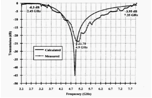
They also designed a frequency selective surface using an equivalent circuit model and tested to pass 2.45 GHz with insertion loss of 0.3 dB [12]. It also rejects the second harmonic of 4.9 GHz. The frequency response of the gridded square FSS array is shown in Fig. 4. The 10 dB of attenuation occurred at 4.9 GHz on a small rectenna array whereas the conversion efficiency was decreased by less than 1%.
Fig. 4 Calculated and measured frequency response of the gridded square FSS array.
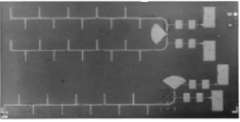
Fig. 5 Photo of the microstrip rectenna. (a) Two branches antenna with two Schottky diodes in series (b) Antenna with single diode
Fig. 6 Output voltage of the rectenna/CMOS MCM versus frequency (S = 4.7 µW/cm2)
Fig.7 H-plane radiation pattern of the packaged rectenna/CMOS module.
Fig. 8 Output voltage for a rectenna panel with load chosen to maximize activator voltage while minimizing the transmit power needed.
However, J.A.G. Akkermans et al. proposed low cost rectenna for low power application, shown in Fig.9. The main design parameters of the rectenna considered; are dimensions and conversion efficiency which is defined as
=
(1)The main component of the rectifying circuit is Schottky diode, which has voltage current characteristics defined by;
=
1
(2)And during stationary operation the current through the nonlinear diode is
=
∑
cos nω t
sin nω t
(3)
The coefficient and can be found out by minimizing the square of the error Ɛ between and over one period of time T.
Ɛ=
=
1 0 ℎ (4)The coefficient can be found via a multi-dimensions minimization method. This allow for a fast design of rectenna system. To acquire small area a layered design is proposed. They found a 40% of conversion efficiency [15].
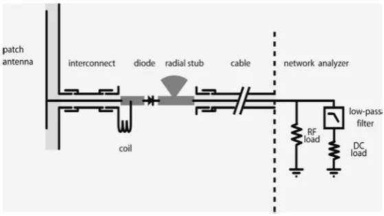
B. Essakhi, L. Pichon and G. Akoun [16] proposed a computationally efficient model of a broadband microwave rectenna. The rectenna with RF to dc circuit is shown in Fig. 10. They calculated the impedance of antenna over a wide frequency band by the 3D FEM and Pade approximations methods. Then an equivalent circuit was designed. The resulting equivalent circuit of antenna together with lumped component of rectenna (diodes and loads) has been incorporated into PSPICE. Such an approach provides a significant improvement at the design stage of a rectenna in the framework of microwave power transfer.
Fig. 10 Rectenna with RF-to-dc circuit
However, N. Shinohara and H. Matsumoto proposed a 3.2 m x 3.6 m rectenna array consisting of 256 sub-arrays where each of the sub-sub-arrays has 9 rectenna elements connected in parallel [17].They tested two different arrays, one is an array placing the high efficiency sub array in the central area of the array and other is non arranged and found that arranged array provides 46% higher dc maximum output. They checked dependency of rectenna array characteristics on the electrical connection with 5 different methods as shown in Table I and found that the differences of the output dc power is within 5%. The findings are useful for construction of large rectenna array.
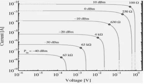
However in 2004, J. A. Hagerty et al. [18] designed a 64 element dual CP spiral rectenna array over a frequency range of 2-18 GHz with single tone and multi tone incident waves. The integration of antenna and rectifier, using full wave electromagnetic field analysis and harmonic balance nonlinear circuit analysis gives a compact design because it eliminates matching and filtering circuit. Fig. 11 shows an equiangular spiral antenna with a packaged Schottky diode. The ambient RF power levels vary by several orders of magnitude, implying a varying dc load as reflected in the I-V characteristics of single rectenna element as shown in Fig. 12. The applications of proposed rectenna are wireless powering of industrial sensors and recycling of ambient RF energy.
Fig. 12 Simulated I–V curves as a function of load resistance and input RF power to the diode. The peaks in rectified power are indicated by circles with the corresponding optimal load resistance.
III. HARMONIC REJECTION
A rectenna having the property of harmonic rejection eliminates the requirement of LPF between the antenna and diode. In this way, additional insertion loss at the fundamental frequency associated with the LPF in a conventional system can be eliminated to produce higher efficiency. A.Georgiadis, G. Andia, and A. Collado proposed a methodology to design a rectenna utilizing reciprocity theory and combining electromagnetic (EM) simulation and harmonic balance (HB). They designed a 2.45 GHz rectenna, based on a square aperture-coupled patch antenna with dual linear polarization and found that by etching a cross shaped slot on the patch surface, the size of patch is reduced by 32.5% [19]. The circuit is optimized for low input power densities and a maximum efficiency of 38.2% at a load of 6.2 KΩ was achieved for 1.5 uWcm-2 input RF power densities at 2.43 GHz as shown in Fig. 13. The dependency of the efficiency on the load at 2.45 GHz is shown in Fig. 14 and gives the optimum load value of 4.5 K Ω.
Fig. 13 RF-to-dc efficiency versus frequency (RL= 6.2 KΩ)
Fig. 14 RF-to-dc efficiency versus load impedance (f = 2.45 GHz).
Fig. 15 Block diagram of the conventional and the proposed rectennas.
Fig. 16 Measured return losses of the microstrip circular sector and square patch antennas.
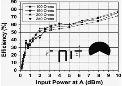
Fig.17. Efficiency versus input power at A with four variable resistor values.
J. Y. Park, S. M. Han and T. Itoh [20] proposed a rectenna designed with a microstrip harmonic rejection circular sector antenna at 2.4 GHz. A typical rectenna is shown in Fig. 15. The circular sector antenna with a sector angle of 240° and an inset feeding point at 30° from the edge avoids the radiations of harmonics. Thus low pass filter which cause insertion loss for the fundamental frequency can be eliminated. Fig. 16 shows that return loss at 2nd and 3rd harmonics of circular sector antenna are very high. Therefore high efficiency rectenna can be designed having maximum conversion efficiency of 77.8% using a 150 Ω load resistor as shown in Fig. 17.
IV. CIRCULARLY POLARIZED
rectenna with two unbalanced circular slots and 2nd order harmonic rejection property [21]. It operated at 2.45 GHz with measured BW of 137 MHz and minimum 1.5 dB AR. The used double rectifier gives 78% of RF to dc conversion efficiency at 16.5 mW/cm2 incident power density and 1 K Ω load resistance while the optimum DC voltage output is 15.8 V. The double output voltage is generated by storing change at series capacitor Cs during negative phase of RF signal through the shunt diode while change in Cs is accumulated with input potential during positive signal by turning on the series diode. The rectenna can provide good efficiency of 53% and 75% in uncontrolled and controlled environment respectively. The doubler layer configuration and circular slot structure make the rectenna much small (12% of size reduction) and compact (2.4 mm in thickness).
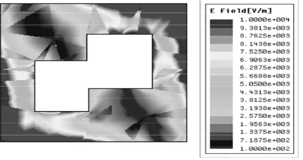
M. Ali, G. Yang and R. Dougal [22] proposed a CP microstrip patch antenna that can be used either WLAN antenna in the 5.15-5.35 GHz or as a rectenna at 5.5 GHz. The wide axial ratio BW can be achieved by two rectangular slot positioned along the diagonal of square patch antenna which also create two hybrid operating mode that is very close in frequency. A12.4% returns loss BW, 12.1% of axial ratio BW and 57.3% of conversion efficiency for a load of 300 Ω can be achieved. Computed E field of proposed antenna is shown in Fig.18.
Fig. 18 Computed E field distribution of the proposed antenna on 175-mm-thick Duroid 5880 substrate at 5.5 GHz
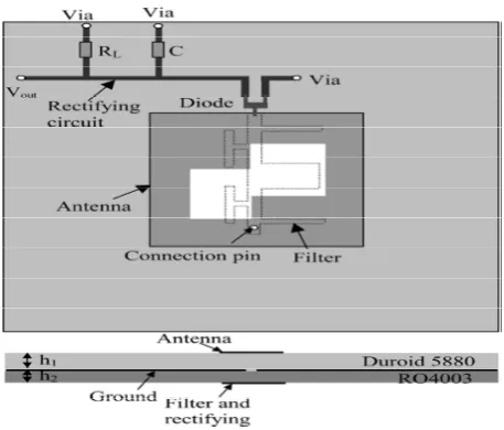
They also designed a miniature CP rectenna operating at 5.5 GHz in year 2006, which reduces out of band harmonic emission with the help of integrated BRF and schematic is shown in Fig. 19. The conversion efficiency of the CP rectenna is given by
=
(5)Where;
= Transmit Power; = Gain of rectenna
= Gain of the Transmitting Antenna
Fig. 19 Miniature rectenna with filter
The output voltage and conversion efficiency of this rectenna are shown in Fig. 20. It has a conversion efficiency of 74% with more than 50 dB out of band harmonic suppression at 11 GHz, therefore can be used for data communication with 5.15-5.35 GHz [24].
Fig. 20 Measured output voltage (a)VD versus distance and (b) Conversion efficiency versus power density at 5.5 GHz.
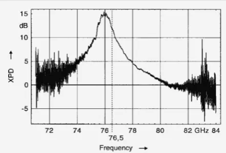
Fig. 21 Measured XPD of the CP receiver chip versus frequency.
V. HIGH EFFICIENCY
B. Strassner and K. Chong [25] proposed a new CP high gain high efficiency rectenna array designed in a coplanar stripline circuit. And found that each antenna has a CP gain of 11 dB and better than 1 dB axial ratio fractional BW of 4.7%. The single element antenna uses a CPS band reject filter to suppress the reradiated harmonic by more than 19 dB and achieve 81% RF to dc conversion efficiency at 5.71 GHz. Whereas 3 x 3 rectenna array produces 0.86 W of dc output power with an RF to dc conversion efficiency of 78% and an axial ratio of 0.25 dB for an incident CP power density of 7.6 mW/cm2 at 5.61 GHz. The measured RF to dc conversion efficiency of single element rectenna and array at 5.71 and 5.61 GHz respectively are shown in Fig. 22 and Fig. 23.
Fig. 22 Measured single element rectenna efficiency curves at 5.71 GHz and d = 10 mm for 50 incremental loading. Calculated curves are shown for the 50 and 200 loading.
Fig. 23 Array RF-to-dc conversion efficiency versus CP power density at 5.61 GHz for various array loading (R ).
RF to dc conversion efficiency for dual frequency antenna which shows that the conversion efficiency at free space is 84.4 and 82.7% at 2.45 and 5.8 GHz respectively is shown in Fig. 24.
(a)
(b)
Fig.24 RF-to-dc conversion efficiency for dual-frequency rectenna. (a) Efficiency and dc output voltage versus received power. (b) Efficiency versus power density.
J. O. Mcspadden, L. Fan and K. Chang [27] designed a high efficient rectenna element, in which operation of antenna element can be better understood by analyzing the diode dc characteristics with an impressed RF signal. They used a silicon Schottky barrier mixer diode with a low breakdown voltage as the rectifying device and it was found that the RF to dc conversion efficiency of 82% at an input power level of 50 mW and 327 Ω load. The diode junction waveform can be expressed as
=
cos
(6)
=
.
.
(7)Where;
= Output self bias dc voltage across the resistive load. = Peak voltage of the incident microwave signal.
The forward bias turn on angle θon is a dynamic variable dependent on the diode’s input power and is given
by
Where; and are the diode series and load resistance. The antenna has good impedance matching and VSWR is less than 1.3. The power level is 21 dB down from the fundamental input power at 2nd harmonics. The proposed rectenna found very useful at 5.8 GHz for application involving MPT.
VI. DUAL FREQUENCY
With the usage of multiple frequency bands in wireless communication systems, some dual-frequency rectenna have been developed. In these designs, the antenna elements usually have a dimension of one wavelength length or even more.Y. J. Ren, M. F. Farooqui and K. Chang proposed a novel dual frequency rectifying antenna operating at 2.45 and 5.8 GHz [28]. Rectenna consists of two compact ring slot antenna, a hairpin LPF and a rectifying circuit. By using meander line structure in annual slot ring antenna, the size reduction upto 52% was observed, whereas 2nd and 3rd harmonics of both operating frequency was suppressed by hairpin filter. It was found that the Rectenna has gain of 2.19 and 3.6 dBi while RF to dc conversion efficiency of 65% and 46% at 2.45 and 5.8 GHz respectively when power density is 10Mw/cm2.
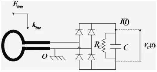
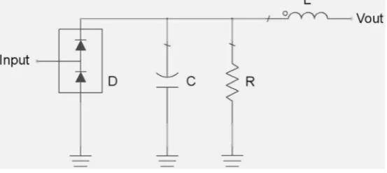
However, J. Heikkinen and M. Kivikoski proposed a novel dual frequency CP shorted ring slot antenna for WPT at 2.45 and 5.8 GHz. It was composed of two nested microstrip fed shorter annular ring slot antenna and two rectifier circuits. The circuit diagram of rectifier is given in Fig. 25 while component values are summarized in Table.2. At a maximum distance of 2 m, output dc voltage of over 2 V at the lower frequency band and over 1 V at the higher frequency band can be achieved [29]. It was also found that the axial ratio of 2.2 Db in lower band while 1.3 Db in higher band as shown in Fig. 26.
Fig. 25 Circuit diagram of the rectifier circuit.
TABLE II
Fig. 26 Upper graph: output dc voltage and axial ratio of the low-band rectenna. Lower graph: output dc voltage and axial ratio of the high-band rectenna.
T. W. Yoo and K. Chang [30] proposed a rectenna with 39% conversion efficiency at 35 GHz and found that 60% conversion efficiency can be achieved at 10 GHz by using a microstrip dipole antenna and mixer diode, as shown in Fig. 27.
Fig. 27 10 GHzto dc conversion efficiency of a Ka-band diode measured with 120 Ωdc load.
VII. ISM FREQUENCY 5.8 GHz
Y. J. Ren and K. Chong proposed two new CP retro directive rectenna array having a 2x2 array and 4x4 arrays [31]. They used a proximity coupled microstrip ring antenna as the array element, which can block signals upto 3rd order harmonics from reradiating by the rectifying circuit and thus no BPF required. It has CP gain of 5.89dB and an AR of 1.7dB. At the broadside, 73.3% and 55% conversion efficiency for 2x2 and 4x4 rectenna array has found for 10mW/cm2 incident power density. The dc output voltage is 2.48 and 8.59V respectively and almost constant within ±10° of the incident angle. This technique is very suitable for the WPT with a high gain, but narrow beam width transmitting antenna.
Fig. 28 Measured dc output voltages of the dual-diode and single-shunt diode rectennas.
Fig. 29 Measured dc output voltage of the rectenna array.
C. H. K. Chin, Q. Xue and C. H. Chan proposed a novel finite ground coplanar waveguide high gain rectenna element having conversion efficiency of 68.5% at 5.8 GHz with an input power of 18 dBm [33]. The antenna used for this rectenna has the similar characteristics as of the two element array. It generates a similar radiation pattern but radiates a higher gain of 9 dBi. It was found that the compact CPW resonant cell (CCRC) which is used as an input band stop filter, effectively suppress the 2nd harmonic radiation. It was also found that by using CCRC the RF to dc conversion efficiency is enhanced by 6% with a 270 Ω load resistance.
J. Heikkinen and M. Kivikoski [34] proposed a novel CP shorted annular ring slot rectenna on a 0.5mm thick flexible microwave laminate. And found that output dc voltage of 1.3V and axial ratio is 1.5dB for 32 dB microwave power transmission over a distance of 2m at 5.8 GHz. Measured rectifier and rectenna output dc voltage are plotted in Fig. 30 and Fig. 31. This rectenna is useful as a ’virtual battery’ where the receiver is rotating relative to the transmitter.
Fig. 31 Measured rectenna output dc voltage (Vout) and axial ratio at two different transmission distances and transmitted power levels (Pt).
B. Strassner and K. Chang proposed a new CP high gain, high efficiency rectenna which can be rotated and still maintain a constant dc output voltage. A Schottky diode is used and with this the RF to dc conversion of 80% with input power of 100mW and a load resistance of 250Ω can be achieved [35]. It was found that a high gain dual rhombic loop antenna and a reflecting plane are used to achieve a CP gain of 10.7 dB and a 2:1 VSWR BW of 10%. The CP gain of the proposed rectenna is given as
=
(9)Where,
-Linearly polarized gain.
Gain correction factor (GCF) =
20
√ . (10)
The rectenna pattern has an elliptical cross section with orthogonal beam width of 40° and 60°. It has coplanar stripline BRF which suppress the reradiated harmonics by 20 dB. The measured diode efficiency and output voltage verses input power for various loads are shown in Fig.32.
Fig. 32 Directly measured diode conversion efficiency and output voltage versus power delivered to the diode for various load resistances.
Fig. 33 Return loss for DRLA + filter + balun
(a)
(b)
Fig. 34 Measured DRLA + filter + balun circuit axial ratio: (a) versus frequency and (b) versus incident angle.
Fig. 35 RF-to-dc conversion efficiency for various resistive loading.
impedance dipole is shown in Fig.36. It was found that a maximum conversion efficiency of 76% at 5.8 GHz with a load of 250Ω can be achieved. It was also found that the conversion efficiency from 5.725 to 5.875 GHz range is better than 67%, which cover the entire 5.8 GHz ISM band.
Fig.36 Configuration of the compact 5.8-GHz rectenna using a Stepped impedance dipole.
VIII. CONCLUSION
Therefore paper describes the progressive development of rectenna in terms of its applications in various fields; Microwave Power Transmission, Circularly Polarized Radiation, High Efficiency and Dual Frequency characterstics in the range of ISM as well as other high frequency bands.Theproposed rectennas comprising several antennas such as dipole, arrays, slot, meander line, annular ring and rombhic loop antennas along with a rectifying diode. In some cases more than one rectifying devices have also been used which causes the dual band operations and better efficiency. The maximum efficiency as microwave power transmission was found to 91 % with 1.2 W of input power while in case of harmonic rejection, rectenna designed with circular sector antenna provides conversion efficiency of 77.8 % with 150 Ω load and very high return loss at 2nd and 3rd harmonics.The RF to dc conversion efficiency for circularily polarized is 78% at 16.5 mW/cm2 incident power density while in case of dual frequency the RF to dc conversion efficiency of 65% and 46% are achieved at 2.45 GHz and 5.8 GHz respectively when power density is 10mW/cm2.
REFERENCES
[1] W. C. Brown et al., U.S. Patent 3 434 678, Mar. 25, 1969.
[2] W. C. Brown, “Experiment in the transport of energy by microwavebeam,” in IEEE Inr. Conv. Rec., vol. 12, pt. 2, Mar. 1964, pp. 8-18.
[3] ---, “Experiments involving a microwave beam to power and position a helicopter,” IEEE Trans. Aerosp. Electron. Syst., vol. AES- 5, no. 5, pp. 692-702, Sept. 1969.
[4] --- , “Solar Power Satellite Program Rev. DOE/NASA SatellitePower System Concept Develop. Evaluation Program,” Final Proc. Conf. 800491, July 1980.
[5] W. C. Brown, “The history of power transmission by radio waves,”IEEE Trans. Microwave Theory Tech., vol. MTT-32, pp. 1230– 1242,Sept. 1984.
[6] J. Schlesak, A. Alden and T. Ohno, “A microwave powered high altitude platform,” in IEEE MTT-S Int. Microwave Symp. Dig., 1988, pp. 283-286.
[7] W. C. Brown, “Performance characteristics of the thin-film, etched circuit rectenna,” in IEEE MTT-S Int. Microwave Symp. Dig., 1984,pp. 365-367.
[8] J. J. Nahas, “Modeling and computer simulation of a microwave-to-dc energy conversion element,” IEEE Trans. Microwave Theory
Tech., vol. 23, no. 12, pp. 1030-1035, Dec. 1975.
[9] W. C. Brown and E. E. Eves, “A microwave beam power transferand guidance system for use in an orbital astronomy support facility,” Final Report (Phase 11) to NASA, NAS-8-25374, Sept. 1972.
[10] G. P. Boyakhchyan et al.,“Analytical calculation of a high-efficiency microwave rectifier employing a Schottky-barrier diode,”
Telecom. Radio Engin. (English Translation of Elaktrosvyaz, and Radiotekhnika) vol. 37-38, no. 10, pp. 64-66, Oct. 1983.
[11] W. C. Brown, “All electronic propulsion key to future space ship design, ” presented at AIAA/ASME/SAE/ASEE 24th Joint Propulsion Conf., Boston, July 1988.
[12] James O. McSpadden, Taewhan Yoo and Kai Chang, “Theoretical and Experimental Investigation of a Rectenna Element for Microwave Power Transmission,”IEEE Trans. Microwave Theory Tech., vol. 40,no. 12, pp. 2359-2366, (1992).
[13] Karl M. Strohm, Josef Buechler, and Erich Kasper, “SIMMWIC Rectennas on High-ResistivitySilicon and CMOS Compatibility,”
IEEE Trans. Microwave Theory Tech., vol. 46,no. 5, pp. 669-676, (1998).
[14] Larry W. Epp, Abdur R. Khan, Hugh K. Smith and R. Peter Smith, “A Compact Dual-Polarized 8.51-GHz Rectenna for High-Voltage (50 V) Actuator Applications,” IEEE Trans. Microwave Theory Tech., vol. 48,no. 1, pp. 111-120, (2000).
[15] J. A. G. Akkermans, M. C. van Beurden,G. J. N. Doodeman, and H. J. Visser, “Analytical Models for Low-Power Rectenna Design,”
[16] B. Essakhi, L. Pichon, and G. Akoun, “Fast Analysis of a Broad-Band Microwave RectennaUsing 3-D FEM and Padé Approximation,”IEEE Trans. Magnetics, vol. 43,no. 4, pp. 1309-1312, (2007).
[17] Naoki Shinohara and Hiroshi Matsumoto, “Experimental Study of Large Rectenna Array for Microwave Energy Transmission,” IEEE
Trans. Microwave Theory Tech., vol. 46,no. 3, pp. 261-268, (1998).
[18] Joseph A. Hagerty,Florian B. Helmbrecht,William H. McCalpin, Regan Zaneand Zoya B. Popovic, “Recycling Ambient Microwave Energy With Broad-Band Rectenna Arrays,”IEEE Trans. Microwave Theory Tech., vol. 52,no. 3, pp. 1014-1024, (2004).
[19] A. Georgiadis, G. Andia and A. Collado, “Rectenna Design and Optimization Using Reciprocity Theory and Harmonic Balance Analysis for Electromagnetic (EM) Energy Harvesting,” IEEE Antennas and Wireless Propogation Letters, vol. 9, pp. 444-446, (2010).
[20] Ji-Yong Park, Sang-Min Hanand Tatsuo Itoh, “A Rectenna Design With Harmonic-Rejecting Circular-Sector Antenna,” IEEE
Antennas and Wireless Propogation Letters, vol. 3, pp. 52-54, (2004).
[21] Tzong-Chee Yo, Chien-Ming Lee, Chen-Ming Hsu, and Ching-Hsing Luo, “Compact Circularly Polarized Rectenna With Unbalanced Circular Slots ,” IEEE Trans. Antennas Propagate., vol. 56,no. 3, pp. 882-886, (2008).
[22] Mohammod Ali, Guangli Yangand Roger Dougal,“Miniature Circularly Polarized Rectenna With Reduced Out-of-Band Harmonics,”
IEEE Antennas and Wireless Propogation Letters, vol. 5, pp. 107-110, (2006).
[23] Mohammod Ali, G. Yang and R. Dougal, “A New Circularly Polarized Rectenna for WirelessPower Transmission and Data Communication,”IEEE Antennas and Wireless Propogation Letters, vol. 4, pp. 205-208, (2005).
[24] Ralph H. Rasshofer, Markus O. Thieme and Erwin M. Biebl, “Circularly Polarized Millimeter-WaveRectenna on Silicon Substrate,”
IEEE Trans. Microwave Theory Tech., vol. 46,no. 5, pp. 715-718, (1998).
[25] Berndie Strassnerand Kai Chang,, “Highly Efficient C-Band Circularly Polarized Rectifying Antenna Array for Wireless Microwave Power Transmission,” IEEE Trans. Antennas Propagate., vol. 51,no. 6, pp. 1347-1356, (2003).
[26] Young-Ho Suh and Kai Chang, “A High-Efficiency Dual-Frequency Rectenna for 2.45- and 5.8-GHz Wireless Power Transmission,”
IEEE Trans. Microwave Theory Tech., vol. 50,no. 7, pp. 1784-1789, (2002).
[27] James O. McSpadden, Lu Fan and Kai Chang, “Design and Experiments of a High-Conversion-Efficiency 5.8-GHz Rectenna,” IEEE
Trans. Microwave Theory Tech., vol. 46,no. 12, pp. 2053-2060, (1998).
[28] Yu-Jiun Ren, Muhammad F. Farooqui, and Kai Chang, “A Compact Dual-Frequency Rectifying Antenna With High-Orders Harmonic-Rejection,” IEEE Trans. Antennas Propagate., vol. 55,no. 7, pp. 2110-2116, (2007).
[29] Jouko Heikkinenand Markku Kivikoski, “A Novel Dual-Frequency Circularly Polarized Rectenna,” IEEE Antennas and Wireless
Propogation Letters, vol. 2, pp. 330-333, (2003).
[30] Tae-Whan Yoo and Kai Chang, “Theoretical and Experimental Development of 10 and 35 GHzRectennas,”IEEE Trans. Microwave
Theory Tech., vol. 40,no. 6, pp. 1269-1276, (1992).
[31] Yu-Jiun Ren and Kai Chang, “New 5.8-GHz Circularly Polarized Retrodirective Rectenna Arrays for Wireless Power Transmission,”
IEEE Trans. Microwave Theory Tech., vol. 54,no. 7, pp. 2970-2976, (2006).
[32] Yu-Jiun Ren and Kai Chang, “5.8-GHz Circularly Polarized Dual-Diode Rectenna and Rectenna Array for Microwave Power Transmission,” IEEE Trans. Microwave Theory Tech., vol. 54,no. 4, pp. 1495-1502, (2006).
[33] Ching-Hong K. Chin, Quan Xueand Chi Hou Chan, “Design of a 5.8-GHz Rectenna Incorporatinga New Patch Antenna,” IEEE
Antennas and Wireless Propogation Letters, vol. 4, pp. 175-178, (2005).
[34] Jouko Heikkinenand Markku Kivikoski, “Low-Profile Circularly Polarized Rectifying Antennafor Wireless Power Transmission at 5.8 GHz,”IEEE Microwave and Wireless Components Letters, vol. 14, no. 4, pp. 162-164, (2004).
[35] Berndie Strassnerand Kai Chang, “5.8-GHz Circularly Polarized Rectifying Antenna for Wireless Microwave Power Transmission,”
IEEE Trans. Microwave Theory Tech., vol. 50,no. 8, pp. 1870-1876, (2002).
[36] Berndie Strassnerand Kai Chang, “5.8-GHz Circularly Polarized Dual-Rhombic-Loop Traveling-Wave Rectifying Antenna for Low Power-Density Wireless Power Transmission Applications,”IEEE Trans. Microwave Theory Tech., vol. 51,no. 5, pp. 1548-1553, (2003).
[37] Wen-Hua Tu, Shih-Hsun Hsu, and Kai Chang, “Compact 5.8-GHz Rectenna UsingStepped-Impedance Dipole Antenna,” IEEE