GENERATING TEST CASES FOR
PLATFORM
INDEPENDENT
MODEL BY USING USE CASE MODEL
Hesham A. Hassan1 1 Department of Computer Science,
Faculty of Computers and Information, Cairo University, (Egypt) [email protected],
Zahraa. E. Yousif 2
2 Department of Mathematics, Faculty of Science, Zagazig University, (Egypt)
Abstract:
Model-based testing refers to testing and test case generation based on a model that describes the behavior of the system. Extensive use of models throughout all the phases of software development starting from the requirement engineering phase has led to increased importance of Model Based Testing. The OMG initiative MDA has revolutionized the way models would be used for software development. Ensuring that all user requirements are addressed in system design and the design is getting sufficiently tested, is one of the major challenges of the software industry. Failure of many software projects are due to requirements not being implemented or partially implemented, as well as inadequate test coverage of implemented requirements. The early detection and correction of faults is a common objective for software developer to reduce the overall cost of correcting them later in the software life cycle. In this research, we are trying to represent the platform independent model (PIM) [13] by using model use case behavior by activity graphs and using this behavior model of use case to generate action paths coverage criteria from activity graphs and derive the test cases. We believe that having such representation and formalization will contribute to software testing process by generating a good coverage of test cases.
Key words: Use Case diagram; Model Driven Architecture; platform-independent model; UML; activity
graphs; model driven testing; testing generation; coverage criteria.
1. Introduction
The heavy mix of rapid technology advancement and business change has lead to an effort to decouple the models of business requirements from the technologies that realize it. The MDA defines an approach whereby we can separate the system functionality specification from its implementation on any specific technology platform. That way the architecture becomes language, vendor and middleware independent. Researchers in the MDA area indicate many points of strength:
Modeling is better foundation for developing and maintaining systems.
Problem decomposition (domains) simplifies the problem and supports distributed project teams. Building executable models that directly represent domain concepts (e.g., platform-independent
model PIM).
The PIM can be transformed to any platform-specific model (PSM) and at any time.
UML suggested a set of models/diagrams that cover the different aspects of a system under consideration. These models could be classified into two groups: static and dynamic models. The former represent the static view of the system (e.g. use case diagram, class diagram, package diagrams, object diagrams, etc.), where the latter represent the dynamic behavior of the system (e.g., sequence diagrams, collaboration diagrams, activity diagrams, etc..)
The fact that UML models are informal has two folds: the good news is that informality makes things easier to use. But, the bad news is that the lack of formality in these diagrams prevents the evaluation of completeness, consistency, and content in the requirements and design specifications.
Model-based design is an emergent approach for software development. Recently, it has an increasing
popularity among engineers who develop software. In model-based design, executable visual models of software are developed in advance of system implementation. The models may be used to drive the development of control software, and may also serve as a basis for software and system testing.
Model-Based testing is the use of model based design for designing and executing the necessary artifacts to perform software testing. This is achieved by having a model that describes all aspects of the testing data, mainly the test cases and the test execution environment. Usually, the testing model is derived in whole or in part from a model that describes some (usually functional) aspects of the system under test. Automatic generation of test cases is the core content in the model-driven testing. Test case is a group including test inputs, the implementation conditions and the expected results prepared for a specific target, in order to test a program path or to verify whether to meet a specific need or not.
Recently, the IT industry is faced with a variety of middleware platforms; as a result, interoperability problems have been lifted to a new level rather than being solved by middleware. To overcome this situation, the OMG has proposed the new strategy of Model-Driven Architecture (MDA) [15] to achieve interoperability at the level of models. The idea is to distinguish between platform-independent models (PIMs) rendered in standard UML [6] and platform-specific models (PSMs) which carry the relevant information for the generation of platform-specific code. A PIM is expressed using UML and describes how an application or a system is structured, while making abstraction of implementation details. Once the PIM models are specified in UML, there are stronger completion criteria which are fulfilled if a PIM model executes correctly. Furthermore these completion criteria enable the effective reviews for members of a quality assurance team which leads to an increased quality of platform independent models. The idea is that validation and verification of models start in early phases of the software process. Thus the propagation of errors and inconsistencies to subsequent phases can be restricted. Tools that support the execution of PIM models specified in UML help business analysts to integrate behavioral aspects in their specification and give them an impression of the correctness of their models.
Most policies to model-based testing [1, 3] do not deem this separation, i.e., they are either tailored towards a specific target platform or they are generic in this respect, taking into account platform-independent model information only.
In order to benefit from the separation of PIMs and PSMs in the generation and execution of tests, the strategy of Model-Driven Testing has to refine the classic three tasks of model-based testing of:[13]
(i) the generation of test cases from models according to a given coverage criterion, (ii) the generation of a test oracle to determine the expected results of a test,
(iii) The execution of tests in test environments, possibly also generated from models. Tasks 1 and 2 are platform independent. In contrast, the execution of tests takes place on a certain platform, either a generic test platform to test the application logic, or the actual target platform of the application. In the latter case, platform specific models are required to generate test environments and to map platform independent test case and test oracles on the desired platform.
approach [8]. Our work will focus on the first task, i.e., we will generate the test cases from a PIM model according to a given coverage criteria.
2. Related Work
Recently, there was a trail done by Briand et al. [3] consider sequence diagrams to represent use case scenarios. Further, they derived various test information, test requirements, test cases, and test oracles from the detailed design description embedded in UML diagrams. Gregory [7] used a white box integration test approach for verifying PIM behavior in the development environment as well as the target platform. The proposed approach checks the internals of a PIM for correctness as it executes. In the previous work [ 9 ] we provide a mathematical formalization for the PIM models hence we can generate the test cases from a PIM model according to a given coverage criteria to identify inconsistencies using the model driven testing approach [8]. In [12] they describe approaches focused on variables and test values and these approaches identify variables in use cases and perform partition of the domains. In [3] and [11] used approaches that generate a behavior model from the use cases and derive test scenarios from them. Some of the notations used in these approaches as: sequence diagrams, state-machines diagrams, and scenario trees.
Our approach differs from the works presented in [9, 11] in the following points:
(1) This representing of use case behavior model is considered as one of models that describes a platform independent model (PIM) platform independent model (PIM). (2) This approach can be generated test cases from use cases behavior model by the
activity graph and these test cases are derived from functional requirement.
(3) Proposing an algorithm to generate all action paths from activity graph and hence we can generate test cases set, which cover all these action paths according to the action paths coverage criterion.
This paper is organized as followed: in section 3 describes a PIM by using use cases behavior model and using a template to define use cases. Then, section 4 describes the process to derive test cases from use cases by using activity graph. In section 5, we evaluate the algorithm by using the adequacy criteria.
3. Convert Use Case into Activity Graph
In this section, we discuss the conversion procedure of a use case model into an activity graph.
3.1 Use case model and the pattern for testing
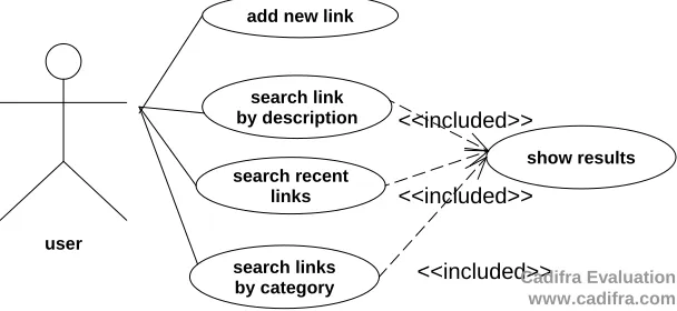
UML use case diagrams used to the description of requirements in the early phase of requirements engineering. The model elements of this kind of diagram are actors, use cases and their according relations. In order to illustrate the presented approach, a simple example is presented in this section. The starting point of the approach is the definition of PIM (functional requirements) as a use case diagram. In Figure 1, a simple use case diagram of a web application to manage an online link catalogue. A user can add a new link or search links in three different ways: by their descriptions, by their categories or see only the most recent links.
user
add new link
search link by description
search recent links
search links by category
show results <<included>>
<<included>>
<<included>> Cadifra Evaluation www.cadifra.com
Each use case must be described using a pattern (template). A pattern is a table with specific fields that must be defined with users. An example of the pattern is shown in table 1. Several fields in the pattern, like precondition, post-condition, etc., are common to other patterns approaches and are widely known and described in other papers and books [5]. A real use case defined by this pattern may be found in table 2.
Table 1. Use case pattern. Name UC-01... Precondition ....
Main sequence 1. The actor….. 2. The system … ....
Alternatives 1.1. If the system … then … and the result is …. 2.1. If the actor … then … and the result is ….
3.1. At any time, the [system/actor] may …. then …. and the result is …
Results 1. System …
.... Postcondition ...
Next paragraphs describe special fields and particular characteristics of the extension. The ideas exposed in next paragraphs may be easily adapted to other requirement techniques and models.
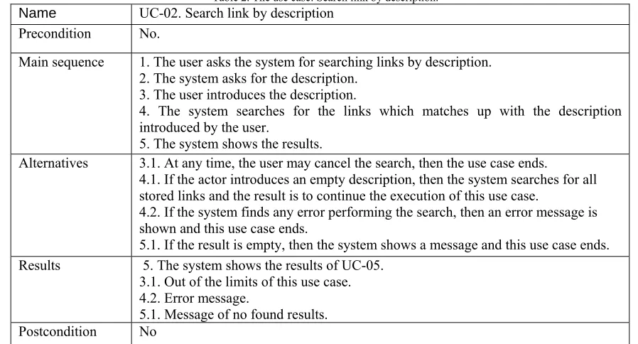
Table 2. The use case: Search link by description. Name UC-02. Search link by description
Precondition No.
Main sequence 1. The user asks the system for searching links by description. 2. The system asks for the description.
3. The user introduces the description.
4. The system searches for the links which matches up with the description introduced by the user.
5. The system shows the results.
Alternatives 3.1. At any time, the user may cancel the search, then the use case ends.
4.1. If the actor introduces an empty description, then the system searches for all stored links and the result is to continue the execution of this use case.
4.2. If the system finds any error performing the search, then an error message is shown and this use case ends.
5.1. If the result is empty, then the system shows a message and this use case ends. Results 5. The system shows the results of UC-05.
3.1. Out of the limits of this use case. 4.2. Error message.
5.1. Message of no found results. Postcondition No
Name: Te name describes the goal of the use case. Every use case has a unique identifier that starts with “UC” letters following one number.
Alternatives: These steps describe the behavior of the system when an error is found or some alternative flow may be executed. An alternative step has got the same elements as the main sequence and some additional elements. The identification of alternatives or errors of the same step. Every step in an alternative section must have an evaluated condition to decide if the alternative step might be executed, and also to decide the executed action when the condition is true, and the result.
Each path in this pattern is offering a suitable test way when the system will be developed. However, no all paths can be defined as a test case because it is impossible to cover the complete number of tests. With the textual notation presented in Table 2, thus we can convert this textual notation into actions in the activity graph to get any possible execution paths are easier to be analyzed. After generating the activity graph, a set of paths are discovered. Each path is a test scenario and then derived the test cases.
A use case describes a set of scenarios [4] that represent concrete executions of the corresponding work unit. A scenario corresponds to a path through the activity graph of the use case which starts at the start vertex, is guided by action post-conditions and edge guards, and ends up in a final vertex. The new in our work we are try to generate all test cases from activity graph that represent all test scenarios from use cases.
We represent the steps of use case as actions and exploit activity graphs to model the behavior of use cases. We start characterizing an action that form the basic components of activity graphs by a name or number that is unique among all actions of the entire use case.
An activity graph (AG) is a directed graph where each node in the activity graph represents a construct (start node, final node, decision node, guard condition, action node), and each edge of the activity graph represents the flow in the use case. Note that an activity graph encapsulates constructs of a use case model in a systematic way suitable for further automation. An activity graph is characterized by a non-empty set S of vertices (i.e. actions), a set of directed edges e S S (transitions). Each edge e = (s, s') is annotated by a guard c(e); the control flow follows an edge e only if guard c(e) holds after the execution of action s, a start vertex s0 S from which paths to all other vertices of the activity graph exist, a non-empty set of final vertices F S.
We propose a set of rules for mapping constructs of a use case into nodes of an activity graph, which are shown in Table 3. We may note that there are five different types of nodes in activity graph: S (start node), E (flow final/action final), A (action), D (decision), C (condition).
Table 3. Mapping rules.
Constructs of use case model Node of Activity Graph
1 start Node Node of type S with no incoming edge
2 Action Final/ Flow Final Node Node of type E with no outgoing edge
3 Decision Node Node of type D
4 Guard Condition associated decision
node Node of type parent node is of type C and associated with condition string. Its D
5 Action Node Node of type A. Its associated string is activity name
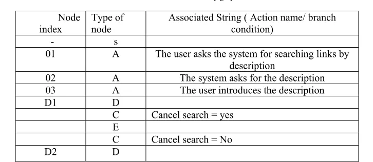
Table 4. NDT for activity graph.
Node index
Type of node
Associated String ( Action name/ branch condition)
- s
01 A The user asks the system for searching links by description
02 A The system asks for the description 03 A The user introduces the description D1 D
C Cancel search = yes E
C Empty description = no
04 A the system searches for the links C Empty description = yes
04.1 A the system searches for all the links D3 D
C No error and result
05 A system shows the links
E
C No error and No result 05.1 A system shows a message E
C Error
04.2 A system shows an error message
3.1 Example
Applying the mapping rules as specified in Table 3 on the running example of use case model we obtain a set of nodes of the activity graph as shown in Figure 2.
To form edges, we consider one-to-one mapping from an edge of the use case model into an edge between two nodes in the activity graph (see Fig. 2). We label the nodes of the activity graph as shown in Fig. 2 and store detail information of each node in the activity graph in a data structure, called Node Description Table (NDT) (see Table 4).
yy
ative2&2)
Figure 2- Activity graph obtained from use case
Yes
No
No yes
No result error
Ok
S
02
D1 03
D2
04.1
D3
05 04.2
05.1
01
04
4. Generating Test Cases from an Activity Graph
In this sub section, we first present fault model, then discuss the existing test coverage criteria and our proposed test coverage criterion. Subsequently, we present our approach of generating test cases from an activity graph following the proposed test coverage criterion.
4.1 Fault model
Every test strategy targets to detect certain categories of faults called its fault model [2]. Our test case generation scheme is based on the following fault model.
Fault in decision: This fault occurs in a decision of a use case model, i.e. a fault in the decision which decides validity or invalidly of condition of actions.
Fault in loop: This fault occurs in either loop entry condition or loop terminating condition or increment operation or decrement operation.
4.2 Test coverage criteria (action path coverage criterion)
Test coverage criteria [16] are a set of rules that guide to decide appropriate elements to be covered to make test case design adequate. We discuss the existing test case coverage criteria followed by our proposed criterion, which we consider as an improved test coverage criterion. We propose a test coverage criterion, called action path coverage criterion. We aim to use this coverage criterion for both branch condition and loop testing but in this paper we used to only branch condition.
Before describing the new coverage criterion, we mention about sequential actions paths, that action path is a sequence of sequential actions from the start action to an end action in an activity graph, where each action (activity) in the sequence has at most one occurrence except those activities that exist within a loop. Each activity in a loop may have at most two occurrences in the sequence.
Now, we define the action path coverage criterion as the following:
Given a set of action paths PA for an activity graph and a set of test cases T, for each action path pi
PA there must be a test case t
T such that when system is executed with a test case t, pi is exercised.We now discuss and use sequential action path to cover faults in branch condition and also, to detect a fault in a decision.
4.3 Generating test cases
We generate test cases following the activity path coverage criterion. To do this, we obtain all action paths from the node of type S to a node of type E in the activity graph. We propose an algorithm Generate Action Paths to generate all action paths. In this algorithm, we use the path enumeration algorithms depth first search traversals of graph. We traverse the activity graph by depth first search.
Algorithm: Generate Action Paths
Input: An activity graph (AG) Output: Set of action paths
1. Initialize: Flag =0; Visits of every node=0; Stack S. 2. Begin
3. Traverse the activity graph using depth first search (DFS). For each node visited during the traversal, count its no of visits and push the node into the stack S;
4. if Visits of the current node = 2 then 5. Set Flag =1;
6. End
7. if Flag=1 and visits of current node = 3 then
8. Backtrack to the node (of type 'D') which has at least a child node with its visits less than two, and then repeatedly pop from S until top of S is the node where recent backtrack has stopped;
9. End
10. if Type of currently visited node='E' then
repeatedly pop from S until top of S is the node where recent backtrack has stopped; visit its child node whose visit count = 0; If S is found to empty, stop else go to step 3 ;
12. End 13. End
Applying the algorithm Generate Action Paths on the activity graph as shown in Fig. 2, we obtain seven action paths as given below in table 5.
Table 5. Derived action paths.
Number path
Derived action paths
1 01 → 02 → 03 → D1(No) → D2(No) → 04 → D3(No error & Results) →05 2 01 → 02 → 03 → D1(No) → D2(No) → 04 → D3(No error & No Results) → 05.1 3 01 →02 → 03 → D1(No) → D2(No) → 04 → D3(Error) → 04.2
4 01 → 02 → 03 →D1(No) → D2(Yes) → 04.1 → D3(No error & Results) → 05 5 01 → 02 →03 → D1(No) → D2(Yes) → 04.1 → D3(No error & No Results) → 05.1 6 01 → 02 → 03 → D1(No) → D2(Yes) → 04.1 → D3(Error) → 04.2
7 01 → 02 → 03 → D1(Yes)
For the running example, we have total seven action paths, which we process for generating test cases. Test case in our approach consists of two components - sequence of branch conditions, action sequence. Action sequence constitutes the expected system behavior. On the other hand, we consider the sequence of branch conditions as a source of test input. Each branch condition in sequence of branch conditions corresponds to the some input data specified in the textual description of the use case whose use case model is being considered. With the help of system analyst, we may find these input values corresponding to each branch condition.
As a part of test case generation, we obtain necessary values of all two components of a test case from the corresponding action path itself. For this, we use node description table (NDT) constructed for the activity graph. Constituent parts of test case Ti are filled up after processing of corresponding activity path PAi with help of following steps.
If type of the current node of PAi is either 'S' or 'E' or 'D', it is ignored.
If type of the current node of PAi is 'C', branch condition associated that node is the next branch condition in 'sequence of branch conditions' part of Ti.
If type of the current node of PAi is 'A', action name associated with that node is the next action in 'action sequence' part of Ti.
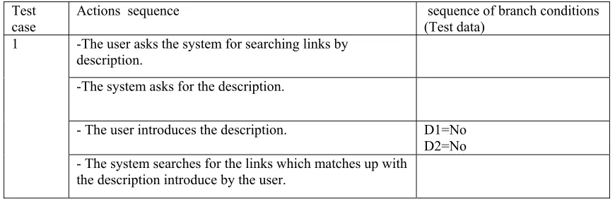
Table 6 lists test cases which are obtained from all action paths. Here, test cases cover fault in decision. Table 6. lists test cases.
Test
case Actions sequence sequence of branch conditions (Test data) 1 -The user asks the system for searching links by
description.
-The system asks for the description.
- The user introduces the description. D1=No D2=No - The system searches for the links which matches up with
-system shows the results D3=No error and Results
2 -The user asks the system for searching links by description.
-The system asks for the description.
- The user introduces the description. D1=No D2=No - The system searches for the links which matches up with
the description introduce by the user.
-system shows a message. D3=No error and No Results
3 -The user asks the system for searching links by description.
-The system asks for the description.
- The user introduces the description. D1=No D2=No - The system searches for the links which matches up with
the description introduce by the user.
-system shows an error message. D3= Error
4 -The user asks the system for searching links by description.
-The system asks for the description.
- The user introduces the description. D1=No D2=Yes - The system searches for all the links
-system shows the results D3= No error and Results
5
-The user asks the system for searching links by description.
-The system asks for the description.
- The user introduces the description. D1=No D2=Yes - The system searches for all the links.
-system shows the results D3= No error and No Results
6 -The user asks the system for searching links by description.
-The system asks for the description.
- The user introduces the description. D1=No D2=Yes - The system searches for all the links.
-system shows the results D3= Error
7 -The user asks the system for searching links by description.
-The system asks for the description.
- The user introduces the description. D1=Yes
5. Test Adequacy Criteria
Test adequacy criterion specifies the requirement of a particular testing. In software testing, the definition of test adequacy is given in [16] as a measurement function. But in our case, the UML use case model is different because it is in the form of model instead of code. We will define especially the action path coverage of activity graph. The definition of coverage of UML use case model by using activity graph is as follows:
From the above example: 1. First scenario
The user asks the system for searching links by description The system asks for the description
Valid the user introduces the description Valid the system searches for the links The system shows the results End.
The value of action path coverage =
AG
in the
paths
action
all
AG
in
paths
action
traversed
The value of action path coverage =1/7=14%.
2. second scenario
The user asks the system for searching links by description The system asks for the description
Valid the user introduces the description Valid the system searches for the links The system shows a message End.
The value of action path coverage =1/7=14%. 3. third scenario
The user asks the system for searching links by description The system asks for the description
Valid the user introduces the description Valid the system searches for the links The system shows an error message End.
The value of action path coverage =1/7=14%. 4. fourth scenario
The user asks the system for searching links by description The system asks for the description
Valid the user introduces the description Valid the system searches for all the links The system shows the results End.
The value of action path coverage =1/7=14%. 5. fifth scenario
The user asks the system for searching links by description The system asks for the description
Valid the user introduces the description Valid the system searches for all the links The system shows a message End.
The value of action path coverage =1/7=14%. 6. sixth scenario
The user asks the system for searching links by description The system asks for the description
Valid the user introduces the description Valid the system searches for all the links The system shows an error message End.
The value of action path coverage =1/7=14%. 7. seventh scenario
The user asks the system for searching links by description The system asks for the description
Invalid the user introduces the description End.
The value of action path coverage =1/7=14%.
We can conclude from analysis execution of our algorithm that the value of action path coverage was 100% of the activity graph.
6. Conclusion
In this paper, we can represent the UML use case behavior model as one of models that describes a platform independent model and we can use an approach to generate test cases from use cases behavior model by converting use case model into an activity graph and these test cases are derived from functional requirement.
References
[1] Basanieri, F.; Bertolino, A.; Marchetti, E., (2002). A UML-based approach to system testing, in: J.-M. Jezequel, H. Hussmann and S. Cook, editors, UML, LNCS 2460.
[2] Binder, R. V., (1999). Testing Object-Oriented Systems Models, Patterns, and Tools. Addison Wesley, Reading, Massachusetts.
[3] Briand, L.C.; Labiche ,Y., (2002). A UML-Based Approach to System Testing, Journal of Software and Systems Modelling, Vol. 1 No.1 pp. 10-42.
[4] J. M. Carroll (Ed.), (1995). Scenario-Based Design — Envisioning Work and Technology in System Development. John Wiley & Sons, Inc., New York.
[5] Cockburn, A., (2000). Writing Effective Use Cases. Addison-Wesley 1st edition. USA.
[6] Frankel, D., (2003). Model Driven Architecture Applying MDA to Enterprise Computing”, Wiley. [7] Gregory, E.T., (2002). A Systems Approach to Automated Object-Oriented Integration Testing”, Ph.D. Dissertation, Boston University.
[8] Heckel, R.; Lohmann, M., (2003). Towards Model Driven Testing”, In TACoS International Workshop on Test and Analysis of Component Based Systems, in conjunction with ETAPS, pp. 284–29. [9] Hassan, A. H.; Yousif, Z.E, (2010). Test Cases Generation Using a Mathematical Representation for the Dynamic Behavior of PIM. Journal of Mathematics and Technology, April 26.
[10] Navarro, P.L.; Ruiz, D. S.; Perez, G.M., (2010). A Proposal for Automatic Testing of GUIs Based on Annotated Use Cases. Advances in Software Engineering. Vol.2010, Article ID 671284, doi 10.1155/2010/671284,
[11] Nebut, C.; Fleury, F. L.; Traon, Y.; Jézéquel, J. M., (2006). Automatic Test Generation: A Use Case Driven Approach. IEEE Transactions on Software Engineering Vol. 32. 3. March.
[12] Ostrand, T.J.; Balcer, M.J., (1988). The Category-Partition Method. Communications of the ACM. 676- 686
[13] Raistrick, C.; Francis, P.; Wright, J.; Carter, C.; Wilkie, I., (2004). Model Driven Architecture with Executable UML, Cambridge University Press.
[14] Rational Software Corporation, Rational Unified Process, Version 2001A.04.00, Copyright © 1987 - 2001.
[15] Soley, R., O. S. S. Group, (2000). Model driven architecture, ftp://ftp.omg.org/pub/docs/omg/00-11- 05.pdf.