High-Efficiency Modular High Step-Up Interleaved
Dc-Dc Boost Converter Using Fuzzy Controller
B.Rajasekaran, M.L.Bharathi
Abstract: This paper deals with the simulation of closed loop and open loop controlled Interleaved Boost Converter (ILBC). It is seen that, for higher power applications, more modules can be paralleled to increase the power rating and the dynamic performance. One of the challenge in designing a boost converter for high power application is how to handle the high current at the input side. In this paper an interleaved boost dc-dc converter is proposed for current sharing on high power application. Moreover, this converter also reduces the ripple current. The simulated results are presented with R load.
Keywords: Boost converter, Closed loop control, Open loop control, Interleaved, Ripple reductions, Fuzzy controller, Hysteresis controller
————————————————————
1
I
NTRODUCTIONPower converters have required improvement in the power efficiency as well as reduction of size and weight especially in mobile information/communication devices, traction converters, power control units for electric/hybrid vehicle, etc. Passive components and cooling devices usually occupy a much larger space than semiconductor devices in power electronics building block. It is well known that when many DGs are connected to utility grids, they can cause problems such as voltage rise and protection problem in the utility grid. To solve these problems, new concepts of electric power systems are proposed [1]. Resonant converters eliminate most of the switching losses encountered in Pulse Width Modulation converters. The ac-tive device is switched with either Zero Current Switching or Zero Voltage Switching at its terminals. When current through the switch is made zero, it is turned on /off, it is known as zero current switching and when voltage across the switch is made zero, it is turned on / off, it is known as zero voltage switching [2]. The main objective of this paper is to develop a modular high-efficiency high step-up boost converter with a forward energy-delivering circuit integrated voltage-doubler as an interface for high power applications. In the proposed topology, the inherent energy self-resetting capability of auxiliary transformer can be achieved without any resetting winding. Moreover, advantages of the proposed converter module such as low switcher voltage stress, lower duty ratio, and higher voltage transfer ratio features are obtained [3].
The DC-DC Converter has low switching power losses and high power efficiency. The use of single transformers gives a low-profile design for the step-up DC-DC converter for low-DC renewable energy sources like photovoltaic module and fuel cell [4]. The ILBC converter is gaining its popularity. An Interleaved boost converter usually combines more than two conventional topologies, and the current in the element of the interleaved boost converter is half of the conventional topology in the same power condition. Besides, the input current ripple and output voltage ripple of the interleaved boost converter are lower than those of the conventional topologies. Interleaved boost converters has higher efficiency than the conventional single boost converter [5]. In the interleaved boost converter topology, one important operating parameter is called the duty cycle D. For the boost converter, the ideal duty cycle is the ratio of voltage output and input difference with output voltage[8]. As already well known, the input current and output voltage ripple of interleaved boost dc-dc converter can be minimized by virtue of interleaving operation. Moreover, the converter input current can be shared among the phases, which is desirable for heat dissipation[6]. Therefore, the converter reliability and efficiency can be improved significantly. In this paper, comprehensive simulation analyses are presented to illustrate the performance of the interleaved boost dc-dc converter. The features of the interleaved boost dc-dc converter, the principle of operation and the design procedure are discussed in this paper. The simulation and experimental results are presented and compared. The voltage stresses of the main switch and the auxiliary switches are equal and the duty cycle of the proposed topology can be increased to more than 50%. The proposed converter is the parallel of the boost converters and their gate signals are generated by fuzzy controller and this makes the operation more accurate. Moreover, by establishing the fuzzy controller for the interleaved converter can further reduce the size and cost[7]. This work proposes simulation and model for closed loop control system.
2
ILBC
OPERATING
PRINCIPLE
The proposed interleaved converter topology with high voltage transfer ratio is proposed as shown in Fig. 1. It can be seen from Fig. 1, the proposed converter consists of two-phase circuits with interleaved operation. The first phase is a boost integrating the forward-type circuit structure, which includes inductor L1 and switch S1 for the ____________________________
B.Rajasekaran is pursuing his post graduation in
power electronics and industrial drives(2012-2014) in Sathyabama University,
Email ID- [email protected],
Bharathi.M.L, She is currently a research scholar in Sathyabama University.
268 boost and an isolated forward energy-delivering circuit with
turn ratio N. The second phase of the proposed converter is a boost circuit which contains inductor L2, switch S2, blocking capacitor C2, and diode D2 followed by the common output capacitor Co. From Fig. 1, one can see that the proposed converter is basically based on the conventional voltage-doubler for the second phase circuit. However, for the first phase, in order to reduce the voltage stress of switch S1 and diode D1, an additional blocking capacitor C1, is added to function as that of C2 for the second phase.
Fig.1 Proposed modular Interleaved high step-up boost converter topology.
3
MODES
OF
OPERATION
Mode 1:
Switches S1, S2 are turned on,
Diode Df1 is forward biased
Diodes D1,D2,Df2 are reverse biased
Both iL1 and iL2 are increasing to store energy in L1 and L2
The input power is delivered to the secondary side through the isolation transformer and inductor Lf to charge capacitor C1.Mode 2:
switch S1 remains conducting
S2 is turned off.
D2 is forward biased.
The energy stored in inductor L2 is now released through C2 and D2 to the inverter through C3.
However, the first phase circuit including the forward-type converter remains the same.
Modes 3:
For this operation mode, both S1 and S2 are turned on.
The corresponding operating principle turns out to be the same as Mode 1.
Mode 4:
S1 is turned off, and S2 is turned on.
Diode D2 and Df1 are reverse biased
Diode D1 is forward biased.
Since diode Df1 is reverse biased, diode Df2 must turn on to conduct the inductor current iLf.
The energy stored in L1 is now released through C1 and D1 to charge capacitor C0 for compensating the lost charges in previous modes.
The energy stored in transformer is now treated to perform the self-resetting operation without additional resetting winding.
4
SIMULATION RESULTS AND OPERATION
OF FUZZY CONTROLLER
Digital simulation is done by using the elements of MATLAB Simulink and the results are presented here.
A. Open loop control system with R-Load
The Simulink diagram of interleaved boost converter with R-Load is shown in Fig 2. The voltage and current measurement blocks are connected to measure the output voltage and output current. The scopes are connected to measure the driving pulse and voltage across the switch. DC input voltage 24v DC is shown in the Fig.3. The gating pulse across the switch is shown in Fig.4.The output current 16Amps and output voltage 160V DC is shown in the Fig.5 & Fig.6
Fig.2 Circuit Diagram of ILBC with R-load
t
Fig.3 Input Voltage
t Fig.4 Switching Pulse V
O L T S
VGS1
t Fig.5 Output Current
t Fig.6 Output Voltage
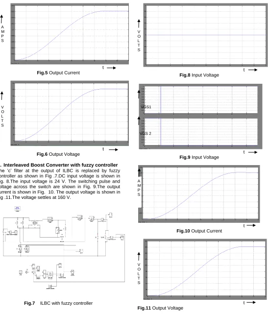
B. Interleaved Boost Converter with fuzzy controller The ‗c‘ filter at the output of ILBC is replaced by fuzzy controller as shown in Fig .7.DC input voltage is shown in Fig. 8.The input voltage is 24 V. The switching pulse and voltage across the switch are shown in Fig. 9.The output current is shown in Fig. 10. The output voltage is shown in Fig .11.The voltage settles at 160 V.
Fig.7 ILBC with fuzzy controller
t Fig.8 Input Voltage
t Fig.9 Input Voltage
t Fig.10 Output Current
t Fig.11 Output Voltage
C. Fuzzy Controller and its Rules
BASIC CONCEPT OF FUZZY LOGIC:
Zadeh – ―Attempt to implement human control logic‖
V O L T S A M P S
V O L T S
VGS1
VGS 2
A M P S
270
Do away with crisp sets, Boolean, true/false, etc.
Allow for fractions, partial data, imprecise data.
Designed to control something.
They can be in software or hardware.
can be used in anything from small circuits to large mainframes.
CONSTRUCTING A FUZZY CONTROLLER:
Create the membership values (fuzzify).
Specify the rule table.
Determine your procedure for defuzzifying the result.
RULE TABLE:
Specify the Rule Table as in Fig. 12.
The rule table must now be created to determine which output ranges are used.
The table is an intersection of the two inputs.
Fig.12. Fuzzy Rule Table
LIST OF RULES:
If angle is Z and angular velocity is Z then speed is Z
If angle is Z and angular velocity is NH then speed is
NH
If angle is Z and angular velocity is NL then speed is
NL
If angle is Z and angular velocity is PL then speed is
PL
If angle is Z and angular velocity is PH then speed is
PH
If angle is NH and angular velocity is Z then speed is
NH
If angle is NL and angular velocity is Z then speed is
NL
If angle is PL and angular velocity is Z then speed is
PL
If angle is PH and angular velocity is Z then speed is
PH
If angle is NL and angular velocity is PL then speed is
Z
If angle is PL and angular velocity is NL then speed is
Z
D. Derivative Block in fuzzy controller
In Fig 13 the functional derivative block used in fuzzy controller is shown, using hysteresis controller the output is obtained. Fig.14 shows the step input signal in the fuzzy controller. The
output voltage is taken as the negative voltage that is given to the functional block, and a carrier wave signal generator is used for reference to the input signal shown in fig.15, and comparing both the step input and the reference carrier signal the switching pulses are generated shown in the fig.9.
Fig.13 Derivative block used in fuzzy controller
t Fig.14 Step Input Signal
t
Fig.15 Reference Carrier Signal
5
CONCLUSION
High-efficiency modular high step-up ILBC closed loop controlled is simulated with R load. The simulation results are in line with predictions. The scope of this work is designing, modeling and simulation of closed loop controlled ILBC. The hardware is yet to be implemented. The closed loop model is developed using the blocks of Simulink. Closed loop system is capable of reducing steady state error.
6
ACKNOWLEDGMENT
This work was supported in part by the management of Sathyabama University, India, chennai 600019, and the Faculties of EEE Department, Sathyabama University. The Authors wish to thank the Researchers A
M P L I T U D E
Dr.V.Sivachidambaranathan, Mr.V.SenthilNayagam for contributing useful information.
7
REFERENCES
[1] Sivachidambaranathan.V & S.S.Dash (2010), ―Simulation of Half Bridge Series Resonant PFC DC to DC Converter‖, IEEE International Conference on ―Recent Advances in Space Technology Services & Climate Change – 2010‖ (RSTS&CC-2010), Sathyabama University in association with Indian Space Research Organisation (ISRO), Bangalore and IEEE, ISBN 978-1-4244-9184-1, November 13-15, IEEE Explore pp 146-148. (INSPEC Accession Number : 11824032)
[2] Sivachidambaranathan.V (2013) ―Series Parallel Resonant Converter for Low Power Applications‖, Indian Journal of Applied Research (ISSN: 2249-555X), Vol 3, Issue 12, Dec 2013, pp 188-189.
[3] Ching-Ming Lai, High-Efficiency Modular High Step-Up Interleaved Boost Converter for DC-Microgrid Applications, Member, IEEE, Ching-Tsai Pan, Member, IEEE, and Ming-Chieh Cheng, Student Member, IEEE.
[4] SenthilNayagam.V and Sivakumar.J, Implementation of Dual Active-Clamped Step-Up DC-DC Converter with Reduced Voltage Stress For Low-DC Renewable Energy Sources, CiiT International Journal of Programmable Device Circuits and Systems ISSN 0974 – 973X & Online: ISSN 0974 – 9624, 2013.
[5] Burak Akın YTU electrical engineering department C-216 davutpasa İstanbul TURKEY [email protected] Comparison of Conventional and Interleaved PFC Boost Converters for Fast and Efficient Charge of Li-ion Batteries Used in Electrical Cars. 2012 International Conference on Power and Energy Systems Lecture Notes in Information Technology, Vol.13, 2012
[6] Y.-C. Hsieh, T.-C. Hsueh, and H.-C. Yen, ―An interleaved boost converter with zero-voltage transition,‖ IEEE Trans. Power Electron., vol. 24, no. 4, pp. 973–978, Apr. 2009.
[7] Gaurav, Amrit Kaur, Comparison between Conventional PID and Fuzzy Logic Controller for Liquid Flow Control: Performance Evaluation of Fuzzy Logic and PID Controller by Using MATLAB/Simulink, International Journal of Innovative Technology and Exploring Engineering (IJITEE) ISSN: 2278-3075, Volume-1, Issue-1, June 2012
[8] S.Daison Stallon*, K.Vinoth Kumar*, S.Suresh Kumar** * School of Electrical Sciences, Karunya University, Coimbatore - 641114, Tamil Nadu, India ** Research Director & Professor, Department of ECE, Dr.NGP Institute of Technology, Coimbatore - 641048, Tamilnadu, India, High Efficient Module of
Boost Converter in PV Module, International Journal of Electrical and Computer Engineering (IJECE) Vol.2, No.6, December 2012, pp. 758~781 ISSN: 2088-8708.
[9] Majid Pahlevaninezhad, Member, IEEE, Pritam Das, Member, IEEE, Josef Drobnik, Senior Member, IEEE, Praveen K. Jain, Fellow, IEEE, and Alireza Bakhshai, Senior Member, IEEE, A ZVS Interleaved Boost AC/DC Converter Used in Plug-in Electric Vehicles,
IEEE TRANSACTIONS ON POWER
ELECTRONICS, VOL. 27, NO. 8, AUGUST 2012.