e-ISSN: 2278-067X, p-ISSN: 2278-800X, www.ijerd.com
Volume 11, Issue 02 (February 2015), PP.24-28
Digitally Programmable Grounded Impedance Multiplier
N. Afzal
Department of Electronics and Communication Engineering, Jamia Millia Islamia, New Delhi-110025, India.
Abstract:- A novel digitally programmable generalized impedance multiplier is presented. It uses second
generation current conveyor and a digital control module. The new multiplier can provide digital control to grounded impedance functions such as, resistor, capacitor, inductor without quantizing the signal. The technique used is simple, versatile as well as compatible for microminiaturization in contemporary IC technologies. The simulation results on digitally programmable generalized impedance multiplier verify the theory.
Keywords:- Current conveyor, multiplier.
I.
INTRODUCTION
In recent years the second generation current conveyors (CCIIs) have proved to be functionally flexible and versatile building block. It possess higher signal bandwidth, greater linearity and large dynamic range [1-2]. As a result it is gaining wide acceptance as a building block for designing voltage/current mode analog signal processing circuits [3-6]. In the mixed signal systems the on chip control of the systems’ parameter can be provided through digital means with high resolution capability and the reconfigurability[4-7]. However, not much content is available in the technical literature on the subject.
In this paper a novel digitally programmable grounded multiplier (DPGIM) using second generation current conveyor is presented. To demonstrate the versatility of the DPGIM, digitally controlled grounded resistor(R), capacitor(C) and inductor are realized. The circuit consists of a CCII, a digital control module (DCM), which is realized using R-2R ladder and a n-bit switching array, along with impedance under control. The realized DPGIM is simulated for positive and negative resistors using PSPICE.
II.
DIGITAL CONTROL MODULE
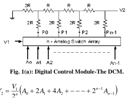
The realization of the digital control module (DCM) used in the DPGIM is shown in Figure 1(a), which uses R-2R ladder and analog switching array [6]. Its routine analysis yields the output voltage V2 as
Fig. 1(a): Digital Control Module-The DCM.
1
1 2
1 0 1
2
2
4
2
2
n nn
A
A
A
A
V
V
(1)where, A0, A1, …, An-1 are the bit values of the n-bit digital control word (N). Equation (1) can also be expressed as
1 1 2 KV
V (2)
where, K1 = N/2n .
K1
V1
N
V2
Fig 1(b): The K1 – Block.
The transfer gain can be expressed as
2 1
2
K
V
V
(3)
where, K2 = K1 K1 = (N/2n)2. Henceforththis double stageblock shall be referred as the K2 – Block. Its equivalent is also shown in Figure1(c). It is obvious from equation (2) and (3) that the transfer gain of the K1 and K2 modules can be controlled through digital control word (N).
Fig. 1(c): The K2 – Block
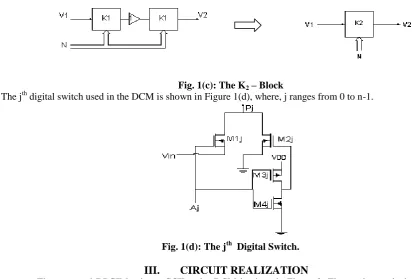
The jth digital switch used in the DCM is shown in Figure 1(d), where, j ranges from 0 to n-1.
Fig. 1(d): The jth Digital Switch.
III.
CIRCUIT REALIZATION
The proposed DPGIM using a CCII and a DCM is given in Figure 2. The routine analysis yields its impedance function as
KZ
I
V
Z
in
(4a)where, K (= N/2n )is the transfer gain of the DCM and N is an n-bit control word. Thus, the realized impedance of equation (4) reduces to
Z N Zin n
2 (4b)
It is to be noted that for negative CCII the realized impedance Zin is positive while for positive CCII, anegative Zin is realized. From equation (4b) it is clear that the impedance seen at the input port of the Figure 2 can easily be controlled by digital word N, in turn the terminating impedance Z is controlled. The terminating impedance Z may be selected either resistor(R), capacitor (C) or inductor (L) or any combination of these components. Thus the circuit realizes digitally controlled positive as well as negative impedance multiplier
Case 1: Digitally Programmable
RIn Figure 2, if Z is considered as resistor i.e., Z = R, equation (4) reduces to
Zin = Re (5a)
For K = K1
R
N
R
e n2
(5b)and for K = K2
R
N
R
e n2
2
(5c)It is can be seen from equation (5) that the realized effective resistance Re is programmable through digital control word N. For, K=K1, Re is directly related to the digital control word N, while for K=K2, It is directly related to N2.
Case 2: Digitally Programmable
CIf Z in Figure 2 is assumed as capacitor i.e. Z = 1/sC, equation (4) reduces to
e in
sC
Z
1
(6a)For K = K1
C N C n e 2 (6b)
while for K = K2
C N C n e 2 2 (6c)
Thus it is obvious from equation (6) that through digital control word (N), the realized effective capacitance(Ce) can be controlled inversely through N or N2.
Case 3: Digitally Programmable
LIn Figure 2 if Z is considered as an inductor i.e. Z = sL, equation (4) reduces to
Zin = s Le (7a)
Again for K = K1
L N Le n
2 (7b)
L N
Le n
2
2
(7c)
Thus by controlling the digital control word N the realized effective inductance Le is also programmable either through N or N2.
IV.
SIMULATION RESULTS
The practical validity of the proposed digitally programmable grounded impedance multiplier is simulated using PSPICE for
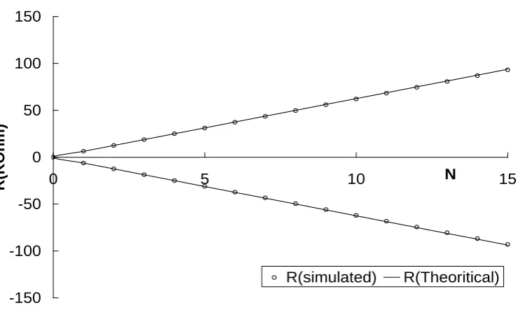
R. The SPICE model of CCII available in the technical literature was used [2]. The digital control module of Figure (1) was implemented for 4-bit with W/L ratio of unity. The voltage - current plot obtained from PSPICE simulation for the DGPIM of Figure 2 with R=100KOhm for various N is shown in Figure 3(a).Fig. 3(a): V-I plot for digitally programmable positive and negative resistors for \ different digital control word N realized from the DPIM.
Fig. 3(b): Variation of R with N for positive and negative resistor. -8
-4 0 4 8
-100 -60 -20 20 60 100
I (m
A
)
V (mV)
N=2
N=3 N=3
N=15 N=15
N=6 N=2
N=6
-150
-100
-50
0
50
100
150
0
5
10
N
15
R(
KOhm
)
Also, by varying the digital control word (N) the resistance
R is controlled and the results obtained are shown in Figure 3b. The Figure 3 clearly exhibits the responses in close conformity with the design.V.
CONCLUSION
A digitally programmable impedance multiplier using CCII is presented. This impedance multiplier realizesdigitally controlled positive as well as negative grounded resistor, capacitor, and inductor. The technique used is simple versatile as well as compatible in contemporary IC technologies. It is to be noted that the digitally programmable circuit parameters in all the realizations are reconfigurable. The resolution of the digital control can be improved by using larger number of bits in the digital control module. The realized circuit was designed and simulated for
R using PSPICE. The results thus obtained verify the theory.REFERENCES
[1]. B. Wilson, (1992). Tutorial review: Trends in current conveyors and current mode amplifier design. Int. J. Electronics, 73(3), 573-583.
[2]. J. A. Svobodo, (1994). Transfer function syntheses using current conveyors. International Journal of Electronics, 76, 611-614.
[3]. I. A. Khan and Maheshwari, (2000). Simple first order all pass section single CCII. International Journal of Electronics, Vol. 87, No. 3, pp. 303 - 306.
[4]. H. Alzaher, (2006). CMOS digitally programmable inductance, ICM – 06, Saudi Arabia.
[5]. S. M. Al-Shahrani, and M. Al-Gahtani, (2006). A new poly-phase current-mode filter using digitally programmable current-controlled current-conveyor, ICM - 06, Saudi Arabia.
[6]. I. A. Khan, M. R. Khan and N. Afzal, (2006). Digitally programmable multifunctional current mode filter using CCIIs. Journal of Active and Passive Devices. Vol. 1, pp. 213-220.