Abstract—In this study, in order to investigate wave-induced
motion of offshore support structures simulating marine installation by crane lifting and seabed down positioning, wave-induced motion tests were carried out for the three types of offshore support structures under the irregular wave conditions. As the results of this study, it was found that the main factors influenced on the wave-induced swing motion of offshore support structures were the center of gravity and period of free decay motion. Wave-induced motions of GBS and Hybrid were lower than the Monopile since the centers of gravity were lower than the Monopile. GBS model indicated lower wave-induced motion than the Hybrid at the long period of wave condition, since the period of free decay motion of GBS was relatively longer than the Monopile and Hybrid.
Index Terms—Support structure, wave-induced motion, test,
marine installation, irregular wave.
I. INTRODUCTION
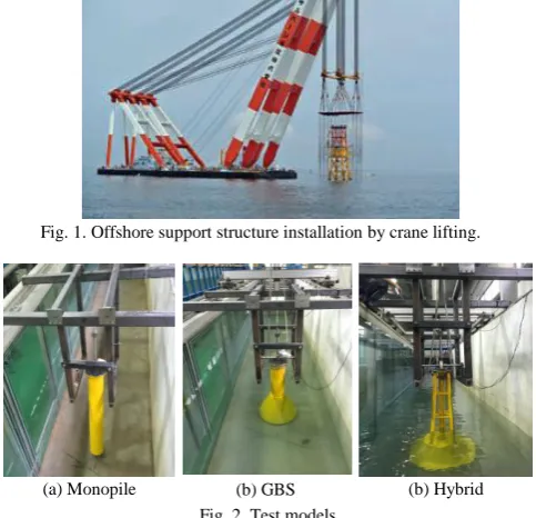
Most of the Offshore support structures have been installed by the crane lifting and seabed down positioning at marine conditions of the wave and current [1], as presented in Fig. 1. In order to exactly down positioning offshore support structure on arranged seabed point and to prevent breakdown of the boom of the offshore crane due to the large motion of the offshore support structures [2], it is important to minimize motion of offshore support structure by the wave and current during the seabed down positioning [3]. Therefore, marine installation works of offshore support structures have been carried out only during the steady-state marine condition of no-wave and no-current.
However, the steady-state marine condition occurs during the short time in the days. Namely, marine installation works has been carried out in short time during the days and it caused increasing of marine working periods and installation cost due to the expansive cost of offshore crane and vessel. If wave-induced motion of offshore support structure during the crane lifting and seabed down positioning can be minimized, marine installation works can be expanded to the certain levels of marine conditions of some-wave and some-current. Accordingly, marine working time can be expanded during the days and installation cost can be reduced dramatically.
Manuscript received November 15, 2016; revised May 15, 2017. This work was supported in part by the South Korea Government, Ministry of Trade, Industry, and Energy, and Ministry of Oceans and Fisheries (sponsor and financial support acknowledgment goes here).
The authors are with the Korea Institute of Civil Engineering and Building Technology, Goyang, Gyeonggi, South Korea (e-mail: [email protected], [email protected]).
Only a few model tests related to marine installation can be found in literature survey [4]. Nam et al. [4] carried out experimental and numerical study on coupled motion response of a floating crane vessel and a lifted subsea manifold in deep water and reported that the motion response of the lifted object were strongly affected by the added-mass and hydrodynamic damping of the lifted object.
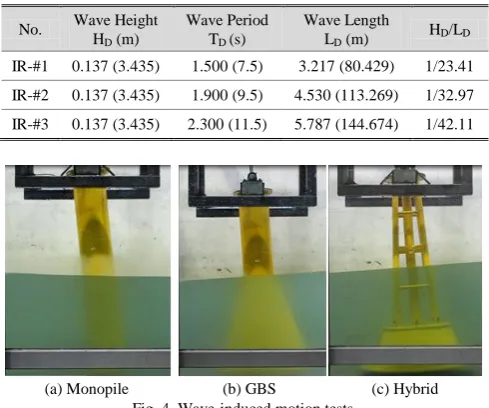
In this study, in order to investigate wave-induced motion of offshore support structures simulating marine installation by crane lifting and seabed down positioning, wave-induced motion tests were carried out for the three types of offshore support structures, Monopile [5], GBS (Gravity Base System) [5], [6], and Hybrid [7]-[9] under the irregular wave conditions. Also, in order to evaluate free decay motions of periods and damping, free decay tests into the seawater were carried out prior to wave-induced motion test. Based on the wave-induced motion resulting from the tests, wave-induced motions to the offshore support structure types were analyzed and compared with each other.
Fig. 1. Offshore support structure installation by crane lifting.
(a) Monopile (b) GBS (b) Hybrid
Fig. 2. Test models.
II. WAVE-INDUCED MOTION TESTS
A. Test Models
In order to investigate wave-induced motion of offshore support structures simulating marine installation by crane lifting and seabed down positioning, three types of offshore support structures of Monopile, GBS, and Hybrid were
Comparison of Wave-Induced Swing Motion of Offshore Structures
under Irregular Wave Simulating Seabed Positioning by Crane
fabricated and tested under the irregular wave conditions, as
presented in Fig. 2.
Three types of support structures were designed and fabricated to have the same total weight and height applying
Froude scale law of 1:25. The details of three offshore support structure models were summarized in Table I.
TABLEI:THE DETAILS OF TEST MODELS
No. Type Dimension (mm) Weight (kg) Wave Area (cm2) Wave Volume (cm3) Scale
1 Mono 240(D1)×240 D2)×1,500(H) 203.00 1,920.0 (1.0) 11,520.0 (1.0) 1:25
2 GBS 260(D1)×740(D2)×1,500(H) 203.00 4,000.0 (2.1) 50,000.0 (4.3) 1:25
3 Hybrid 272(D1)×740(D2)×1,500(H)
*** D1=(4·Ø48+Ø80)*** 203.00 3,462.4 (1.8) 38,863.1 (3.4) 1:25
*** D1: top diameter, D2: bottom diameter, H: height
B. Test Setup
In order to investigate wave-induced motion of the offshore support structures simulating marine installation by crane lifting and seabed down positioning, experimental studies were conducted at the flume of the CheonNam National University of the South Korea in July, 2015. The dimensions of the flume were 100 m (L) × 2.0 m (W) × 3.0 m (H).
Wave force
Swing Swing
Hinge
(a) Wave-induced motion test method
(a) Installation of test models Fig. 3. Test setup.
The mechanical frame was specially designed and fabricated to allow wave-induced swing motion of test models with the minimum friction. It has known that the coupling effects of dynamic tension of the crane rope have nonlinearity and influence on the wave-induced motions of support structure [4], [10], [11]. Therefore, in order to remove
dynamic tension effect of the crane rope during the crane lifting and seabed down positioning, hinge part of the swing motion of the offshore support structures made at the top of the test models, not crane top, and wave-induced motions were measured using the wire-displacement gauge installed at the rebar connected to the top of test model, as presented in Fig. 3.
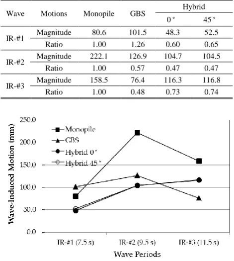
C. Wave Conditions
Offshore support structure models were tested under the three different irregular wave conditions, as presented in Table II and Fig. 4. Marine installation works of offshore support structures have been carried out only during the steady-state marine condition of no-wave and no-current and the purpose of this study was to expand marine installation works to the certain levels of marine conditions of some-wave and some-current. Therefore, wave condition of this study should be low level of wave height and wave period.
TABLEII:IRREGULAR WAVE CONDITIONS
No. Wave Height HD (m)
Wave Period TD (s)
Wave Length
LD (m) HD/LD
IR-#1 0.137 (3.435) 1.500 (7.5) 3.217 (80.429) 1/23.41
IR-#2 0.137 (3.435) 1.900 (9.5) 4.530 (113.269) 1/32.97
IR-#3 0.137 (3.435) 2.300 (11.5) 5.787 (144.674) 1/42.11
(a) Monopile (b) GBS (c) Hybrid
Fig. 4. Wave-induced motion tests.
However, it was difficult to generate low levels of wave height and wave period at the wave maker of the flume because of the limited capacity of the wave maker. Therefore, the wave height (HW)3.435 m, which was corresponded to
normal wave height condition for 1 year, was selected for the full-scale models and it was scale downed to 0.137 m for the small-scale model. The wave variables of this wave-induced motion tests were the wave periods. For the wave height 3.435 m, three cases of wave period (PW) 7.5 s, 9.5 s., and 11.5 s
2.3 s for the small-scale model. Water depth was 20.0 m and scale downed to 0.8 m. In case of Hybrid model, incident wave 45° as well as 0° was added to verify maximum wave-induced motion according to the incident wave effect. Since the upper part of Hybrid model consist of the multiplies and indicated different wave force to the wave direction, in order to act incident wave 45° effects, Hybrid model was repositioned to the 45° direction for the wave direction.
Wave-induced motion tests were carried out during the 300 s. Among the measured time series wire-displacement data set, 50 s data sets from 200 s to 250 s was selected as the typical wave-induced motion, which was well present wave-induced motions of test models.
III. FREE DECAY MOTIONS INTO THE SEAWATER
As the results of free decay motion tests into the seawater, measured free decay motions for the small-scale models were presented in Fig. 5 for the offshore support structure types, respectively. Periods of free decay motions for the test models resulting from tests were summarized in Table III.
(a) Monopile
(b) GBS
(c) Hybrid
Fig. 5. Measured free decay motions.
TABLEIII:PERIODS OF FREE DECAY MOTIONS INTO THE SEAWATER
Monopile GBS Hybrid: 0° Hybrid: 45°
Dry 2.1 s. 2.3 s. 2.4 s. 2.4 s.
Wet 2.7 s. 12.8 s. 3.8 s. 3.8 s.
IV. WAVE-INDUCED MOTIONS
As the results of wave-induced motion tests, measured wave-induced motions for the small-scale models were presented in Fig. 6 to Fig. 9 for the offshore support structure types, respectively. Noise of measured data set was
eliminated using moving average data processing method. Based on the measured data, minimum and maximum magnitudes of the wave-induced motions were calculated. Amplitudes, swing distance from maximum to minimum, of wave-induced motions resulting from tests were summarized in Table IV and Fig. 10.
Test results of this study indicated a different tendency for the offshore support structure types. In cases of the Hybrid, as the wave period increased from wave IR-#1 (7.5 s) to wave IR-#3 (11.5 s), wave-induced motions of support structure increased [4], as presented in Fig. 8, 9, and 10. Wave-induced motions for the Hybrid models at the short wave period of 7.5 s were about 41.5 % and 44.5 % level, respectively, of the long wave period of 11.5 s. However, in cases of Monopile and GBS, wave-induced motions of support structure were maximized at the wave period 9.5 s (wave IR-#2), as presented in Fig. 10.
(a) Wave IR-#1
(b) Wave IR-#2
(c) Wave IR-#3
Fig. 6. Measured wave-induced motion of monopile.
In respect of the stability of the wave-induced swing motions, Monopile and Hybrid models indicated periodic swing motions, as presented in Fig. 6, 8, and 9, although it were under the irregular wave condition. However, GBS models indicated irregular swing motions under the irregular wave conditions. It was caused by periods of free decay swing motions for the test models. Periods of free decay motion of Monopile and Hybrid models were about 2.7 s. and 3.8 s, respectively. It was similar range with periods of irregular wave of 1.5, 1.9, and 2.3 s., as presented in Table III. However, Periods of free decay motion of GBS model was about 12.8 s.. It was perfectly outer range with periods of irregular wave of 1.5, 1.9, and 2.3 s..
wave periods condition below wave period 9.5 s. At the short wave periods below 9.5 s, Monopile model indicated the largest wave-induced motion among the three offshore support structures. Whereas, Hybrid model indicated the smallest wave-induced motion, about 60~65 % at the wave IR-#1 and about 47% at the wave IR-#2 of the Monopile. GBS model indicated higher wave-induced motion, about 126 % of the Monopile, at the wave IR-#1 and lower wave-induced motion, about 57% of the Monopile, at the wave IR-#2. This tendency was similar with wave-induced swing motion of test models under regular wave conditions [11].
(a) Wave IR-#1
(b) Wave IR-#2
(c) Wave IR-#3
Fig. 7. Measured wave-induced motion of GBS.
(a) Wave IR-#1
(b) Wave IR-#2
(c) Wave IR-#3
Fig. 8. Measured wave-induced motion of hybrid: 0°.
(a) Wave IR-#1
(b) Wave IR-#2
(c) Wave IR-#3
Fig. 9. Measured wave-induced motion of hybrid: 45°.
TABLEIV:SUMMARY OF WAVE-INDUCED SWING MOTIONS
Wave Motions Monopile GBS Hybrid
0 45
IR-#1 Magnitude 80.6 101.5 48.3 52.5
Ratio 1.00 1.26 0.60 0.65
IR-#2 Magnitude 222.1 126.9 104.7 104.5
Ratio 1.00 0.57 0.47 0.47
IR-#3 Magnitude 158.5 76.4 116.3 116.8
Ratio 1.00 0.48 0.73 0.74
Fig. 10. Measured wave-induced motion to wave periods.
factors influenced on the wave-induced swing motion of offshore support structures simulating seabed down positioning by crane were the center of gravity and period of free decay motion. . It was similar with the results of Nam et al. [4]. According to the Nam et al., the motion responses of the lifted object are strongly affected by the added mass and hydrodynamic damping of the lifted object. Wave-induced motions of GBS and Hybrid were lower than the Monopile since the center of gravity of GBS and Hybrid were lower than the Monopile, although the total weights of test models were the same with each other.
In addition, it can be possible to induce that the periods of free decay motion of the test models into the seawater had significantly influenced on the wave-induced swing motion under the irregular wave condition, which differed from regular wave conditions [11]. GBS model indicated lower wave-induced motion than the Hybrid at the wave IR-#3, since the period of free decay motion of GBS was relatively longer than the Monopile and Hybrid, although Hybrid model indicated lower center of gravity than the GBS. Hybrid models to the incident wave 0° and 45° indicated the similar levels of wave-induced motions because of the same total weight, the same center of gravity, similar wave force, and similar period of free decay motions.
V. CONCLUSIONS
In this study, in order to investigate wave-induced motion of offshore support structures simulating marine installation by crane lifting and seabed down positioning, wave-induced motion tests were carried out for the three types of offshore support structures, Monopile, GBS (Gravity Base System), and Hybrid under the irregular wave conditions. Based on the wave-induced motion tests, wave-induced motions to the support structure types were analyzed and compared with each other.
As the results of this study, it was found that the main factors influenced on the wave-induced swing motion of offshore support structures simulating seabed down positioning by crane were the center of gravity and period of free decay motion. Wave-induced motions of GBS and Hybrid were lower than the Monopile since the center of gravity of GBS and Hybrid were lower than the Monopile, although the total weights of test models were the same with each other. It was the same with that of regular wave condition. GBS model indicated lower wave-induced motion than the Hybrid at the long period of wave condition, since the period of free decay motion of GBS was relatively longer than the Monopile and Hybrid, although Hybrid model indicated lower center of gravity than the GBS. It differed from that of regular wave condition
ACKNOWLEDGMENT
This study was supported by the Ministry of Trade, Industry, and Energy of South Korea, Project No: 20123010020110 (Development of Hybrid Substructure System for Offshore Wind Farm), by the Ministry of Oceans and Fisheries, Project No: 20120093 (Development of Concrete Substructure System and Design Guideline for
Offshore Wind Farm), and by the Ministry of Land, Infrastructure and Transport, Project No: 16SCIP-B119960 (Development of Life-Cycle Engineering Technique and Construction Method for Global Competitiveness Upgrade of Cable Bridges).
REFERENCES
[1] DNV, Modelling and Analysis of Marine Operation, DNV-RP-H103, 2011.
[2] API, Operation and Maintenance of Offshore Cranes, API Recommended Practice 2D Sixth Edition, API, 2007.
[3] F. N. Eikeland, Compensation of Wave-induced Motion for Marine
Crane Operations, MS Thesis, Norwegian University of Science and
Technology, 2008.
[4] B. W. Nam, N. W. Kim, and S. Y. Hong, "Experimental and numerical study on coupled motion response of a floating crane vessel and a lifted subsea manifold in deep water," International Journal of
Naval Architecture and Ocean Engineering, 2017 (In Press).
[5] T. Fischer, W. De Vries, and B. Schmidt, Upwind Design Basis
(WP4: Offshore Foundations and Support Structures), Upwind,
2010.
[6] W. Brook-Hart, P. A. Jakson, M. Meyts, and P. Gifford, "Competitive concrete foundations for offshore wind turbines," International
Foundation, 2010.
[7] Y. J. Jeong, M. S. Park, Y. J. You, and D. H. Lee, "Shape dependent wave force and bending moment of offshore wind substructure system," Oceans2015, No. 1141201-013, Genova, Italy, 2015. [8] M. S. Park, Y. J. Jeong, Y. J. You, and D. H. Lee, "Numerical analysis
of a gravity substructure with suction bucket foundation for 5MW offshore wind turbine," International Journal of Emerging
Technology and Advanced Engineering, Vol. 5, No. 10, 2015.
[9] Y. J. Jeong, Y. J. You, M. S. Park, D. H. Lee, and B. C. Kim, "CFMP based offshore wind substructure system and modular installation method," EWEA 2014-130505, Barcelona, Spain, 2014.
[10] A. M. Abou-Rayan and A. R. El-Gamal, "Wave induced motion of a triangular tension leg platforms in deep waters," Ocean System
Engineering, vol. 3, no. 2, pp. 149-165, 2013.
[11] Y. J. Jeong andM. S. Park, "Wave-induced motion of offshore support structures simulating marine down-positioning by crane,"
International Journal of Latest Engineering Research and Application, vol. 1, no. 6, pp. 7-13, 2016.
Youn-Ju Jeong earned Ph. D. in civil engineering from Yonsei University, Seoul, Korea. He has been working for Korea Institute of Civil Engineering and Building Technology (KICT) in Gyeonggi-Do, Korea since 1994 and his current position is RESEARCH FELLOW. He participated in some projects for the offshore and marine structures. He now studies on offshore support structure.