Volume 2010, Article ID 367181,17pages doi:10.1155/2010/367181
Research Article
From 2D Silhouettes to 3D Object Retrieval:
Contributions and Benchmarking
Thibault Napol´eon and Hichem Sahbi
Telecom ParisTech, CNRS LTCI, UMR 5141, 46 rue Barrault, 75013 Paris, France
Correspondence should be addressed to Thibault Napol´eon,[email protected]
Received 3 August 2009; Revised 2 December 2009; Accepted 2 March 2010
Academic Editor: Dietmar Saupe
Copyright © 2010 T. Napol´eon and H. Sahbi. This is an open access article distributed under the Creative Commons Attribution License, which permits unrestricted use, distribution, and reproduction in any medium, provided the original work is properly cited.
3D retrieval has recently emerged as an important boost for 2D search techniques. This is mainly due to its several complementary aspects, for instance, enriching views in 2D image datasets, overcoming occlusion and serving in many real-world applications such as photography, art, archeology, and geolocalization. In this paper, we introduce a complete “2D photography to 3D object” retrieval framework. Given a (collection of) picture(s) or sketch(es) of the same scene or object, the method allows us to retrieve the underlying similar objects in a database of 3D models. The contribution of our method includes (i) a generative approach for alignment able to find canonical views consistently through scenes/objects and (ii) the application of an efficient but effective matching method used for ranking. The results are reported through the Princeton Shape Benchmark and the Shrec benchmarking consortium evaluated/compared by a third party. In the two gallery sets, our framework achieves very encouraging performance and outperforms the other runs.
1. Introduction
3D object recognition and retrieval recently gained a big interest [27] because of the limitation of the “2D-to-2D” approaches. The latter suffer from several drawbacks such as the lack of information (due for instance to occlusion), pose sensitivity, illumination changes, and so forth. This is also due to the exponential growth of storage and bandwidth on Internet, the increasing needs for services from 3D content providers (museum institutions, car manufacturers, etc.), and the easiness in collecting gallery sets1. Furthermore, computers are now equipped with highly performant, easy to use, 3D scanners and graphic facilities for real-time modeling, rendering, and manipulation. Nevertheless, at the current time, functionalities including retrieval of 3D models are not yet sufficiently precise in order to be available for large usage.
Almost all the 3D retrieval techniques are resource (time and memory) demanding prior to achieve recognition and ranking. They usually operate on massive amount of data and require many upstream steps including object align-ment, 3D-to-2D projections and normalization. However
and when no hard runtime constraints are expected, 3D search engines offer real alternatives and substantial gains in performance, with respect to (only) image-based retrieval approaches; mainly when the relevant informations are appropriately extracted and processed (see, e.g., [8]).
subparts of objects represented as 3D polygonal meshes. The methods in [17, 23,33] use spherical harmonics in order to describe shapes, where rotation invariance is achieved by taking only the power spectrum of the harmonic representa-tions and discarding all “rotation-dependent” informarepresenta-tions. Other approaches include those which analyze 3D objects using analytical functions/transforms [24,42] and also those based on learning [29].
Another family of 3D object retrieval approaches belongs to the frontier between 2D and 3D querying paradigms. For instance, the method in [32] is based on extracting and combining spherical 3D harmonics with “2.5D” depth informations and the one in [15,26] is based on selecting characteristic views and encoding them using the curvature scale space descriptor. Other “2.5D” approaches [11] are based on extracting rendered depth lines (as in [10, 30,
39]), resulting from vertices of regular dodecahedrons and matching them using dynamic programming. Authors in [12–14] proposed a 2D method based on Zernike’s moments that provides the best results on the Princeton Shape Benchmark [34]. In this method, rotation invariance is obtained using the light-field technique where all the possible permutations of several dodecahedrons are used in order to cover the space of viewpoints around an object.
1.1. Motivations. Due to the compactness of global 3D object descriptors, their performance in capturing the inter/intraclass variabilities are known to be poor in practice [34]. In contrast, local geometric descriptors, even though computationally expensive, achieve relatively good perfor-mance and capture inter/intraclass variabilities (including deformations) better than global ones (seeSection 5). The framework presented in this paper is based on local features and also cares about computational issues while keeping advantages in terms of precision and robustness.
Our target is searching 3D databases of objects using one or multiple 2D views; this scheme will be referred to as “2D-to-3D”. We define our probeset as a collection of single or multiple views of the same scene or object (seeFigure 2) while ourgalleryset corresponds to a large set of 3D models. A query, in the probe set, will either be (i) multiple pictures of the same object, for instance stereo-pair, user’s sketches, or (ii) a 3D object model processed in order to extract several views; so ending with the “2D-to-3D” querying paradigm in both cases (i) and (ii). Gallery data are also processed in order to extract several views for each 3D object (seeSection 2).
At least two reasons motivate the use of the “2D-to-3D” querying paradigm:
(i) The difficulty of getting “3D query models” when only multiple views of an object of interest are available (see Figure 2). This might happen when 3D reconstruction techniques [21] fail or when 3D acquisition systems are not available. “2D-to-3D” approaches should then be applied instead.
(ii) 3D gallery models can be manipulated via different similarity and affine transformations, in order to generate multiple views which fit the 2D probe
data, so “2D-to-3D” matching and retrieval can be achieved.
1.2. Contributions. This paper is a novel “2D-to-3D” retrieval framework with the following contributions.
(i) A new generative approach is proposed in order to align and normalize the pose of 3D objects and extract their 2D canonical views. The method is based on combining three alignments (identity and two variants of principal component analysis (PCA)) with the minimal visual hull (seeFigure 1and
Section 2). Given a 3D object, this normalization is achieved by minimizing its visual hull with respect to different pose parameters (translation, scale, etc.). We found in practice that this clearly outperforms the usual PCA alignment (seeFigure 10andTable 2) and makes the retrieval process invariant to several trans-formations including rotation, reflection, translation, and scaling.
(ii) Afterwards, robust and compact contour signatures are extracted using the set of 2D canonical views. Our signature is an implementation of the multiscale curve representation first introduced in [2]. It is based on computing convexity/concavity coefficients on the contours of the (2D) object views. We also introduce a global descriptor which captures the distributions of these coefficients in order to perform pruning and speed up the whole search process (see Figures3and12).
(iii) Finally, ranking is performed using our variant of dynamic programming which considers only a subset of possible matches thereby providing a considerable gain in performance for the same amount of errors (seeFigure 12).
Figures1,2, and3show our whole proposed matching, querying, and retrieval framework which was benchmarked through the Princeton Shape Benchmark [34] and the international Shrec’09 contest on structural shape retrieval [1]. This framework achieves very encouraging performance and outperforms almost all the participating runs.
In the remainder of this paper, we consider the following terminology and notation. A probe (query) data is again defined either as (i) a 3D object model (denotedPm orP)
processed in order to extract multiple 2D silhouettes, (ii) multiple sketched contours of the same mental query (tar-get), or (iii) simply 2D silhouettes extracted from multiple photos of the same category (see Figure 2). Even though these acquisition scenarios are different, they allcommonly
end up by providing multiple silhouettes describing the user’s intention.
Let X be a random variable standing for the 3D coordinates of vertices in any 3D model. For a given object, we assume thatXis drawn from an existing but unknown probability distributionP. Let us considerGn= {X1,. . .,Xn}
as n realizations of X, forming a 3D object model.Gn or
Object
Alignment
Minimum
Area
Projections Silhouettes
Canonical views Scaling/translation
Figure1: “Gallery Set Processing.” This figure shows the alignment process on one 3D object of the gallery set. First, we compute the smallest enclosing ball of this 3D object, then we combine PCA with the minimal visual-hull criterion in order to align the underlying 3D model. Finally, we extract three silhouettes corresponding to three canonical views.
Pictures
Sketches Or
3d model
Alignment + projections
Silhouettes
Or
Figure2: “Probe Set Processing.” In the remainder of this paper, queries are considered as one or multiview silhouettes taken from different sources either (i) collections of multiview pictures, (ii) 3D models, or (iii) hand-drawn sketches (see experiments inSection 5).
belonging to the gallery or the probe set. Without any loss of generality 3D models are characterized by a set of vertices which may be meshed in order to form a closed surface or compact manifold of intrinsic dimension two. Other notations and terminologies will be introduced as we go through different sections of this paper which is organized as follows.Section 2introduces the alignment and pose normalization process.Section 3presents the global and the local multiscale contour convexity/concavity signatures. The matching process together with pruning strategies are introduced in Section 4, ending with experiments and comparison on the Princeton Shape Benchmark and the very recent Shrec’09 international benchmark inSection 5.
2. Pose Estimation
The goal of this step is to make retrieval invariant to 3D transformations (including scaling, translation, rotation, and
Table1: This table describes the average alignment and feature extraction runtime in order to process one object (with 3 and 9 silhouettes).
Alignment Extraction Total
3 silhouettes 1.7 s 0.3 s 2 s
9 silhouettes 1.7 s 0.9 s 2.6 s
reflection) and also to generate multiple views of 3D models in the gallery (and possibly the probe2) sets. Pose estimation consists in finding the parameters of the above transforma-tions (denoted resp.s∈R, (tx,ty)∈R2, (θ,ρ,ψ)∈R3and
(rx,ry,rz)∈ {−1, +1}3) by normalizing 3D models in order
Contourlength A Contourlength B
( 0 ,0 ) Scale levels
Scale levels uB
uA (N−1,N−1)
(uA−1,uB)(uA,uB) (uA−1,uB−1)(uA,uB−1) Objects signatures
Query signature
Similarity measures
Retrieval list
Retrieval list
Dynamicprogramming
Query signature
Finalretrieval list
kbestretrieval
kbest objects signatures
Figure3: This figure shows an overview of the matching framework. First, we compute distances between the global signature of the query and all objects in the database. According to these distances, we create a ranked list. Then, we search the best matching between the local signatures of the query and the topkranked objects.
Table2: Results for different settings of alignment and pruning on the two datasets (W for Watertight, P for Princeton). The two rows shown in bold illustrate the performances of the best precision/runtime trade-off.
NN (%) FT (%) ST (%) DCG (%)
Align (None), 3 Views, Prun (k=50)
W 92.5 51.6 65.6 82.1
P 60.4 30.5 41.8 60.1
Align (NPCA), 3 Views, Prun (k=50)
W 93.5 60.7 71.9 86
P 62.7 37.1 49.2 64.1
Align (PCA),
3 Views, Prun (k=50)
W 94.7 61.5 72.8 86.5
P 65.4 38.2 49.7 64.7
Align (Our),
3 Views, Prun (k=50)
W 95.2 62.7 73.7 86.9
P 67.1 39.8 51 66.1
Align (Our),
9 Views, Prun (k=50)
W 95.2 65.3 75.6 88
P 71.9 45.1 55.6 70.1
Align (Our), 3 Views, Prun (k=0)
W 89.5 57.8 72.3 83.9
P 60.5 34.5 47.2 61.8
Align (Our),
3 Views, Prun (k=max)
W 95.5 62.8 73.7 86.9
P 66.1 40.1 51 66
These studies have shown that humans recognize shapes by memorizing specific views of the underlying 3D real-world objects. Following these statements, we introduce a new alignment process which mimics and finds specific views (also referred to as canonical views). Our approach is based on the minimization of a visual-hull criterion defined as the area surrounded by silhouettes extracted from different object views.
Let us considerΘ=(s,tx,ty,θ,ρ,ψ,rx,ry,rz) and given a
3D objectO, our normalization process is generative,that is, based on varying and finding the optimal set of parameters
Θ =arg min
Θ
v∈{xy,xz,yz}
fv◦Pv◦TΘ
Table3: This table shows the comparison of dynamic programming w.r.t adhoc matching on the two datasets (W for Watertight, P for Princeton). We use our pose estimation and alignment technique and we generate 3 views per 3D object. DP stands for dynamic programming while NM stands for naive matching.
NN (%) FT (%) ST (%) DCG (%)
DP + pruning (k=50) W 95.2 62.7 73.7 86.9
P 67.1 39.8 51 66.1
NM + pruning (k=50) W 92 57.7 71.9 84.5
P 65.8 37.7 48.7 64.6
DP + pruning (k=max) W 95.5 62.8 73.7 86.9
P 66.1 40.1 51 66
NM + pruning (k=max) W 91.5 52.6 63.8 81.1
P 62.9 35.4 45.2 62.6
Not aligned
Aligned
Figure 4: This figure shows examples of alignments with our proposed methods.
(a) (b)
Figure 5: This figure shows viewpoints when capturing images/silhouettes of 3D models. The left-hand side picture shows the three viewpoints corresponding to the three PCA axes while the right-hand side one, contains also six bisectors. The latter provides better viewpoint distribution over the unit sphere.
here TΘ = Frx,ry,rz ◦Γs ◦Rθ,ρ,ψ ◦ttx,ty denotes the global
normalization transformation resulting from the combina-tion of translacombina-tion, rotacombina-tion, scaling, and refleccombina-tion.Pv,v ∈
{xy,xz,yz}, denote, respectively, the “3D-to-2D” parallel projections on the xy, xz, and yz canonical 2D planes. These canonical planes are, respectively, characterized by their normalsnxy = (0 0 1),nxz = (0 1 0), andnyz =
(1 0 0). The visual hull in (1) is defined as the sum of the projection areas of OusingPv◦TΘ. LetHv(O)=(Pv◦
TΘ)(O)⊂R2,v ∈ {xy,xz,zy}, here fv ∈RHv(O)provides
this area on each 2D canonical plane.
The objective function (1) considers that multiple 3D instances of the same “category” are aligned (or have the same pose), if the optimal transformations (i.e., Pv ◦TΘ),
(a)
1 2
3
4
5 6
7
(b)
−2 −1 0 1 2
0 20
40 60
80
100 2 4 6
810 1214 1 2
3 4
5 6
7
−1 −0.5 0 0.5 1
σ u
d
|
u
,
σ
|
(c)
Figure 6: Example of extracting the Multiscale Convexity/Concavity (MCC) shape representation: original shape image (a), filtered versions of the original contour at different scale levels (b), final MCC representation forN = 100 contour points andK=14 scale levels (c).
applied on the large surfaces of these 3D instances, minimize their areas. This makes the normals of these principal surfaces either orthogonal or collinear to the camera axis. Therefore, the underlying orthogonal views correspond indeed to the canonical views3(see Figures1and4) as also supported in experiments (seeFigure 10andTable 2).
Contourlength A Contourlength B
( 0 ,0 )
Scale levels
Scale levels
uB
uA (N−1,N−1)
(uA−1,uB)(uA,uB)
(uA−1,uB−1)(uA,uB−1)
Figure7: This figure shows dynamic programming used in order to find the global alignment of two contours.
0 50 100 150 200 250
50 100 150 200
Figure 8: This figure shows an example of a matching result, between two contours, using dynamic programming.
Θ the underlying visual hull. So it becomes clear that parsing the domain of variation of Θ makes the search process tremendous. Furthermore, no gradient descent can be achieved, as there is no guarantee that fv is continuous
w.r.t.,Θ. Instead, we restrict the search by considering few possibilities; in order to define the optimal pose of a given
objectO, the alignment, which locally minimizes the visual-hull criterion (1), is taken as one of the three possible alignments obtained according to the following procedure.
Translation and Scaling. ttx,ty and Γs are recovered simply
by centering and rescaling the 3D points inO so that they fit inside an enclosing ball of unit radius. The latter is iteratively found by deflating an initial ball until it cannot shrink anymore without losing points inO(see [16] for more details).
Rotation. Rθ,ρ,ψ is taken as one of the three possible
candi-date matrices including (i) identity4(i.e., no transformation, denoted none), or one of the transformation matrices resulting from PCA either on (ii) gravity centers or (iii) face normals, ofO. The two cases (ii), (iii) will be referred to as PCA and normal PCA (NPCA), respectively, [39,40].
Axis Reordering and Reflection. This step processes only 3D probe objects and consists in re-ordering and reflecting the three projection planes{xy,xz,yz}, in order to generate 48 possible triples of 2D canonical views (i.e., 3! for reordering
0 50 100 150 200 250 300 350 400 0
0.02 0.04 0.06 0.08 0.1 0.12 0.14 0.16 0.18 0.2
Withpruning
k=0
k=max
Figure 9: Evolution of runtime with respect to the pruning parameterk, with 9 views.
0.1 0.2 0.3 0.4 0.5
0 10 20 30 40 50 60 70 80 90
100 Percentage versus tolerence
None PCA
NPCA Ourmethod
Figure10: This figure shows the percentage of good alignments with respect to the tolerance (angleεin radian) on a subset of the Watertight dataset.
For each combination taken from “scaling×translation
×3 possible rotations” (see explanation earlier), the objective function (1) is evaluated. The combinationΘthat minimizes this function is kept as the best transformation. Finally, three canonical views are generated for each objectGnin the gallery
set.
ε=0◦ ε=5◦ ε=10◦ ε=15◦ ε=20◦
Figure11: This figure shows examples of 3D object alignment with different error angles (denotedε, see alsoFigure 10).
0 50 100 150 200 250 300 350 400 0.55
0.6 0.65 0.7 0.75 0.8 0.85 0.9 0.95 1
NN FT
ST DCG
(a)
0 100 200 300 400 500 600 700 800 900 0.3
0.35 0.4 0.45 0.5 0.55 0.6 0.65
NN FT
ST DCG
(b)
0 0.1 0.2 0.3 0.4 0.5 0.6 0.7 0.8 0.9 1 0
0.1 0.2 0.3 0.4 0.5 0.6 0.7 0.8 0.9
3 views 9 views 1
Figure13: This figure shows comparison of precision versus recall (with our pose estimation method + pruning thresholdk =50), using 3 silhouettes (in blue) and 9 silhouettes (in red) per object, on the Watertight dataset.
3. Multiview Object Description
Again, we extract the three 2D canonical views correspond-ing to the projection of an object O, according to the framework described earlier. Each 2D view ofOis processed in order to extract and describe external contours using [2]. Our description is based on a multiscale analysis which extracts convexity/concavity coefficients on each contour. Since the latter are strongly correlated through many views of a given object O, we describe our contours using three up to nine views per reordering and reflection. This reduces redundancy and also speeds up the whole feature extraction and matching process (seeFigure 5).
In practice, each contour, denotedC, is sampled withN
(2D) points (N = 100) and processed in order to extract the underlying convexity/concavity coefficients atKdifferent
scales [2]. Contours are iteratively filtered (K times) using a Gaussian kernel with an increasing scale parameter σ ∈ {1, 2,. . .,σK}. Each curveCwill then evolve intoKdifferent
smooth silhouettes. Let us consider a parameterization of
C using the curvilinear abscissauas C(u) = (x(u),y(u)),
u∈[0,N−1], let us also denoteCσ as a smooth version of
Cresulting from the application of the Gaussian kernel with a scaleσ(seeFigure 6).
We use simple convexity/concavity coefficients as local descriptors for each 2D point pu,σ on Cσ (pu,0 = C(u)). Each coefficient is defined as the amount of shift of pu,σ
between two consecutive scalesσ andσ−1. Put differently, a convexity/concavity coefficient denoted du,σ is taken as
pu,σ −pu,σ−12, here r2 = (
d i ri2)1
/2 denotes the L 2 norm.
Runtime. Even though multiview feature extraction is off -line on the gallery set, it is important to achieve this step
Table4: This table shows precision and recall using NN, first-tier: 10 and second-tier: 20. Our results are shown in bold under the name MCC. These results may be checked in the Shrec’09 Structural Shape challenge home pages (see [1] andTable 7).
Methods Precision Recall Precision Recall FT (%) FT (%) ST (%) ST (%)
MCC 3 81 54 51 68
CSID- CMVD 3 77 52 52 70
CSID- CMVD 2 76 51 51 68
MCC 2 74 49 48 64
CSID- CMVD 1 74 49 48 64
MRSPRH-UDR 1 74 49 48 64
BFSIFT 1 72 48 48 64
MCC 4 71 48 45 60
CMVD 1 69 46 47 62
MCC 1 68 46 45 61
ERG 2 61 41 40 53
ERG 1 56 37 36 49
BOW 1 29 19 17 23
CBOW 2 25 17 16 21
in (near) real time for the probe data. Notice that the complexity of this step depends mainly on the number of silhouettes and their sampling. Table 1 shows average runtime for alignment and feature extraction, in order to process one object, and for different numbers of silhouettes. These experiments were achieved on a standard 1 Ghz (G4) Power-PC including 512 MB of Ram and 32 MB of VRam.
4. Coarse-to-Fine Matching
4.1. Coarse Pruning. A simple coarse shape descriptor is extracted both on the gallery and probe sets. This descriptor quantifies the distribution of convexity and concavity coeffi -cients through 2D points belonging to different silhouettes of a given object. This coarse descriptor is a multiscale histogram containing 100 bins as the product of 10 scales of the Gaussian kernel (see Section 3) and Q = 10 quantification values for convexity/concavity coefficients. Each bin of this histogram counts, through all the viewpoint silhouettes of an object, the frequency of the underlying convexity/concavity coefficients. This descriptor is poor in terms of its discrimination power, but efficient in order to reject almost all the false matches while keeping candidate ones when ranking the gallery objects w.r.t. the probe ones (see also processing time inFigure 9).
4.2. Fine Matching by Dynamic Programming. Given are two objectsP,G, respectively, from the probe and the gallery sets and the underlying silhouettes/curves{Ci},{Cj}. A global
0 0.2 0.4 0.6 0.8 1 0
0.1 0.2 0.3 0.4 0.5 0.6 0.7 0.8 0.9
Using1photo Using2photos Using3photos 1
(a) (b)
0 0.2 0.4 0.6 0.8 1
0 0.1 0.2 0.3 0.4 0.5 0.6 0.7 0.8 0.9
Using1photo Using2photos Using3photos 1
(c) (d)
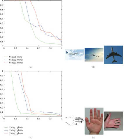
Figure14: Precision/recall plot for different photo sets (fishandteddyclasses) queried on the Watertight dataset (Setting includes 3 views, our alignment and pruning withk=50).
{Ci},{Cj}as
SP,G= 1
Ns
Ns
i=1
DSWCi,Ci
, (2)
here Ns is the number of silhouettes per probe image (in
practice,Ns=3 or 9, seeSection 5).
Silhouette matching is performed using dynamic pro-gramming. Given two curvesCi,Ci, a matching
pseudodis-tance, denoted DSW, is obtained as a sequence of operations (substitution, insertion, and deletion) which transformsCi
intoCi[43]. Considering theNsamples fromCi,Ciand the
underlying local convexity/concavity coefficientsF,F⊂RK,
the DSW pseudodistance is
DSWCi,Ci
= 1
N
N
u=1
Fu−Fg(u)1, (3)
here r1 =
i|ri| denotes the L1-norm, Fu ∈ F and
g : {1,. . .,N} → {1,. . .,N} is the dynamic
program-ming matching function, which assigns for each curvilinear abscissauinCiits corresponding abscissag(u) inCi. Given
0 0.2 0.4 0.6 0.8 1 0
0.1 0.2 0.3 0.4 0.5 0.6 0.7 0.8 0.9
Using1 sketch Using2 sketches Using3 sketches 1
(a) (b)
0 0.2 0.4 0.6 0.8 1
0 0.1 0.2 0.3 0.4 0.5 0.6 0.7 0.8 0.9
Using1 sketch Using2 sketches Using3 sketches 1
(c) (d)
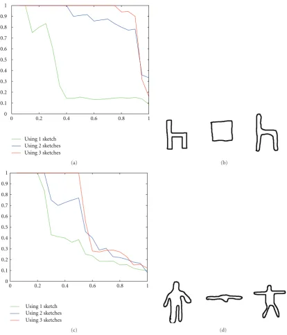
Figure15: Precision/recall plot for different hand-drawn sketches (chairand humanclasses) queried on the Watertight dataset (Setting includes 3 views, our alignment and pruning withk=50).
minimizes the number of operations (substitution, deletion, and insertion in order to transformCiintoCi) and preserves
the ordering assumption (i.e., ifuis matched withuthen
u+ 1 should be matched only withu+l,l >0). We introduce a variant of the standard dynamic programming; instead of examining all the possible matches, we consider only those which belong to a diagonal band ofD, that is,lis allowed to take only small values (see Figures7and8).
Dynamic programming pseudodistance provides a good discrimination power and may capture the intraclass variations better than the global distance (discussed in Section 4.1). Nevertheless, it is still computationally
expensive but when combined with coarse pruning the whole process is significantly faster and also precise (see
Figure 9andTable 2). Finally, this elastic similarity measure allows us to achieve retrieval while being robust to intraclass object articulations/deformations (observed in the Shrec Watertight set) and also to other effects (including noise) induced by hand-drawn sketches (see Figures14,15,16, and
17).
Runtime. Using the coarse-to-fine querying scheme
0 0.2 0.4 0.6 0.8 1 0
0.1 0.2 0.3 0.4 0.5 0.6 0.7 0.8 0.9
Using1photo Using2photos Using3photos 1
(a) (b)
0 0.2 0.4 0.6 0.8 1
0 0.1 0.2 0.3 0.4 0.5 0.6 0.7 0.8 0.9
Using1photo Using2photos Using3photos 1
(c) (d)
Figure16: Precision/recall plot for different photo sets (commercialandhandclasses) queried on the Princeton dataset (Setting includes 3 views, our alignment and Pruning withk=50).
to the fraction of nearest neighbors (according to our global descriptor) used in order to achieve dynamic programming. Lower values ofkmake the retrieval process very fast at the detriment of a slight decrease of precision and vice versa.
Figure 9shows runtime performance with respect to k on the same hardware platform (with 9 views).
5. Experiments
5.1. Databases. In order to evaluate the robustness of the proposed framework, we used two datasets. The first one is the Watertight dataset of the Shrec benchmark while the
second one is the Princeton Shape Benchmark, widely used in the 3D content-based retrieval community.
0 0.2 0.4 0.6 0.8 1 0
0.1 0.2 0.3 0.4 0.5 0.6 0.7 0.8 0.9
Using1 sketch Using2 sketches Using3 sketches 1
(a) (b)
0 0.2 0.4 0.6 0.8 1
0 0.1 0.2 0.3 0.4 0.5 0.6 0.7 0.8 0.9
Using1 sketch Using2 sketches Using3 sketches 1
(c) (d)
Figure17: Precision/recall plot for different hand-drawn sketches (glass with stemand eyeglassesclasses) queried on the Princeton dataset (Setting includes 3 views, our alignment and pruning withk=50).
Princeton Shape Benchmark. This dataset contains 907 “3D” objects organized in 92 classes. This dataset offers a large variety of objects for evaluation.
For the two datasets, each 3D object belongs to a unique class among different semantic concepts with strong variations including human, airplane, chair, and so forth. For instance, the human class contains persons with different poses and appearances “running, seating, walking, etc.”, globally the two databases are very challenging.
5.2. Evaluation Criteria. We evaluated our method using recall-precision. Precision is defined as the fraction of
relevant retrieved objects over the number of displayed 3D models while recall is defined as the fraction of relevant retrieved objects over the total number of relevant 3D models in the dataset. A plot that approaches the 1-1 corner indicates better retrieval results. In addition to recall/precision plot, we use several quantitative statistics to evaluate the results.
(i)The nearest neighbor (NN). It represents the fraction of the first nearest neighbors which belong to the same class as the query.
Photography silhouette queries
3D Hand-drawn sketch query
Figure18: Retrieval results with different scenarios, sketch, photos, and 3D models. In case of photos, queries may correspond to one or multiple views of the same or different objects.
class as the query that appear in thekbest matches. For a given classC containing |C|objects, k is set to|C| −1 for the first-tier measure whilekis set to 2(|C| −1) for second-tier (ST).
(iii) Finally, we usethe discounted cumulative gain (DCG)
measure which gives more importance to well-ranked models. Given a query and a list of ranked objects, we define for each ranked object a variableri equal to
1 if its class is equal to the class of the query and 0 otherwise. The DCG measure is then defined as.
DCGi=
⎧ ⎪ ⎨ ⎪ ⎩
DCGi−1 + ri
log2(i) if (i /=1),
ri otherwise.
(4)
We take the expectation of these measures on the entire database, that is, by taking all the possible object queries.
5.3. Performance and Discussion
Alignment. Figure 10shows the performance of our align-ment method presented in Section 2 on the Watertight dataset. For that purpose, we define a ground truth, by manually aligning 100 “3D” models5(20 categories each one has 5 objects) in order to make their canonical views parallel to the canonical planesxy,xz, and yz(seeFigure 11,ε=0 and alsoFigure 4). The error is then defined as the deviation (angle in degrees or radians) of the automatically aligned objects w.r.t. the underlying ground truth (see Figure 11,
ε=5,. . ., 20).
Different alignment methods were compared including the classic (PCA), normal PCA (NPCA), and our method.
Table5: This table shows performance and comparisons, on the Shape Princeton Benchmark. Our method is shown in bold under the name MCC (see [4,10,34] andTable 7).
Methods NN (%) FT (%) ST (%) DCG (%)
MCC 3 71.9 47.2 58.6 71.5
MCC 2 71.9 45.1 55.6 70.1
MCC 4 67.1 39.8 51 66.1
MCC 1 65.9 39.4 50.7 65.8
LFD 65.7 38 48.7 64.3
EDBA 65.4 38.3 49.8 64.1
AVC 62 35.5 45.5 63
ESA 57.8 32.6 44.4 60.2
REXT 60.2 32.7 43.2 60.1
DBD 59.2 32.9 41.8 58.9
SHD 55.6 30.9 41.1 58.4
GEDT 60.3 31.3 40.7 58.4
SIL 52.8 28.5 38.8 56.3
EXT 54.9 28.6 37.9 56.2
SECSHEL 54.6 26.7 35 54.5
VOXEL 54 26.7 35.5 54.3
SECTORS 50.4 24.9 33.4 52.9
CEGI 42 21.1 28.7 47.9
EGI 37.7 19.7 27.7 47.2
D2 31.1 15.8 23.5 43.4
SHELLS 22.7 11.1 17.3 38.6
Table6: This table shows the evolution of the NN, FT, ST, and DCG measures (in %) for photos and hand-drawn sketches queries. Each row corresponds, respectively, to the query presented in Figures14 to17with 1, 2, and 3 views per query.
Query Number of
views NN (%) FT (%) ST (%) DCG (%)
Watertight-Photos-Fish
1 0 35 60 55
2 100 65 85 83.2
3 100 80 85 95.8
Watertight-Photos-Teddy
1 0 15 55 50.8
2 100 55 80 76.6
3 100 65 75 91.5
Watertight-Sketches-Chair
1 100 30 35 74.3
2 100 80 90 96.5
3 100 90 90 97.8
Watertight- Sketches-Human
1 100 40 50 79.7
2 100 50 60 86.1
3 100 55 55 89.1
Princeton- Photos-Commercial
1 100 45.4 45.4 75.6
2 100 45.4 63.6 84
3 100 54.5 63.6 87.8
Princeton-Photos-Hand
1 100 17.6 23.5 61.3
2 100 35.3 35.3 75.1
3 100 41.2 41.2 75.4
Princeton-Sketches-Glass with stem
1 100 44.4 44.4 70
2 0 66.7 66.7 76.7
3 0 77.8 88.9 83.5
Princeton- Sketches-Eyeglasses
1 0 28.6 28.6 38.6
2 0 28.6 28.6 58.8
3 100 57.1 57.1 82.7
automatically and correctly aligned up to an angleεw.r.t. the underlying 3D models in the ground truth.
Table 2illustrates the statistics defined earlier. We clearly see that our new alignment method gives better results compared to the classical PCA and NPCA. Again our pose estimation method makes it possible to extract several canonical 2D views and for each one we compared results using either three or nine 2D views per object (see results in Figure 13 and rows 4 and 5 of Table 2). Regarding the influence of the number of views, the performances increase for the two datasets.
Coarse-to-Fine Retrieval. In order to control/reduce the runtime to process and match local signatures, we used our pruning approach based on the global signature discussed in
Section 4.1. The parameterkallows us to control the trade-offbetween robustness and speed of the retrieval process. A small value of kgives real-time (online) responses with an acceptable precision while a high value requires more pro-cessing time but gives better retrieval performance.Figure 12
shows the NN, FT, ST, and DCG measures for different pruning thresholds k.Table 2 shows different statistics for
k=0, 50, and max.
Table 7: This table describes the significance of different acronyms/methods which participate in the Watertight and the Princeton benchmarks.
CSID-CMVD 1, 2, 3
Compact shape impact descriptor and multi view descriptor [1]
MRSPRH-UDR Unsupervised dimension reduction approach [1] BFSIFT Bag-of-local visual feature [1] ERG 1, 2 Enhanced reeb graph [1] BOW, CBOW (Concentric) bag of words [1] LFD Light field descriptor [12–14]
EDBA Enhanced depth buffer approach
[10]
AVC Adaptive view clustering [15]
ESA Enhanced silhouettes approach
[10]
REXT Radialized spherical extent
function [38]
DBD Depth buffer descriptor [39]
SHD Spherical harmonic descriptor
[23]
GEDT Gaussian euclidean distance
transform [23]
SIL Silhouettes approach [39]
EXT Spherical extent function [33]
SECSHEL Shape histogram [3]
VOXEL 3D shape voxelization [39]
SECTORS Shape histogram [3]
CEGI Complex extended gaussian
image [22]
EGI Extended gaussian image [20]
D2 D2 shape distribution [31]
SHELLS Shape histogram [3]
Table 3 shows also the performance of matching using dynamic programming versus adhoc naive matching (i.e., through the curvilinear abscissa,g(u) =uin (2). Dynamic programming outperforms the naive matching by allowing
g(u) to be equal to u+ l (l > 0) in contrast to naive matching (l=0); this clearly makes dynamic programming more flexible in order to handlelocaldeformations (see again
Table 3).
5.4. Benchmarking and Comparison
a global measure which provides us with the overall retrieval performance.
We submitted in this benchmark four runs.
(i) Run 1 (MCC 1): 9 silhouettes and pruning threshold
k=0. The average runtime for each query is 0.03 s.
(ii) Run 2 (MCC 2): 9 silhouettes and pruning threshold
k=50. The average runtime for each query is 9.4 s.
(iii) Run 3 (MCC 3): 9 silhouettes and pruning threshold
k=200. The average runtime for each query is 36.2 s.
(iv) Run 4 (MCC 4): 3 silhouettes and pruning threshold
k=50. The average runtime for each query is 3.1 s.
We can see in Table 4 that the third run of our method (shown in bold) outperforms the others for the first-tier and is equivalent to the C SID CMVD 3 for the second-tier (see
Table 7for the significance of method acronyms). The results for the second run are similar to the BF SIFT 1 and to the C SID CMVD 1 methods.
Princeton Shape Benchmark Dataset. Table 5 shows a com-parison of the four runs of our approach on the Princeton Shape Benchmark; these runs outperform the other partici-pating methods (described in [4,10,34]).
Hand-Drawn Sketches and Photos. Finally, we compared our approach with respect to two querying schemes including (i) 2 hand-drawn sketches per mental category6 or (ii) silhouettes from multiview real pictures. In both scenarios, gallery data are processed in the same way as inTable 4(MCC 4), that is, by aligning 3D objects using our pose estimation method and processing them in order to extract 3 views. The results on the two databases, in Figures14to17,Table 6and
Figure 18, show very encouraging performances on real data (sketches and real pictures) and clearly open very promising directions for further extensions and improvements.
6. Conclusion
We introduced in this paper a novel and complete frame-work for “2D-to-3D” object retrieval. The method makes it possible to extract canonical views using a generative approach combined with principal component analysis. The underlying silhouettes/contours are matched using dynamic programming in a coarse-to-fine way that makes the search process efficient and also effective as shown through exten-sive evaluations.
One of the major drawbacks of dynamic programming resides in the fact that it is not a metric, so one cannot benefit from lossless acceleration techniques which provide precise results and efficient computation. Our extension is to tackle this issue by introducing new matching approaches that allow us to speedup the search process while keeping high precision.
Acknowledgment
This work was supported by the European Network of Excellence KSpace and the French National Research Agency (ANR) under the AVEIR Project, ANR-06-MDCA-002.
Endnotes
1. Even though in a chaotic way because of the absence of consistent alignments of 3D models.
2. Obviously, normalization is achieved on the probe set only when queries are 3D models. As for the 2D photo or the sketch scenarios, one assumes that at least three silhouettes are available corresponding to three canonical views.
3. Again, this is in accordance with cognitive psychology of human perception (defined, e.g., in [25]).
4. The initial object pose is assumed to be the canonical one.
5. http://perso.enst.fr/∼sahbi/file/Watertight Alignment GroundTruth.zip.
6. The user will imagine a category existing in the Water-tight gallery set and will draw it.
References
[1] J. Hartveldt, M. Spagnuolo, A. Axenopoulos, et al., “SHREC’09 track: structural shape retrieval on watertight models,” in Proceedings of Eurographics Workshop on 3D Object Retrieval, pp. 77–83, Munich, Germany, March 2009.
[2] T. Adamek and N. E. O’Connor, “A multiscale representation method for nonrigid shapes with a single closed contour,” IEEE Transactions on Circuits and Systems for Video Technology, vol. 14, no. 5, pp. 742–753, 2004.
[3] M. Ankerst, G. Kastenm¨uller, H. P. Kriegel, and T. Seidl, “Nearest neighbor classification in 3D protein databases,” in Proceedings of the 7th International Conference on Intelligent Systems for Molecular Biology (ISMB ’99), pp. 34–43, Heidel-berg, Germany, August 1999.
[4] T. F. Ansary,Model retrieval using 2d characteristic views, Ph.D. thesis, 2006.
[5] R. Bellman, “Dynamic programming,”Science, vol. 153, no. 3731, pp. 34–37, 1966.
[6] S. Biasotti, D. Giorgi, S. Marini, M. Spagnuolo, and B. Falci-dieno, “A comparison framework for 3D object classification methods,” in Proceedings of the International Workshop on Multimedia Content Representation, Classification and Security (MRCS ’06), vol. 4105 ofLecture Notes in Computer Science, pp. 314–321, 2006.
[7] S. Biasotti, S. Marini, M. Spagnuolo, and B. Falcidieno, “Sub-part correspondence by structural descriptors of 3D shapes,” Computer Aided Design, vol. 38, no. 9, pp. 1002–1019, 2006. [8] A. Del Bimbo and P. Pala, “Content-based retrieval of
3D models,” ACM Transactions on Multimedia Computing, Communications and Applications, vol. 2, no. 1, pp. 20–43, 2006.
3D Data Processing, Visualization, and Transmission, pp. 215– 222, IEEE Computer Society, Thessaloniki, Greece, September 2004.
[10] M. Chaouch and A. Verroust-Blondet, “Enhanced 2D/3D approaches based on relevance index for 3D-shape retrieval,” in Proceedings of IEEE International Conference on Shape Modeling and Applications (SMI ’06), p. 36, Matsushima, Japan, June 2006.
[11] M. Chaouch and A. Verroust-Blondet, “A new descriptor for 2D depth image indexing and 3D model retrieval,” inProceedings 14th IEEE International Conference on Image Processing (ICIP ’07), vol. 6, pp. 373–376, September 2006. [12] D. Chen, Three-dimensional model shape description and
retrieval based on lightfield descriptors, Ph.D. thesis, Depart-ment of Computer Science and Information Engineer, National Taiwan University, Taipei, Taiwan, June 2003. [13] D. Chen and M. Ouhyoung, “A 3d model alignment and
retrieval system,” inProceedings of the International Workshop on Multimedia Technologies, pp. 1436–1443, December 2002. [14] D.-Y. Chen, X.-P. Tian, Y.-T. Shen, and M. Ouhyoung, “On
visual similarity based 3D model retrieval,”Computer Graphics Forum, vol. 22, no. 3, pp. 223–232, 2003.
[15] T. F. Ansary, M. Daoudi, and J.-P. Vandeborre, “A Bayesian 3-D search engine using adaptive views clustering,” IEEE Transactions on Multimedia, vol. 9, no. 1, pp. 78–88, 2007. [16] K. Fischer and B. G¨artner, “The smallest enclosing ball of balls:
combinatorial structure and algorithms,”International Journal of Computational Geometry and Applications, vol. 14, no. 4-5, pp. 341–378, 2004.
[17] T. Funkhouser, P. Min, M. Kazhdan, et al., “A search engine for 3D models,”ACM Transactions on Graphics, vol. 22, no. 1, pp. 83–105, 2003.
[18] T. Funkhouser and P. Shilane, “Partial matching of 3d shapes with priority-driven search,” inProceedings of the 4th Eurographics Symposium on Geometry Processing, pp. 131–142, Cagliari, Italy, June 2006.
[19] M. Hilaga, Y. Shinagawa, T. Kohmura, and T. L. Kunii, “Topology matching for fully automatic similarity estimation of 3D shapes,” inProceedings of the 28th Annual Conference on Computer Graphics and Interactive Techniques (SIGGRAPH ’01), pp. 203–212, Los Angeles, Calif, USA, August 2001. [20] B. K. P. Horn, “Extended Gaussian images,”Proceedings of the
IEEE, vol. 72, no. 12, pp. 1671–1686, 1984.
[21] H. Jin, S. Soatto, and A. J. Yezzi, “Multi-view stereo reconstruc-tion of dense shape and complex appearance,”International Journal of Computer Vision, vol. 63, no. 3, pp. 175–189, 2005. [22] S. B. Kang and K. lkeuchi, “Determining 3-d object pose using
the complex extended Gaussian image,” inProceedings of the IEEE Computer Society Conference on Computer Vision and Pattern Recognition, pp. 580–585, Maui, Hawaii, USA, June 1991.
[23] M. M. Kazhdan, T. A. Funkhouser, and S. Rusinkiewicz, “Rotation invariant spherical harmonic representation of 3d shape descriptors,” in Proceedings of the Eurographics/ACM SIGGRAPH Symposium on Geometry Processing (SGP ’03), pp. 156–165, Eurographics Association, Aachen, Germany, June 2003.
[24] H. Laga, H. Takahashi, and M. Nakajima, “Spherical wavelet descriptors for content-based 3D model retrieval,” in Proceed-ings of IEEE International Conference on Shape Modeling and Applications (SMI ’06), p. 15, Matsushima, Japan, June 2006. [25] E. C. Leek, “Effects of stimulus orientation on the
identifica-tion of common polyoriented objects,”Psychonomic Bulletin and Review, vol. 5, no. 4, pp. 650–658, 1998.
[26] S. Mahmoudi and M. Daoudi, “3D models retrieval by using characteristic views,” inProceedings of the 16th International Conference on Pattern Recognition (ICPR ’02), no. 2, pp. 457– 460, Quebec, Canada, August 2002.
[27] NIST, “Shape retrieval contest on a new generic shape bench-mark,” 2004, http://www.itl.nist.gov/iad/vug/sharp/bench-mark/shrecGeneric/Evaluation.html.
[28] M. Novotni and R. Klein, “3D Zernike descriptors for content based shape retrieval,” inProceedings of the 8th Symposium on Solid Modeling and Applications, pp. 216–225, ACM Press, Seattle, Wash, USA, 2003.
[29] R. Ohbuchi and J. Kobayashi, “Unsupervised learning from a corpus for shape-based 3D model retrieval,” inProceedings of the ACM International Multimedia Conference and Exhibition, pp. 163–172, Santa Barbara, Calif, USA, October 2006. [30] R. Ohbuchi, M. Nakazawa, and T. Takei, “Retrieving 3d shapes
based on their appearance,” inProceedings of the 5th ACM SIGMM International Workshop on Multimedia Information Retrieval (MIR ’03), N. Sebe, M. S. Lew, and C. Djeraba, Eds., pp. 39–45, 2003.
[31] R. Osada, T. Funkhouser, B. Chazelle, and D. Dobkin, “Match-ing 3d models with shape distributions,” inProceedings of the International Conference on Shape Modeling and Applications (SMI ’01), B. Werner, Ed., pp. 154–166, IEEE Computer Society, Los Alamitos, Calif, USA, May 2001.
[32] P. Papadakis, I. Pratikakis, S. Perantonis, T. Theoharis, and G. Passalis, “SHREC’08 entry: 2D/3D hybrid,” inProceedings of IEEE International Conference on Shape Modeling and Applications (SMI ’08), pp. 247–248, June 2008.
[33] D. Saupe and D. V. Vranic, “3d model retrieval with spherical harmonics and moments,” inProceedings of the 23rd DAGM-Symposium on Pattern Recognition, B. Radig and S. Florczyk, Eds., vol. 2191 ofLecture Notes in Computer Science, pp. 392– 397, Springer, 2001.
[34] P. Shilane, P. Min, M. Kazhdan, and T. Funkhouser, “The Princeton shape benchmark,” in Proceedings of the Shape Modeling International (SMI ’04), pp. 167–178, Washington, DC, USA, 2004.
[35] J. W. H. Tangelder and R. C. Veltkamp, “A survey of content based 3D shape retrieval methods,” inProceedings of the Shape Modeling International (SMI ’04), pp. 145–156, June 2004. [36] J. Tierny, J.-P. Vandeborre, and M. Daoudi, “3d mesh skeleton
extraction using topological and geometrical analyses,” in Proceedings of the 14th Pacific Conference on Computer Graphics and Applications, pp. 85–94, Taipei, Taiwan, October 2006. [37] T. Tung and F. Schmitt, “The augmented multiresolution Reeb
graph approach for content-based retrieval of 3D shapes,” International Journal of Shape Modeling, vol. 11, no. 1, pp. 91– 120, 2005.
[38] D. V. Vrani´c, “An improvement of rotation invariant 3D-shape descriptor based on functions on concentric spheres,” in Proceedings of IEEE International Conference on Image Processing, vol. 3, pp. 757–760, 2003.
[39] D. V. Vranic,3D model retrieval, Ph.D. thesis, University of Leipzig, 2004.
[40] D. V. Vrani´c, D. Saupe, and J. Richter, “Tools for 3D-object retrieval: Karhunen-Loeve transform and spherical harmonics,” in Proceedings of the 4th IEEE Workshop on Multimedia Signal Processing, J.-L. Dugelay and K. Rose, Eds., pp. 293–298, Budapest, Hungary, September 2001.
[42] D. Zarpalas, P. Daras, A. Axenopoulos, D. Tzovaras, and M. G. Strintzis, “3D model search and retrieval using the spherical trace transform,” EURASIP Journal on Advances in Signal Processing, vol. 2007, Article ID 23912, 14 pages, 2007. [43] J. Tierny, J.-P. Vandeborre, and M. Daoudi, “Invariant high