ORIGINAL ARTICLE
Method for measuring the resistances
produced on parallel and perpendicular veneers
in plywood under nail embedment loading
Keita Ogawa
*, Masaki Harada, Tatsuya Shibusawa and Kohta Miyamoto
Abstract
The resistance of wooden materials against embedment loading is an important property that governs the perfor-mance of timber joints with dowel-type fasteners including nails. When plywood is used as a sheet material in a nailed joint, veneers with different grain directions are simultaneously embedded. The resistance produced on individual veneers has to be measured to elucidate the embedment properties of plywood. This study proposes a method for measuring resistance on individual veneers. Embedment behavior was modeled using springs arranged in parallel, and the equations for calculating resistance on individual veneers were derived. Embedment tests were conducted using structural plywood composed of sugi or karamatsu. Mechanical behaviors of individual veneers were revealed as followings. In the initial range of deformation, the slope of the resistance–deformation relationship of the veneer with grain parallel to the load direction is higher than that of the resistance–deformation relationship of the veneer with grain perpendicular to the load direction. The parallel veneer began to yield under a low range of deformation, and the resistance of the perpendicular veneer under a high range of deformation became almost equal to that of the parallel veneer.
Keywords: Plywood, Embedment, Nail, Load–deformation relationship, Spring model
© The Author(s) 2019. This article is distributed under the terms of the Creative Commons Attribution 4.0 International License (http://creat iveco mmons .org/licen ses/by/4.0/), which permits unrestricted use, distribution, and reproduction in any medium, provided you give appropriate credit to the original author(s) and the source, provide a link to the Creative Commons license, and indicate if changes were made.
Introduction
Plywood-sheathed structural diaphragms with nailed joints are commonly used in the construction of light wooden frames or other types of structures. Past stud-ies have shown that the in-plane shear resistance per-formance of the diaphragms is mainly dominated by the shear performance of the nailed joints [1–4]. The embed-ment behavior of wood by a nail is an important charac-teristic that strongly influences the shear performance of the joints. This characteristic has been used to analyze or predict shear performances on the basis of European Yield Theory [5, 6], elastic foundation model [7–12], and finite element method [13–15]. Therefore, the embed-ment behavior of wood and wood-based materials by a nail must be clarified. The embedment behaviors of vari-ous types of wooden materials by dowel-type fasteners
have been investigated under different loading condi-tions. For example, Chui and Ni [16] conducted embed-ment tests on spruce, maple, and plywood specimens under reversed cyclic load. Jeon and Kong [17] evalu-ated the embedment behavior of glulam specimens made of Japanese cedar by ash pegs. Bal [18] investigated the characteristics of plywood reinforced with glass fiber fabric. Sawata and Sasaki [19] evaluated the embedment properties of decay-treated solid wood specimen.
When the load is applied to the structural diaphragms with nailed joints, the joints are loaded from many angles. Then, the influence of the grain direction of wood or wood-based material on the embedment behavior is of major concern. Jeong et al. [20] subjected glulam specimens made of Japanese cedar to embedment tests. They applied load on longitudinal, radial, and tangen-tial directions and obtained the highest load capacity in the longitudinal direction. Bleron et al. [21] investigated the embedment characteristics of a gonfolo rose speci-men with various grain directions. Under embedspeci-ment
Open Access
*Correspondence: [email protected]
load applied perpendicular to the grain direction, lower load at plastic threshold and higher maximum load were observed than the case of parallel.
Plywood is a wood-based panel material produced by alternately laminating veneers with parallel and per-pendicular grain directions. The grain direction of each veneer may affect embedment behavior in plywood– solid wood nail joints. On the shear performance of ply-wood–solid wood nailed joints, the effect of the grain direction of plywood has been investigated under sin-gle-shear loading. Stewart [22] conducted a single-shear test with nailed joint specimens. He prepared two types of plywood joint specimens. In the joint specimes, the plywood was attached to become that the grain direc-tion of surface veneer were parallel or perpendicular to the load direction. The load–deformation curves of the two types of specimens were not considerably differ-ent. Harada et al. [23] conducted the tests with similar types of specimen and reported no large difference in maximum load. However, the deformation at maximum load in the case of plywood with perpendicular grain of the surface veneer was higher than that of parallel grain. Meanwhile, Demirkir and Colakoglu [24] reported that stiffness was higher when the surface direction of ply-wood was parallel to the loading direction than when the surface direction of plywood was perpendicular to the loading direction. Hagiwara [25] reported no difference in shear performance between the parallel and perpen-dicular grain directions of plywood. However, when the angle between the grain and load directions was 30°, 45° or 60°, resistance performance decreased under a small load range.
The resistance of nailed joints under single-shear loading is determined by various factors, e.g., bending properties of nail, pull out strength of nail from wood, nail-head pull-through resistance. In addition, the com-bination of plywood embedment and solid wood embed-ment resistances is also one of the important factors for it; however, the above studies [22–25] did not ignore the
resistance produced by solid wood. The authors posit that only the resistance produced in plywood should be considered to clarify the influence of the grain direction of plywood. Some studies have conducted embedment tests on plywood specimens [18, 26, 27], and Kamada [28] showed the experimental data of the two grain direc-tions (i.e., the grain direction of surface veneer was par-allel or perpendicular to the load direction) using 3-ply plywood made of larch. According to his data, the higher stiffness was observed when the grain direction of sur-face veneer was parallel to the loading direction, whereas almost same maximum load was observed in the two. In this study, an embedment test was conducted on ply-wood specimens with grain directions of surface veneers that are parallel and perpendicular to the load direction. Moreover, to understand the resisting mechanism of plywood precisely, the method for calculating the resist-ance–deformation relationship exhibited by individual parallel and perpendicular veneers was proposed.
Materials and methods Plywood specimen
Structural plywood made of sugi (Japanese cedar, Cryp-tomeria japonica D. Don) and karamatsu (Japanese larch,
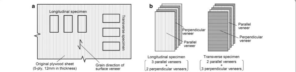
Larix kaempferi Carr.) classified as Class 2 structural plywood in accordance with the Japanese Agricultural Standard [29] was used as the specimen. The plywood was made in Japan and had five plies and a thickness of 12 mm. Eight original sheets were produced by prepar-ing four sheets from each species. Six specimens meas-uring 50 mm × 100 mm in size were removed from the original sheets. From one original sheet, three specimens with grain in the surface veneer parallel to the specimen’s longitudinal direction (hereafter, longitudinal specimen) and three specimens with grain in the surface veneer parallel to the specimen’s transverse longitudinal direc-tion (transverse specimen) were obtained as shown in Fig. 1a. The provided original plywood sheets were com-posed of veneers with grain parallel and perpendicular to
the load direction (hereafter, parallel and perpendicular veneer). The composition of longitudinal and transverse specimens is shown in Fig. 1b. Table 1 presents the four series of specimens. The total number of specimens was 48. These specimens had been placed in a conditioning testing room at 20 °C and 65% relative humidity for more than 1 month. The sugi plywood specimen had a density of 423 ± 22 kg/m3 (average ± standard deviation) and
moisture content of 10.3 ± 0.3%; whereas, the karamatsu plywood specimen had a density of 626 ± 24 kg/m3 and
moisture content of 10.1 ± 0.3%.
Embedment test
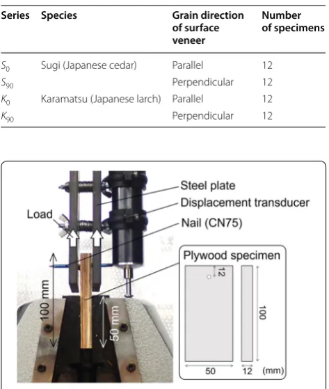
The embedment test was conducted in accordance with the American Society for Testing Materials (ASTM) standard D1037-12 [30]. However, the specimen size was different from that recommended by the standard method. The experimental setup is shown in Fig. 2. A CN75 nail [31] with a trunk diameter of 3.76 mm was driven into the specimen at a point 12 mm below the top side. The specimen was set to an Instron-type ten-sion–compression testing machine (MinebeaMitsumi, Inc., (formerly Shinko Co., Ltd.), TOM-5000X; capacity: 49.5 kN). The nail part of the specimen was hooked to the holes with diameter of 10 mm installed to two steel
plates, and the gaps between the plates and plywood were maintained at 1 mm. The plywood part was grabbed with a chuck. The embedment load by the nail was applied to the plywood by moving up the steel plates. The load was measured with a load cell (MinebeaMitsumi, Inc., (for-merly Shinko Co., Ltd.), TT3-5T; capacity: 49.5 kN), and deformation was measured with a displacement trans-ducer (Tokyo Sokki Kenkyujo Co., Ltd., CDP-50, capacity 50 mm) connected to the steel plate (Fig. 2). The grabbed length in this setup exceeded 50 mm. In this grabbed length, the slip that occurred around the chuck was too small and the slip was ignored in the analysis. Load was applied at the speed of 0.5 mm/min. After reaching the maximum load, load was continuously applied until it decreased to 80% of the maximum.
Results and discussion Embedment test results
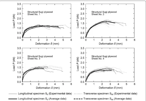
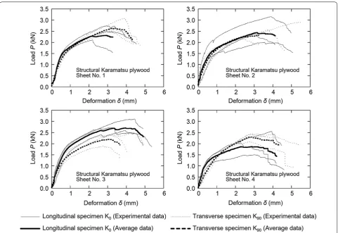
Figures 3 and 4 present the load–deformation relation-ships. Each graph shows the results for three longitudinal and three transverse specimens obtained from one origi-nal structural plywood. The solid lines represent the lon-gitudinal specimens (Series S0 in Fig. 3 and Series K0 in
Fig. 4), whereas the dotted lines represent the transverse specimens (Series S90 in Fig. 3 and Series K90 in Fig. 4).
The thin lines denote the experimental results, whereas the thick lines denote the average results obtained by averaging the value of the load of the three specimens under the same deformation. Comparing the averaged results of longitudinal and transverse specimens (solid and dotted thick lines) revealed that the longitudinal specimen has a slightly larger load value than the trans-verse specimen in the rage from the beginning of the testing to approximately 1 mm in deformation. The dif-ference in the load value decreased as the deformation increased.
Failure mode observed around nail part is illustrated in Fig. 5. An embedment deformation was observed in par-allel and perpendicular veneers. At the end of the loading, in parallel veneer, trapezoidal failure occurred; whereas in perpendicular veneer, only the embedment deforma-tion was observed. The failure modes were observed in both longitudinal and transverse specimens.
Stiffness and maximum load were calculated from the load–deformation relationships of all the specimens. Stiffness was derived as the slope with linear regression to the data plots in the range of 10–40% maximum load through the least-squares method. Figure 6 depicts the average values and the standard deviations of stiffness and maximum load. For example, the average stiffness of Series S0 was 3.23 kN/mm, whereas that of Series S90
was 1.99 kN/mm, which was considerably lower than that of S0. In the case of Series K0 and K90, average values of
Table 1 Series of plywood specimens
Series Species Grain direction
of surface veneer
Number of specimens
S0 Sugi (Japanese cedar) Parallel 12
S90 Perpendicular 12
K0 Karamatsu (Japanese larch) Parallel 12
K90 Perpendicular 12
stiffness were 3.24 and 2.25 kN/mm, respectively, which also had a large difference between the two. The calcu-lation of the t-test showed that there were significant differences in stiffness between S0–S90 and K0–K90 at a
significance level of 0.05. However, the average maximum load of series S0 and S90 was 1.45 and 1.49 kN, indicating
that the two series provide an almost equal value of maxi-mum load. Similar results were observed for the kara-matsu plywood: maximum loads of K0 and K90 were 2.45
and 2.47 kN, respectively. The calculation of the t-test showed that there were no significant differences in max-imum load between S0–S90 and K0–K90 at a significance
level of 0.05. The results indicated that the grain direc-tion of the surface veneer considerably affects stiffness but negligibly affects maximum load under embedment resistance.
Method for calculating the load–deformation relationships of parallel and perpendicular veneers
To understand the embedment behavior of plywood precisely, this section describes a method for calculat-ing the resistance produced on individual veneers under
embedment loading. This method uses the load–defor-mation relationships shown in Figs. 3 and 4. Figure 7
shows the model of specimen deformation under nail embedment load. The model was constructed with springs. Figure 7a shows the schematic of the nail region of the specimen. The nail was embedded in the plywood by moving up the steel plates. In the case that the ply-wood is sufficiently thin, two assumptions could be imposed on the model: First, the nail is bent at the wood surface. Second, the shape of the nail in the ply-wood remains linear (i.e., embedment deformation is equal in the five veneers).
On the basis of these assumptions, the specimen was modeled with springs (Fig. 7b). The read value from the displacement transducer (Fig. 2) includes two deforma-tions: the bending deformation of the nail [(A), Fig. 7b] and the embedment deformation of the plywood [(B), Fig. 7b]. The read value from the displacement trans-ducer deformation δ is the sum of the bending deforma-tion of the nail δnail and the embedment deformation of
the plywood δply:
(1) δ=δnail+δply
Therefore, the relationship between load P and the embedment deformation of the plywood δply [i.e., only
the relationship in part (B)] could be calculated by obtaining the bending deformation of the nail δnail.
The five springs in the model of the embedment deformation of plywood indicate that each veneer was arranged in parallel. Here, the load value of the longi-tudinal specimen at deformation δply was denoted as
Pply.0. Similarly, the load value of the transverse
speci-men at deformation δply (same deformation with the case
of Pply.0) was denoted as Pply.90. If the thicknesses of five
veneers was equal, the two load values could be repre-sented with the nail embedment resistances produced on the parallel Rven.0 and perpendicular Rven.90 veneers as
follows:
The resistances Rven.0 and Rven.90 under the embedment
deformation of plywood δply are represented as the
simul-taneous solution to Eqs. (2) and (3) as follows:
(2)
Pply.0=3Rven.0+2Rven.90
(3)
Pply.90=2Rven.0+3Rven.90
(4)
Rven.0= 3
Pply.0−2Pply.90
5 Fig. 4 Results of embedment test of nail in structural karamatsu plywood specimens (K0 and K90)
The relationships between the resistance and deforma-tion of each veneer could be obtained by calculating the resistances under various δply.
Figure 7 and Eqs. (2)–(5) were supposed that all of thickness of veneers in the provided plywood is equal. However, in the case that a plywood is applied sur-face smoothing, the assumption is not true because the thickness of surface veneer becomes thin. Although the Eqs. (4) and (5) cannot be used, the resistance produced at individual veneers can be calculated with alternative equations derived by the model similarly to the above.
(5)
Rven.90=
−2Pply.0+3Pply.90
5
For this, the thickness of individual should be measured. The resistance can be calculated by following equations with the sum of thickness of parallel veneers t0 and sum
of thickness of perpendicular veneers t90:
It should be noted that R′ven.0 and R′ven.90 in Eqs. (6) and (7) are the resistances per thickness.
Resistance–deformation behavior of each veneer
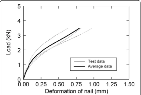
The relationship between the load and deformation behavior of each veneer was graphed by the experimental results and the proposed model. The bending deforma-tion of the nail has to be measured through an addideforma-tional test to enable analysis with the proposed method. The additional test was conducted in the same setup as shown in “Embedment test” of “Materials and methods” section (Fig. 2). The plywood was replaced with a steel plate hav-ing a hole (12 mm in thickness). Therefore, the nail was fixed by the three steel plates, and bent by moving up the two steel plates. During the test, the nail was deformed similarly to the case of using plywood, i.e., it could be assumed that the nail kept lineally at the contacted area between the nail and the replaced steel plate. Figure 8
shows the relationship between load P and deformation
δnail obtained through the test. The thin lines represent
the experimental data, whereas the thick line represents the averaged data. The deformation of the plywood δply
was calculated using the results of the embedment test (relationship between P and δ shown in Figs. 3 and 4) and the nail test (relationship between P and δnail shown in (6) R′
ven.0=
t0·Pply.0−t90·Pply.90
t2 0−t902
(7) R′ven.90=
−t90·Pply.0+t0·Pply.90
t2 0−t902
Fig. 6 Average values and the standard deviations of stiffness and maximum load obtained by the embedment test. *Significant difference observed at a significance level of 0.05
Fig. 7 A model of specimen deformation. a Schematic diagram of deformation. b A spring model
Fig. 8). Under the same load value P, the deformation of nail δnail (Fig. 8) was subtracted from the read value from
the displacement transducer δ (Figs. 3 and 4) to calculate the deformation of plywood δply [Eq. (1)]. The
relation-ship between load P and deformation δply was obtained
by calculating deformation δply under various load P
values.
The relationships between resistances Rven.0 and Rven.90
and the deformation δply of each veneer were calculated
on the basis of the relationships between load P and deformation δply (Load P was substituted to Pply.0 and
Pply.90 in the cases of longitudinal and transverse
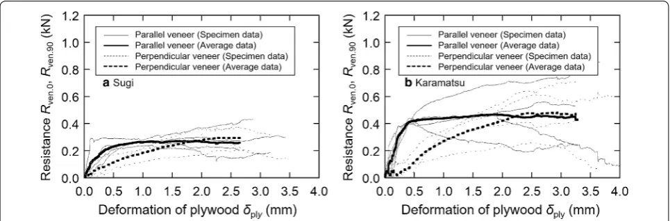
speci-mens, respectively) using Eqs. (4) and (5). Herein, the relationships were calculated for each original plywood sheet, i.e., the result obtained for one original sheet (shown as solid and dotted thick lines in Figs. 3 and 4) was used for calculation, and the results for other original sheets were calculated through the same method. Four results for the sugi plywood and four results for the kara-matsu plywood were obtained and are shown in Fig. 9. The solid lines denote the results for the parallel veneers, whereas the dotted lines denote those for the perpen-dicular veneers. The thin lines represent the calculated results for one original sheet, whereas the thick lines represent the averaged results obtained with the aver-age value of resistance under the same deformation in four solid/dotted thin lines. Although there is no signifi-cant variation in the relationships of plywood specimens (Figs. 3 and 4), the relationships in Fig. 9 have a wide vari-ation. The reason for it is assumed that Fig. 9 focused on the veneers having a characteristic in small thickness, i.e., it was discussed about resistance produced on very local area of wood. The subtle difference in wood properties (e.g., density, ring width, and so on) might influence the relationships of veneers largely. In the following, the rela-tionships of veneers were discussed with average results;
however, it is desired that the variation should be taken in consideration when discussing on the relationships in future study.
Comparing the results for parallel and perpendicular veneers (shown as solid and dotted thick lines) reveals that the resistance of the former had a larger slope than the that of the latter during the initial stage of the test. The slope of the parallel veneer began to become small gradually under approximately 0.3 mm of deforma-tion, then kept the resistance after it. The perpendicular veneer increased its resistance until under approximately 2.0 mm of deformation. The two thick lines intersected when deformation reached approximately 2.0 mm (i.e., no difference attributable to the resistance contributed by the grain direction of the veneer was observed under such a large deformation).
Next, the obtained behavior (Fig. 9) was discussed by comparing with past reports on the anisotropic strength properties of plywood. Asano and Tsuzuki [32] attempted to reveal the compression properties of veneer by con-ducting compression tests on Lauan plywood specimens. They reported that perpendicular veneer shows low modulus of elasticity and strength. This tendency was experimentally confirmed by Kuwamura [33], who sub-jected veneer specimens to an in-plane compression test under steel-plate loading and found that the compression strength of parallel veneer was approximately 7.5 times higher than that of perpendicular veneer. Although the resisting behavior in this study (Fig. 9) revealed the dif-ference between parallel and perpendicular veneers, the difference was not as large as the results of above reports [32, 33]. This result may be attributed to differences in loading conditions, loaded with steel plate or nail. Some researchers have reported [34, 35] that when fastener diameter is sufficiently small, the contribution of grain direction to differences in characteristics of embedment
behavior decreases. The diameter of the nail used in this study is small enough to reduce the influence of grain direction. This effect, in turn, may have resulted in the smaller differences than compression results obtained under steel-plate loading.
Conclusion
To analyze the mechanical properties of nailed joint, precisely understanding of the deformation around nail is important. This study conducted the nail embedment test with plywood specimens for comparing the behav-iors between different grain direction in surface veneer. Sugi and karamatsu plywood specimens with thick-nesses of 12 mm (5-ply) were loaded by a CN75 nail in accordance with the ASTM setup. This test revealed that the grain direction of the surface veneer considera-bly affects stiffness but negligiconsidera-bly affects maximum load under embedment resistance.
Additionally, the authors tried to calculate the resist-ing behavior produced on individual veneers. The pre-sented method clarifies the mechanical contribution of veneers with parallel and perpendicular grain to the resisting behavior of plywood under embedment load-ing by a nail, which helps to understand the deforma-tion of plywood in detail. The proposed method was developed on the basis of a plywood deformation model constructed with springs arranged in parallel. The experimental results showed that under low defor-mation, the parallel veneer had a higher slope than the perpendicular veneer. The parallel veneer began to yield under approximately 0.3 mm of deformation, whereas the perpendicular veneer began to yield under approximately 2.0 mm of deformation. The deformation behaviors of the two veneers were negligibly different when deformation exceeded 2.0 mm. It is hoped that the results become one of the basic academic knowl-edge for evaluating the mechanical behavior of nailed joint under loading from many angles.
Future investigations are required to confirm the validity of the proposed method. The proposed method must be applied to plywood specimens with other thicknesses/compositions because this study focused on limited types of plywood specimens. Additionally, the proposed model assumes that the shape of the nail in plywood remains linear and embedment deforma-tion is assumed equal in the five veneers. Under actual loading conditions (e.g., single-shear load), the model should be modified to consider the unequal embed-ment deformation among veneers in plywood. There-fore, future studies are required to use the presented results for analyzing the mechanical behavior of ply-wood-sheathed nailed joints.
Authors’ contributions
KO performed the embedment test, and was a major contributor in writing the manuscript. MH was a co-performer of the test. TS and KM contributed to the interpretation of the data. MH, TS, and KM contributed to improve the quality of the manuscript. All authors read and approved the final manuscript.
Acknowledgements
This study is funded by Research grant #201713 of the Forestry and Forest Products Research Institute.
Competing interests
The authors declare that they have no competing interests.
Availability of data and materials
The test materials, test method, and the data we recorded are shown in the manuscript with uncolored descriptions.
Funding
This study was financially supported by Research grant of the Forestry and Forest Products Research Institute (Number: #201713).
Publisher’s Note
Springer Nature remains neutral with regard to jurisdictional claims in pub-lished maps and institutional affiliations.
Received: 2 October 2018 Accepted: 22 January 2019
References
1. Tsuomi RL, McCutsheon WJ (1978) Racking strength of light-frame nailed walls. J Struct Div 104:1131–1140
2. Kamiya F (1981) Theoretical studies on racking stiffness and strength of wooden sheathed walls. Trans Arch Inst Jap 56(11):86–94 (in Japanese) 3. Easley JT, Foomani M, Dodds RH (1982) Formulas for wood shear walls. J
Struct Div 108:2460–2478
4. McCutcheon WJ (1985) Racking deformations in wood shear walls. J Struct Eng 111:257–269
5. Johansen KW (1949) Theory of timber connections. Int Assoc Bridge Struct Eng Pub 9:249–262
6. Smith I, Whale LRJ, Anderson C, Hilson BO, Rodd PD (1988) Design properties of laterally loaded nailed or bolted wood joints. Can J Civ Eng 15:633–643
7. Kuenzi EW (1951) Theoretical design of a nailed or bolted joint under lateral load. Forest Prod Lab, Report No, p 1951
8. Foschi RO (1973) Load-slip characteristics of nails. Wood Sci 7(1):69–76 9. Foschi RO, Bonac T (1977) Load-slip characteristics for connections with
common nails. Wood Sci 9(3):118–123
10. Hirai T (1983) Nonlinear load-slip relationship of bolted wood-joints with steel side members II application of the generalized theory of a beam on an elastic foundation. Mokuzai Gakkaishi 29(12):839–844
11. Hirai T (1985) Nonlinear load-slip relationship of bolted wood-joints with steel side members III advanced numerical analysis based on the gen-eralized theory of a beam on an elastic foundation. Mokuzai Gakkaishi 31(3):165–170
12. Mascia NT, Lucia C, Santana O (2009) Remarks on the slip modulus of nailed connections for linear analysis of plywood timber beams. Constr Build Mater 23:2731–2737
13. Eraki MA (1991) Modelling the load-slip behaviour of timber joints with mechanical fasteners. Can J Civ Eng 18:607–616
14. Nishiyama N, Ando N (2003) Analysis of load-slip characteristics of nailed wood joints: application of a two-dimensional geometric nonlinear analysis. J Wood Sci 49:505–512
15. Meghlat EM, Oudjene M, Ait-Aider H, Batoz JL (2013) A new approach to model nailed and screwed timber joints using finite element method. Constr Build Mater 41:263–269
17. Jeong GY, Kong JH (2018) Evaluating bearing properties of wood peg connection using four different test methods. Wood Fiber Sci 50(1):20–32 18. Bal BC (2017) Screw and nail holding properties of plywood panels
reinforced with glass fiber fabric. CERNE 23(1):11–18
19. Sawata K, Sasaki Y (2018) Lateral strength of nailed timber connections with decay. J Wood Sci 64(5):601–611
20. Jeong GY, Kong JH, Lee SJ, Pang SJ (2018) Comparisons of bearing prop-erties for various oriented glulam using digital image correlation. J Wood Sci 64(3):237–245
21. Bleron L, Duchanois G, Thiebaut B (2008) Characteristic properties of embedding strength for the nailing of the gonfolo rose (Qualea rosea Aubl.). Holzforschung 62:86–90
22. Stewart WG (1987) The seismic design of plywood sheathed shear walls. Dissertation, University of Canterbury, Christchurch, New Zealand 23. Harada K, Tsuda Y, Idota H (2016) Shear behavior considering boundary
conditions of wood-plywood and angles between grain and load on wood-plywood nailed joint Part 2 Results on nailed joint test (in Japa-nese). AIJ Tokai Chapter Arch Res Meeting 54:145–148
24. Demirkir C, Colakoglu G (2015) The effect of grain direction on lateral nail strength and thermal conductivity of structural plywood panels. Maderas Cienc Tecnol 17(3):469–478
25. Hagiwara I (1971) An experimental study on strength of nailed joints for plywood. J Faculty Eng, Chiba University 23(43):1–8 (in Japanese) 26. Lederer W, Bader TK, Unger G, Ederhardsteiner J (2016) Influence of
differ-ent types of reinforcemdiffer-ents on the embedmdiffer-ent behavior of steel dowels in wood. Eur J Wood Prod 74:793–807
27. Ogawa K, Harada M, Shibusawa T, Miyamoto K (2018) Single shear prop-erties and deformation behavior of nailed joints using various structural panel materials. Mokuzai Gakkaishi 64(4):139–148 (in Japanese) 28. Kamada T (2015) Property of structural panels using on conventional
wooden houses. AIJ J Thechnol Des 21:105–108 (in Japanese) 29. Japanese Agricultural Standard (2014) Japanese Agricultural Standard
for plywood. (In Japanese). http://www.maff.go.jp/j/jas/jas_kikak u/pdf/ kikak u_53.pdf Accessed 15 May 2018
30. ASTM D1037-12 (2017) Standard test method for evaluating propertie wood-base fiber and particle panel materials. ASTM Internatinal, West Conshohocken, PA
31. JIS A 5508 (2009) JIS standard specification for nails. Japanese Standards Association, Tokyo
32. Asano I, Tsuzuki K (1963) Some anisotropic properties on the strength of the plywood. J Soc Mater Sci Japan 12(121):761–768 (in Japanese) 33. Kuwamura H (2010) Anisotropic elasticity and strength in in-plane
behav-ior of plywood. J Struct Constr Eng, AIJ 75(653):1317–1326 (in Japanese) 34. Architectural Institute of Japan (2011) Nailed joint. “Standard for
struc-tural design of timber structures”. Maruzen Co., Tokyo, pp 266–278 (in Japanese)