Abstract—Stereo matching techniques are used to extract 3D information from 2D stereo pair of images. It can be classified into feature based approach, window (area) based approach, and optimization based approach. Feature based approach generally generates sparse disparity map with high accuracy and low execution time. Window based approach produces dense disparity map with low accuracy and low execution time. Optimization based approach generates dense disparity map with high accuracy and high execution time. Since the ultimate goal of stereo matching is to obtain dense disparity map with high accuracy and low execution time, we choose to select optimization based approach and implement it in parallel framework to overcome execution speed deficiency. There are several optimization methods including dynamic programming, energy minimization, and graph algorithms. We choose to use dynamic programming based on disparity space image (DSI) since it is most appropriate for parallel framework. In this paper, we propose a new parallel algorithm and framework for DSI construction, dynamic programming (DP), and disparity computation using Compute Unified Device Architecture (CUDA). We tested the method on several stereo pairs and found that the method shows remarkable speedup while preserving the quality at a reasonable level.
Index Terms—Stereo matching, DSI, CUDA.
I. INTRODUCTION
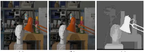
Researchers have given special attention to stereo vision as it is capable of acquiring disparity and hence the depth information of an observed scene. Many stereo vision techniques are using two adjacent forward-facing cameras, where each camera produces a 2D projection of the scene. Stereo vision techniques help in extracting 3D information using stereo pair taken by cameras. 3D information is very useful as it surmounts the problems and limits related to 2D. Stereo matching is a crucial step in stereo vision. For stereo matching, one image is taken as a reference image and the other as an input image. The pixels from reference image are matched with those of input image. Assuming the rectification is done, the horizontal distance between two matched pixels is termed as disparity. This disparity information is then translated into depth up to the scale factor. Fig. 1 shows one example stereo pair and ground truth of disparity map taken from Middlebury stereo vision page mentioned in Scharstein
et al. [1].
Stereo matching algorithms can be classified into feature based approach, window (area) based approach, and optimization based approach. In feature based methods,
Manuscript received November 24, 2013; revised January 24, 2014. The authors are with the Myongji University, Yongin, 449-728, Korea (e-mail: [email protected], [email protected], [email protected]).
various features were used. They are regions [2], [3], lines [4], [5], and points [6], [7]. For feature based matching, methods using spatial relations or invariant descriptors, relaxation method, and wavelets were proposed. In area based methods, no features are selected and regularly tessellated areas are usually used for matching. Area based matching methods can be categorized into three groups. They are cross correlation (CC)-like methods, Fourier transform-based methods, and mutual information methods. CC-like methods include normalized cross correlation (NCC), sum of squared difference (SSD), sum of absolute difference (SAD), and structural similarity (SSIM). Fourier transform-based methods include phase correlation and extended phase correlation [8]. Mutual information methods make use of joint and conditional entropy concepts. In optimization based methods, matching cost is computed and aggregated, and usually global optimization methods such as DP [9], energy minimization [10], and graph algorithms [11] are applied.
(a) (b) (c) Fig. 1. Stereo pair with ground truth (a). reference image, (b) input image,
and (c) ground truth.
Feature based approach generally produces sparse disparity map with high accuracy and low execution time. Window based approach generates dense disparity map with low accuracy and low execution time. Optimization based approach produces dense disparity map with high accuracy and high execution time. Since the ultimate goal of stereo matching is to obtain dense disparity map with high accuracy and low execution time, we choose to select optimization based approach and implement it in parallel framework to overcome execution speed deficiency. Among many optimization based methods, we select to exploit DP based on DSI since it seems most appropriate for implementing in parallel framework. In this paper, we propose a new parallel algorithm for DSI construction, DP, disparity computation, and disparity refinement using Compute Unified Device Architecture (CUDA) provided by NVIDIA. Unlike conventional parallel algorithms having only a single level of parallelism, we use two levels of parallelism.
This paper is organized as follows. Section II presents related work and Section III explains the proposed method. The experimental results are described in Section IV and Section V concludes the paper.
A New Parallel Implementation of DSI Based Disparity
Computation Using CUDA
II. RELATED WORK
In this section, several conventional DSI based stereo matching methods are reviewed.
Bobick et al. [12] proposed DSI based method in the presence of large occlusion. They used ground control points (GCPs) to reduce the sensitivity to occlusion cost and algorithmic complexity. GCPs are feature points that help in strong matching. GCPs are used to avoid smooth transient across depth discontinuities and allow disparity jumps that are needed at depth boundaries. They also made use of intensity edges since, in many cases, intensity edges and depth edges coincide. Their method produced reasonably good disparity results, but execution time is far from real time processing. Furthermore their method considers only ortho-frontal surfaces.
Tsai et al. [13] proposed a divide-and-conquer DSI approach that is a mixture of feature based method and optimization based method. Since feature based method alone is not able to generate dense disparity map, DSI based method is added. They first look for strong features and divide each row of the image into pieces and then conquer them using DSI based method. Thus strong features act the role of robust disparity guideline and DSI based method produces dense disparity map between features. Since strong features are used first, this method works well for low textured area also. However, due to feature finding and recursive nature of the method, execution requires too much time. For instance, it takes more than 20 minutes to process a stereo pair of 512 × 512 images.
Otha et al. [14] used DP for inter scan line search and intra scan line search for acquiring 3D information from stereo pair. Inter scan line matching was used for matching the connected edge, while intra scan line matching was for matching every edge given the connected edges. The algorithm successfully works for those images that contain the short connected edges, but for long connected edges, long processing time is required. Thus special type of hardware was used for segmenting the objects from images and this made the algorithm hardware dependent and costly.
Baha et al. [15] used DSI based DP method that was based on DSI construction and disparity map refinement. Window matching is performed for DSI construction. Shifting window of size 7×7 was used to avoid the recalculation of the sum of aggregate cost for each pixel in the window. This approach was efficient in terms of execution time but using window based approach may produce a lot of matching errors at disparity discontinuities.
Kim et al. [9] proposed DSI based method where they used adaptive search region to reduce the computation time for cost matrix calculation. Usually cost matrix is computed globally. However, they did full search only at the centerline, found matching path, and restricted search region for all other scan lines within 5 lines up and down of the previous scan line, thus reducing the computation time of cost matrix for DP. They used different neighborhood configuration when computing cost of each element in DSI. They also adopted regularization process in building the DSI where they took the average of DSI values of 1× 3 window to get final DSI value. Despite the effort of reducing the computation time, this method still takes too much time and is not suitable for real time applications.
For instance, it took almost 9 sec to process 512 × 512 stereo image pair.
Some researchers start to use graphics processing unit (GPU) with many cores to speed up the execution time for real time applications.
Gibson et al. [16] used GPU for the first time for the calculation of dense disparity map using semi global matching. Their proposed method is based on Birchfield et al.’s work [17]. Their method consists of cost computation, semi global matching for cost optimization, and disparity refinement. They are among the first who used GPU in stereo vision problem. Since GPU was adopted, there was a speedup in execution time. However, since the method was based on window matching, it did not produce satisfactory enough execution time that is crucial for real time applications.
Congote et al. [18] successfully implemented the algorithm in CUDA using GPU. The cost per pixel was calculated by aggregating the cost using SAD and optimal cost path is calculated using DP for each scan line in their proposed method. They used different GPUs for acquiring the running time of conventional parallel DP algorithm and showed that the GPU based algorithms exhibit lower execution time than CPU based algorithm and produce stable disparity maps. They tested five kinds of GPU boards with increasing number of cores and concluded that the more the cores are, the faster the performance is.
III. THE PROPOSED METHOD
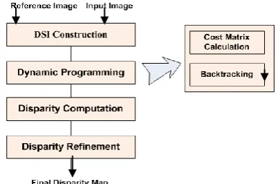
As was mentioned in Section I, we choose to use DP based optimization method utilizing DSI’s since it seems most appropriate for implementing in parallel framework. Fig. 2 shows the block diagram of the method we selected. DSI based DP method consists of four steps. They are DSI construction, DP, disparity computation, and disparity refinement. In the first step, DSI is constructed. In this paper, we assume that rectification is already done. Thus each corresponding row of reference image and an input image is used to construct DSI. For M × N image, N DSI’s of size M × M are constructed. Thus DSI space becomes M × M × N. In the second step, we perform DP consisting of two parts. In the first part, matching cost is aggregated to compute cost matrix. In the second part, backtracking is performed to designate the minimum cost path. The third step of the method computes disparities from each DSI and forms a whole disparity map. The final step refines disparities to remove possible disparity noise.
Following subsections describe parallel implementation algorithm for each step in Fig. 2.
A. DSI Construction
Concept: DSI represents the matching error between the row of reference image and the corresponding row of input image and can be obtained as in (1),
DSIn (xR, xI) = |IR (xR,n) - II (xI,n)| (1)
where IR (xR, n) is the pixel value of xR position of the nth scan
line in the reference image and II (xI, n) is that of the input
image. The process of making DSI for one scan line is shown in Fig. 3. Here a particular row indicated in white is used to construct DSI. We use the convention that one particular row from reference image is arranged horizontally from left to right and corresponding row from input image is arranged vertically from bottom to top to compute the absolute differences of corresponding element pairs. Thus lower left corner becomes the origin of DSI.
(a) (b)
Fig. 3. DSI of one scan line for stereo pair (a) stereo pair (b) constructed DSI.
Parallelization: Fig. 4 shows the parallelization of DSI construction step. Every corresponding row of reference image and input image is processed in parallel. Thus for, M x N image, N rows are processed simultaneously and this builds up one level of parallelism, termed as single parallelism (SPAR).
Recently CUDA invented a new way of parent child relationship in which one kernel function can be called from other kernel function. Using this functionality we develop one more level of parallelism. Within each row, matching cost, which is the absolute difference of corresponding pixel values in the reference and input images, is computed at the same time. This constitutes another level of parallelism, termed as double parallelism (DPAR). In CUDA implementation, parent kernel assigns N child kernels to N scan line pairs and each child kernel assigns M threads to M element pairs to compute the absolute difference at the same time.
Fig. 4. Computation of DSI in parallel.
B. Dynamic Programming
Concept: Dynamic programming helps in finding the
minimum cost path. The first stage of finding the minimum cost path is to calculate the cost matrix C. We compute the cost of matching error as in (2).
C(xR, xI) = min{C(xR-1, xI), C(xR-1, xI-1),
C(xR, xI-1)}+ DSI (xR, xI) (2)
where C(xR, xI) is the cost at location (xR, xI) and DSI (xR, xI)
is the DSI value at the same location. Three immediate previous neighbors of location (xR, xI) are considered to
compute the cost C(xR, xI) as depicted in Fig. 5. The neighbor with lowest cost is selected and is added to DSI value to get the final cost. Here we do not consider occlusion cost for the same reason described in Kim et al. [18]. They do not include occlusion cost to remove the effect of its heuristic nature. Along with the computation of cost matrix, direction information at every point describing where the lowest value comes from is also stored in direction matrix D for backtracking
(M,M)
(xR,xI)
(0,0)
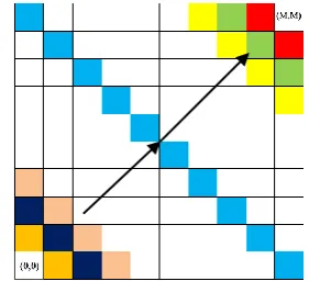
Fig. 5. Computation of cost matrix.
Parallelization: Fig. 6 shows the calculation of cost matrix in parallel. All elements on the same anti-diagonal (same colored elements) are processed simultaneously using one thread for each element. Direction of minimum neighbor is also saved simultaneously in D to be used later for backtracking. This is one level of parallelism and we termed it as SPAR.
Fig. 6. Parallel computation of cost matrix by following anti-diagonals.
To exploit the new functionality for DPAR in CUDA, we adopt to use parallel framework for DP proposed by Kiszkis
et al. [19]. They introduced the concept of DPAR to implement DP to find the most similar DNA among many kidney donors and donees. DPAR consists of inter-block parallelism and intra-block parallelism. Fig. 7 shows the division of DSI into multiple blocks to accommodate inter-block parallelism. Rhombus and triangle type blocks are defined and the blocks on the same diagonal can be processed in parallel. Fig. 8 shows the inside detail of each block. All the elements on the same diagonal can be processed at the same
DSI1
DSIK
time and this constitutes intra-block parallelism. In CUDA implementation, parent kernel assigns child kernel to each block and each child kernel assigns threads to elements in a block. The number of threads assigned is dependent upon the number of elements on the same diagonal and the shape of block. Rhombus type block will maintain the same number of threads for all of its diagonals, whereas triangle type block will have either increasing or decreasing number of threads depending on its topology.
Fig. 7. Block setup for inter-block parallelism.
Fig. 8. Intra-block parallelism.
C. Disparity Computation
Concept: Direction matrix D was saved along with the computation of cost matrix. Matching path is found by tracking back the saved direction from upper right corner to lower left corner of D. Fig 9 illustrates this step. The white line lying from upper right to lower left is called zero disparity line. Matching path is depicted in red. The vertical distance between the zero disparity line and matching path is the disparity of reference image. Similarly the horizontal distance between the zero disparity line and matching path is the disparity of input image
Parallelization: All the elements on zero disparity line are fed to parent kernel function which calls M child kernel functions. Every child kernel generates two threads, one for the horizontal distance calculation and other for the vertical distance calculation. Hence the DPAR is achieved. Computed disparities are sent to disparity refinement step to remove possible disparity noise.
Fig. 9. DSI image with matching path.
D. Disparity Refinement
Concept: After getting the initial disparity map in the previous step, disparity values are further refined. For this purpose, we use a 3 × 3 median filter.
Parallelization: M2 threads are generated and assigned to M × M elements to perform median filtering.
IV. EXPERIMENTAL RESULTS
The experiment is performed in a following environment. Test image pairs and corresponding ground truths are from Middlebury stereo vision page.
CPU : 3 GHz, Quad core, i5 RAM : 16G
GPU : NVIDIA GTX 780 with 2304 CUDA cores Parallel programming language : CUDA 5.5
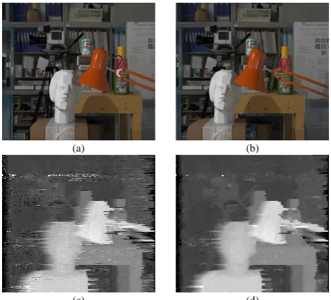
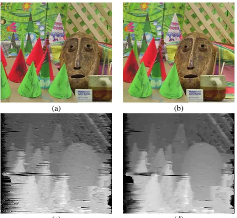
We run the proposed algorithm in two different scenarios: SPAR and DPAR. In SPAR, only one kernel is used with multiple threads, whereas, in DPAR, one parent kernel, multiple child kernels, and multiple threads are used. We also run non-parallel version of the proposed algorithm. Fig. 10 and Fig. 11 show the disparity results (with respect to reference image) of the proposed algorithm. The brighter the value is, the closer the object is to the camera. Fig. 10(a) and (b) are left and right images of Tsukuba pair respectively. Fig. 10(c) and (d) are disparity results for before refinement and after refinement respectively. As can be seen in both disparity results, disparities at depth boundaries are not crisp. This is due to the inherent limitation of DSI based approaches where disparities of neighboring locations cannot change abruptly. Other than this, light in the very front, human sculpture, desk, camera, and book shelves show reasonably good depth (disparity) appearances. Fig. 10(d), the refined version of Fig. 10(c), exhibits better results where disparity noise (especially on the book shelves) is almost completely removed. Fig. 11(a) and (b) are left and right images of Cone pair respectively. Fig. 11(c) and (d) are disparity results for before refinement and after refinement respectively. Similar observation can be made as in Fig. 10.
(a) (b)
(c) (d)
(a) (b)
(c) (d)
Fig. 11. Disparity results for Cone pair, (a) left image, (b) right image, (c) disparity before refinement, and (d) disparity after refinement.
Next we compare the execution speed of three versions of implementations: non-parallelism (NPAR), SPAR, and DPAR. Table I shows the execution time for each functional block of the algorithm and the total time. As was clearly expected, DPAR performs best and NPAR performs worst. Actual speedup is different for different parts of the algorithm. SPAR performs 2.5~10 times faster than NPAR, whereas DPAR performs 20~25 times faster than NPAR depending on the parts of the algorithm. Disparity refinement supports only SPAR, was the most time-consuming process, and governs the total execution time. Excluding disparity refinement, total times taken for NPAR, SPAR, and DPAR are 40, 11, and 1.9 µsecs respectively. Thus there are speedups of 4 and 20 times for SPAR and DPAR over NPAR respectively.
TABLE.I:EXECUTION TIME (µSEC) OF DIFFERENT APPROACHES.
DSI
construction DP
Disparity computation
Disparity refinement
Total Time Taken
NPAR 10 20 10 160 200
SPAR 2 8 1 35 46
DPAR 0.5 1 0.4 NA (35) 36.9
V. DISCUSSION
Stereo vision is a useful way of obtaining depth information where stereo matching is a necessary step. There are many approaches in stereo matching among which we select to use DSI based approach since it seems most suitable for parallel implementation. We proposed the algorithm that consists of four steps. They are DSI construction, DP, disparity computation, and disparity refinement. We suggested the concept of SPAR and DPAR of CUDA for the first three steps. However the fourth step could only be implemented in SPAR. We generated the disparity results that are reasonably good and showed that the disparity after refinement is better than the one before refinement. We also compared the execution time of three scenarios depending on the level of parallelism and confirmed that DPAR performed best.
Though the proposed method showed reasonably good results in terms of execution time, disparities at depth boundaries are still fuzzy. In execution time, disparity refinement, doing only median filtering, governs the total execution time. We may need some other speedy way of disparity refinement. Improvement on these is intended for future research.
ACKNOWLEDGMENT
This work (Grants No. C0005448) was supported by Business for Cooperative R&D between Industry, Academy, and Research Institute funded by Korea Small and Medium Business Administration in 2012.
REFERENCES
[1] D. Scharstein and R. Szeliski, "A taxonomy and evaluation of dense two-frame stereo correspondence algorithms," International Journal of Computer Vision, vol. 47, pp. 7-42, 2002.
[2] J. Flusser and T. Suk, “A moment-based approach to registration of images with affine geometric distortion,” IEEE Transactions on Geoscience and Remote Sensing, vol. 32, pp. 382–387, Mar 1994. [3] M. Roux, “Automatic registration of SPOT images and digitized
maps,” in Proc. the IEEE International Conference on Image Processing, Lausanne, Switzerland 1996, vol. 2, pp. 625–628. [4] J. Canny, “A computational approach to edge detection,” IEEE
Transactions on Pattern Analysis and Machine Intelligence, vol. 8, pp. 679–698, Nov 1986.
[5] D. Shin, J. K. Pollard, and J. P. Muller, “Accurate geometric correction of ATSR images,” IEEE Transactions on Geoscience and Remote Sensing, vol. 35, pp. 997–1006, Jul 1997.
[6] S. Banerjee, D. P. Mukherjee, and D. D. Majumdar, “Point landmarks for registration of CT and NMR images,” Pattern Recognition Letters, vol. 16, pp. 1033–1042, 1995.
[7] Q. Zheng and R. Chellapa, “A computational vision approach to image registration,” IEEE Transactions on Image Processing, vol. 2, pp. 311–325, July 1993.
[8] E. D. Castro and C. Morandi, “Registration of translated and rotated images using finite Fourier transform,” IEEE Transactions on Pattern Analysis and Machine Intelligence, vol. 9, pp. 700-703, Sept 1987. [9] C. H. Kim, H. K. Lee, and Y. H. Ha, “Disparity space image based
stereo matching using optimal path searching,” Image and Video Communications and Processing, vol. 5022, pp. 752-760, 2003. [10] J. Sun, Y. Li, S. B. Kang, and H. Y. Shum, “Symmetric stereo
matching for occlusion handling,” in Proc. IEEE Computer Society Conference on Computer Vision and Pattern Recognition, 2005, vol. 2, pp. 399–406.
[11] O. Veksler, “Extracting dense features for visual correspondence with graph cuts,” in Proc. IEEE Computer Society Conference on Computer Vision and Pattern Recognition, 2003, vol. 1, pp. 689–694. [12] A. F. Bobick, “Large occlusion stereo,” Int’l J. Computer Vision, vol.
33, no. 3, pp. 181-200, 1999.
[13] C. J. Tsai and A. K. Katsaggelos, "Dense disparity estimation with a divide-and-conquer disparity space image technique," IEEE Trans. Multimedia, vol. 1, pp. 18-29, Mar. 1999.
[14] Y. Ohta and T. Kanade, “Stereo by intra- and inter- scanline search using dynamic programming,” IEEE Trans. Pattern Anal. Machine Intelligence, vol. 7, Mar. 1985.
[15] N. Baha and S. Larabi, “Real-time disparity map computation based on disparity space image,” in Proc. The 13th International Arab Conference on Information Technology, 2012, pp. 10-13.
[16] J. Gibson and O. Marques, "Stereo depth with a unified architecture GPU,” in Proc. IEEE Computer Society Conference on Computer Vision and Pattern Recognition Workshops, June 2008, pp. 1–6. [17] S. Birchfield and C. Tomasi, “A pixel dissimilarity measure that is
insensitive to image sampling,” IEEE Transactions on Pattern Analysis and Machine Intellignce, vol. 20, no. 4, 1998.
[18] J. E. Congote, J. Barandiaran, I. Barandiaran, and O. Ruiz, "Realtime dense stereo matching with dynamic programming in CUDA," in Proc. Donostia-San Sebastian, Spain, Sept. 2009, pp. 9-11.
Aamer Mehmood was born in Kasur, Pakistan on May 1, 1988. He got BS in electrical engineering in 2011 from Govt. College University in Lahore, Pakistan. He entered a master course in information and communication engineering in Myongji University in 2012.
His current interest of research includes object extraction, stereo vision and parallel algorithms for image processing.
Youngsung Soh was born in Seoul, Korea on Mar. 4,
1956. He got BS in electrical engineering in 1978 from Seoul National University in Seoul, Korea. He obtained MS and PhD in computer science from the University of South Carolina in Columbia, South Carolina, USA in 1986 and 1989, respectively.
He served in the Korean army from June 1980 to Sept. 1982. He worked in Systems Engineering Research Institute in Korea as a senior researcher from Sept. 1989 to Feb. 1991. He joined Myongji University in Korea from Mar. 1991 and is currently a full professor in the Dept. of Information and Communication Engineering.
His current interest of research includes object tracking, stereo vision, and parallel algorithms for image processing.
Prof. Soh is a member of Korea Information Processing Society and Korea Signal Processing Systems Society.
Intaek Kim was born in Seoul, Korea in 1960. He
received BS and MS in electronics engineering from Seoul National University in Seoul, Korea in 1980 and 1984 respectively. He obtained PhD in electrical engineering from Georgia Institute of Technology in Atlanta, Georgia, USA in 1992.
He worked for Goldstar central research lab from 1993 to 1995 as a senior engineer and joined Myongji University from 1995. He is now a professor in the Dept. of Information and Communication Engineering. His recent publications deal with the area of face recognition, hypersepctral image and MR imaging.
His research interest includes pattern recognition, image processing and smart grid area.