Themed Section : Engineering and Technology © 2018 IJSRSET | Volume 5 | Issue 3 | Print ISSN: 2395-1990 | Online ISSN : 2394-4099
Performance of Rectangular Microstrip Patch Antenna in Two
Different Design Tools - A Comparative Study
E. Aravindraj1, A. Kannan2, Dr. K. Ayyappan3,123Department of ECE, Rajiv Gandhi College of Engg& Tech, Puducherry, India
[email protected], [email protected]2, [email protected]3
ABSTRACT
In this comparative study, Two antenna designing tools where compared each other to get appropriate output for the calculated design parameters. Here, there are four different rectangular microstrip patch antennas (RMPA) has been designed for four different frequencies like 2.4 GHz, 3.5 GHz, 5.2 GHz and 5.8 GHz separately using two different antenna design tools like Advanced design software (ADS) and High Frequency simulator software (HFSS). Flame Retardant (FR4) is used as the dielectric material with microstrip feed to the rectangular patch. The comparison is based on the variations obtained in the design parameters like length, width and height and their respective simulation parameters. Hence, by comparing the design parameters and simulation parameters obtained for the operating frequencies with both the tool, it has been concluded that which tools can work efficiently with accuracy. Thus, this paper provides t a clear opinion about which tool is suitable for getting appropriate simulation results for the corresponding calculated design values.
Keywords— Rectangular Microstrip patch antenna (RMPA), FR-4 substrate, Ground Plane, Microstrip feed, ADS and HFSS.
I.
INTRODUCTIONRectangular Microstrip Patch Antenna is a smaller in size, less in cost, lighter in weight. It can be integrated with many types of feeds. But, it has major limitations like low gain, less efficient, narrow bandwidth, etc [1]. MPA has become very widespread in mobile applications. It is increasingly more useful because it can be printed in the circuit board itself. It is also used in several wireless applications [2]. Permittivity of dielectric and its thickness will regulate the MPA. Thick substrates with less dielectric constant are used to increase the bandwidth and antenna efficiency, but the element size will be larger which difficult during portability. FR-4 is a composite material with low cost, high mechanical strength, reliability and convenient availability [3] [4]. It provides an actual value for
high frequency. Here, there are four different ISM band frequencies such as 2.4 GHz, 3.5 GHz, 5.2 GHz and 5.8 GHz are taken under account. The design parameters are calculated using pre-defined antenna design formulae and with the same design parameters antennas have been designed by two popular design software. Hence, from the calculated design values the RMPA are designed with slight changes made in the dimensions to get appropriate output for the corresponding frequency have obtained for the antenna design [5].
taken for comparison. Advanced Design System (ADS) is used in designing RF electronic, microwave Simulations and in digital applications with high speed. MPA are used widely because of its robustness and compact to environment.
This antenna design will provide a preferable impedance matching through microstrip feeding technique between the patch and the transmission line. It provides an extensive set of projects to demonstrate in designing various projects. It also provides platform for design the circuit and the antenna design. ADS has a affordable features such as maintaining a single source of design and reducing disk space by sharing designs [6].
High frequency simulator software (HFSS) has more advancement in 3D EM software used in designing antenna and complex RF electronic circuits. This level of analysis can give design sensitivity, performance and market with confidence in results [7]. It provides good designing properties in three-dimensional structure. Some key features for HFSS are designing and analysing the element, integrated on design with automated process with a linear circuits design.
II.
ANTENNA DESIGN PARAMETERSThe operational antenna is made using the measurements obtained using the pre-defined antenna design formulae equations for calculating the by the patch, substrate and ground plane. The optimized design consists of a 0.04mm thicker microstrip patch and ground plane with substrate element placed in centre of the ground plane and the patchwhich has a thickness of 1.6mm denotes the geometric size of the antennas. Thus, these all combined together to make an efficient antenna
design [8] [9]. The calculated size of the antenna varies while applying it into a structural design. Since, there will be an optimal value for the structural design which provides good output parameters for the design. Hereby, the design and geometry of the system has been explained below
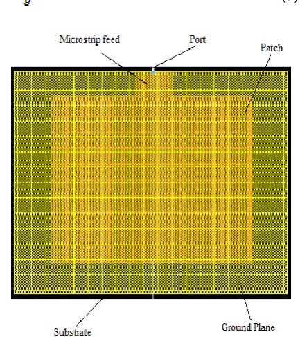
A. Rectangular Microstrip Patch
The proposed design is a RMPA designed using ADS and HFSS tools as shown in Fig. 1 and Fig. 2. These rectangular patches have different dimensions according to the radiating frequency to which it is designed for. The mathematical value of 2.4 GHz operating frequency is 30x38x0.04mm for 2.4 GHz. In ADS tool, it is optimized as 33x45x0.04mm. In HFSS tool, it is 30x38x0.04mm. The simulations are made for the designed antennas using ADS and HFSS software. Thus, the difference in the antenna design parameters and the output parameters are compared.
B. Substrate and Ground Plane
FR-4 is an electrical insulator with dielectric constant ( ). Compared to other type of substrates FR-4 provides good parametric outputs. The characteristics of the FR-4 substrate provide a good mechanical strength and reliability [11]. FR-4 is used in the PCB boards, relays and switches. The height of the FR-4 substrate is considered as 1.6 mm. The height and the dielectric constant desire the geometric size of the antenna. The calculation of antenna design for the operating frequency (fr=2.4 GHz, 3.5 GHz, 5.2 GHz and 5.8 GHz) is explained as follows [10] [11].
Patch Width (W): W = (1)
Effective Dielectric Constant ( ):
= (2)
Patch Length Extension (ΔL):
ΔL=0.412h (3)
Effective Patch Length (Leff):
= (4)
Patch Length (L):
L = (5)
Substrate Width Ground plane width :
(6)
Ground Plane length ( Substrate length ( :
(7)
Figure 1. Design of Rectangular Microstrip Patch Antenna Using ADS Software
Figure 2. Design of Rectangular microstrip patch antenna using HFSS software
III.
SIMULATION PARAMETERS AND RESULTSThe optimization antenna designs are simulated using ADS and HFSS software which provides a good platform for presenting the work effectively. The simulated antenna parameter shows that the antenna perfectly radiates at the ISM band of frequencies such as 2.4 GHz, 3.5 GHz, 5.2 GHz and 5.8 GHz [12]. But, the calculated values and optimization value slightly vary for the software design.
A. Simulation Parameters
The Return loss and the Bandwidth Performances of the antenna designs are compared below. Here, the outputs of different frequencies like 2.4 GHz, 3.5 GHz, 5.2 GHz and 5.8 GHz with different tools like ADS and HFSS have been elaborated.
1) Return Loss
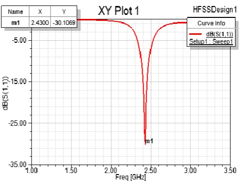
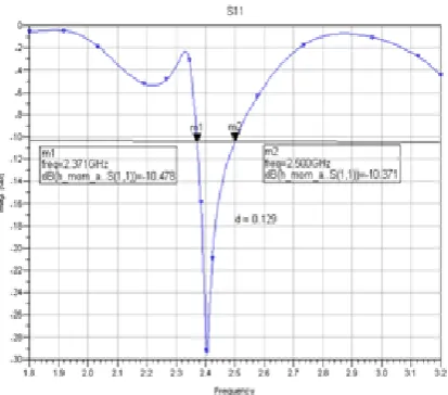
The return loss is the loss of power due to the reflection of radiated signal from the obstacle which also affects the other signals radiated by the antenna. The Fig. 3a, 4a, 5a and 6a denotes the return loss value achieved by the ADS software. The Fig. 3b, 4b, 5b and 6b represents the return loss value of the designed antennas obtained the simulation made in HFSS software.
Figure 3(a). Return loss for 2.4 GHz using ADS
The value of return loss in the antenna design for 2.4 GHz using ADS software is -28.347 dB as in fig. 3a. And using HFSS Software is -30.16 as in Fig. 3b.
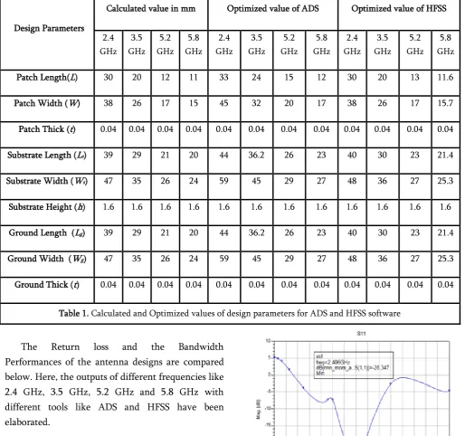
Design Parameters
Calculated value in mm Optimized value of ADS Optimized value of HFSS
2.4 GHz
3.5 GHz
5.2 GHz
5.8 GHz
2.4 GHz
3.5 GHz
5.2 GHz
5.8 GHz
2.4 GHz
3.5 GHz
5.2 GHz
5.8 GHz
Patch Length(L) 30 20 12 11 33 24 15 12 30 20 13 11.6
Patch Width (W) 38 26 17 15 45 32 20 17 38 26 17 15.7
Patch Thick (t) 0.04 0.04 0.04 0.04 0.04 0.04 0.04 0.04 0.04 0.04 0.04 0.04
Substrate Length (Ls) 39 29 21 20 44 36.2 26 23 40 30 23 21.4
Substrate Width (Ws) 47 35 26 24 59 45 29 27 48 36 27 25.3
Substrate Height (h) 1.6 1.6 1.6 1.6 1.6 1.6 1.6 1.6 1.6 1.6 1.6 1.6
Ground Length (Lg) 39 29 21 20 44 36.2 26 23 40 30 23 21.4
Ground Width (Wg) 47 35 26 24 59 45 29 27 48 36 27 25.3
Ground Thick (t) 0.04 0.04 0.04 0.04 0.04 0.04 0.04 0.04 0.04 0.04 0.04 0.04
Figure 3(b). Return loss for 2.4 GHz using HFSS
Figure 4(a). Return loss for 3.5 GHz using ADS
Figure 4(b). Return loss for 3.5 GHz using HFSS
The return loss for the operating frequency 3.5 GHz in ADS and HFSS software are shown in the Fig.4a and b respectively. Since, the return loss value in ADS and HFSS tool is -33.679dB and -34.66dB.
Figure 5(a). Return loss for 5.2 GHz using ADS
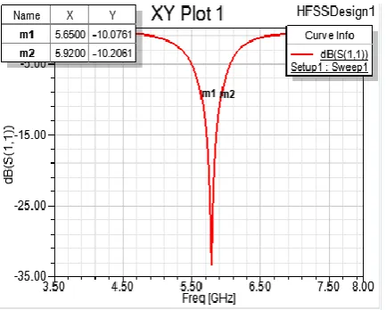
Figure 5(b).Return loss for 5.2 GHz using HFSS
Figure 6(a).Return loss for 5.8 GHz using ADS
Figure 6(b).Return loss for 5.8 GHz using HFSS
The return loss value of the RMPA design using HFSS software is -33.30dB for 5.8 GHz and -34.34 dBusing ADS.
2) Bandwidth
Bandwidth is the frequency range where the designed antenna radiates properly. The fig. 7a, 8a, 9a, 10a, 11a and fig. 7b, 8b, 9b, 10b, 11b shows the bandwidth range of the antenna design made by ADS and HFSS software respectively.
Figure 7(a). Bandwidth for 2.4 GHz using ADS
Figure 7(b). Bandwidth for 2.4 GHz using HFSS
The Bandwidth value obtained for 2.4 GHz operating frequency using HFSS Software is 90 MHz as in fig. 7b.The Bandwidth value of the antenna design for 2.4 GHz using ADS software is 130 MHz as in fig 7a.
Figure 8(a).Bandwidthfor 3.5 GHz using ADS
Figure 8(b).Bandwidthfor 3.5 GHz using HFSS
Figure 9(a).Bandwidthfor 5.2 GHz using ADS
Figure 9(b).Bandwidth for 5.2 GHz using HFSS
Figure 10(a).Bandwidthfor 5.8 GHz using ADS
As shown in Fig. 9a and b, Bandwidth value for 5.2 GHz operating frequency in ADS and HFSS tool is 260 MHz and 120 MHz respectively.The Bandwidth value of the RMPA design using ADS and HFSS software is 245 MHz and 170 MHz for 5.8 GHz as in fig. 10a and 10b.
B. Simulation Results
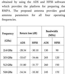
The antenna simulation parameters explained above are tabulated in Table II. The simulation results are obtained by using the ADS and HFSS software which provides the platform for preparing the RMPA. The proposed antenna provides good antenna parameters for all four operating frequencies.
Table II. Simulation output obtained by ADS and HFSS software
IV.
CONCLUSIONA RMPA designed for the given operation frequencies provides a good simulation parameter in both the software. The Advanced design software (ADS) and High frequency simulator software (HFSS) gives a good platform to design an antenna structure. Here, HFSS provides the output
with the design parameters which are obtained from the design formula. Since, the calculated and the optimized value of the antenna design is nearly the same. But the ADS tool needs some changes in the design parameters of the antenna which varies from the calculated values. Thus, this paper concludes that the both the tools provides an efficient simulation parameters but taking design parameter under account HFSS tool provides accurate design for an operating frequency.
V.
REFERENCES[1] A. S. U. Constantine and A. Balanis, “Antenna Theory: Analysis and Design”, 3rd ed: John Wiley& Sons, Inc, pp. 811-882.
[2] T. Jayachitra, V.K Pandey and Anshuman Singh, “Design of Microstrip Patch Antenna for WLAN Applications,” International Journal of Advanced Research in Electrical, Electronics and Instrumentation Engineering, Vol. 3, Special Issue 3, April 2014.
[3] A. A. Qureshi, M. U. Afzal, T. Taqueer and M. A. Tarar, “Performance Analysis of FR-4 Substrate for High Frequency Microstrip Antennas”, China-Japan Joint Microwave Conference, Vol. 5, May 2011.
[4] Kiran Jain and Keshav Gupta, “Different Substrates Use in Microstrip Patch Antenna-A Survey”, International Journal of Science and Research, ISSN 2319-7064, May 2014.
[5] Pradeep Kumar, Neha Thakur and Aman Sanghi, “Micro strip Patch Antenna for 2.4 GHz Wireless Applications”, International
Journal of Engineering Trends and
Technology, Vol. 4, Issue 8, August 2013.
Frequency
(GHz)
Return loss (dB) Bandwidth
(MHz)
ADS HFSS ADS HFSS
2.4 GHz -28.34 -30.10 130 90
3.5 GHz -33.67 -34.66 265 120
5.2 GHz -31.80 -31.77 260 150
[6] E. Aravindraj and Dr. K. Ayyappan, “Design of slotted H-shaped patch antenna with dumbbell shaped DGS for 3.5 GHz WiMAX applications”, Indian Journal of Innovations and Developments, Vol. 5, no. 2, February 2016.
[7] Ogunlade Michael Adegoke, Ismael Saad Eltoum, “Analysis and Design of Rectangular Microstrip Patch Antenna AT 2.4Ghz WLAN Applications”,
International Journal of Engineering Research & Technology (IJERT), Vol. 3 Issue 8, August – 2014.
[8] Muhammad AamirAfridi, “Microstrip Patch
Antenna − Designing at 2.4 GHz Frequency”,
Biological and Chemical Research, March 2015.
[9] Pradeep Kumar Sharma, RiteshSaraswat and JitendraJangir, “Performance Analysis of Square Shaped Microstrip Patch Antenna For S Band Application”, International Journal of Modern Trends in Engineering and Research, Vol. 03, Issue 10, October 2016.
[10] Ramesh Garg and PrakashBhartia, InderBahl, “Microstrip Antenna Design Handbook”, Second Edition, 1998.
[11] Vikram Thakur and SanjeevKashyap, “A Review
Paper on Techniques and Design for Microstrip Patch Antenna”, International Journal of Advanced Research in Electrical, Electronics and Instrumentation Engineering, Vol. 4, Issue 2, February 2015.
[12] E. Aravindraj and Dr. K. Ayyappan, “ Survey on slotted H-shaped MPA design for different ISM band radio frequencies,”Indian Journal of Innovations and Developments, Vol. 5, no.3, March, 2016.
[13] HashibulAlam, “Design of rectangular microstrip
patch antenna for IEEE 802.1503a (WPAN) with MB_OFDM ultra wide band communication system”,International Journal of Scientific and Research Publications, Vol. 4, Issue 2, February 2014.