A Meta-model Based Modeling Method for
Geographic Information Model in CTCS
Hardware-in-the-loop Simulation System
Linyan TU
Tsinghua National Laboratory for Information Science and Technology Department of Automation, Tsinghua University, Beijing 100084, China
E-mail:[email protected]/[email protected]
Wei DONG, IEEE Member, Yindong JI, IEEE Member, Xinya SUN Tsinghua National Laboratory for Information Science and Technology Department of Automation, Tsinghua University, Beijing 100084, China E-mail:[email protected], [email protected], [email protected]
Abstract—According to the requirement of hardware-in-the-loop simulation system for CTCS Level 3 (Chinese Train Control System Level 3), a meta-model based modeling method for railway geographic information is proposed in this paper. The modeling principle, modeling scheme and key technologies of this method are deeply explained and different modeling schemes are compared in detail. Using this modeling method, the railway geographic information can be expressed more concisely and completely, and the model can be extended and reconstructed more easily. The proposed model is now successfully used to provide effective support for the running of the train dynamic model.
Index Terms—Chinese Train Control System, hardware-in-the-loop simulation system, meta-model, railway geographic information model
I. INTRODUCTION
Nowadays, Chinese railway transportation is in rapid development. The aim of the under developing Chinese Train Control System Level 3 (in short, CTCS level 3) is to provide high-speed train control support for high-speed railway, especially for the Passenger Dedicated Line, whose speed will reach 350Km per hour. Since the speed is so high, the key point of the Passenger Dedicated Line is safety, which requires the train control system to be extremely reliable. Therefore , the train control equipments and the whole train control system need to be tested and verified thoroughly before use.
However, testing the train control equipments in real railway lines is expensive, inefficient and dangerous for obvious reasons. In this case, an effective hardware-in-the-loop simulation system is in great need, because:
1) the system can provide effective testing and verifying environment for developing, manufacturing and integrating of concerned equipments;
2) the system can be helpful not only to further promoting fundamental research and technical innovation of railway communication and signaling domain, but also to further boosting safety class and operation efficiency of high-speed railway train control system;
3) the system is very helpful for realizing system-level test and verification, which is very important because it can find system-level faults and integrating errors that cannot be found by conventional equipment-level test.
In order to build complete line-level railway simulation environment, the CTCS level 3 hardware-in-the-loop simulation system is required to completely reproduce the function structure of the railway line and train control system in different levels. Particularly, a geographic information model should be built first.
Geographic information model is an effective emulation of real railway line on the aspect of information and logic. Without geographic information model, the train dynamics model and on-board equipment models will have no running environment. Thus it is an important part of the simulation system. Since it plays a vital supporting role in the whole simulation system, it should concisely and effectively reproduce the fundamental function and key characteristics of the real railway line.
Since the quality of the geographic information model will directly influence the basic structure, operation efficiency and simulation fidelity of the system, this paper will focus on how to construct a high-quality geographic information model that is suitable to the CTCS Level 3 hardware-in-the-loop simulation platform.
II. CURRENT RESEARCH SITUATION
working principle of on-board BTM as it passes the trackside balise at high speed and proposed a real-time hardware-in-the-loop simulation system for testing and evaluating the major performance of BTM [1] . The testing was executed for the equipment of BTM; in Reference [2], the structure of test platform was described and the core function of CTCS level 3 on-board equipments was given. However, these tests are just for on-board equipments [2], not for system level.
Among all the description systems of railway geographic information, the most frequently used is the Railway Geographic Information System (RGIS). Usually, "RGIS is an application technology system, based on Geographic Information System (GIS) and computer network, served for plan, management, decision and application of the railway system" [3].
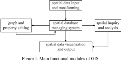
According to the definition of RGIS, GIS is the core and key to RGIS. GIS is a geographic spatial model composed of computer software program and geographic information data. Main functional modules of GIS software system are shown in figure 1 [4].
Figure 1. Main functional modules of GIS
From Fig. 1, it is known that the main function of GIS is to organize, manage, analyze and display the spatial data which is to indicate many aspects of information about the entity, such as position, shape, size and distribution characteristics, and so on. The geographic information model mentioned in this paper is the carrier for the running of train model in the simulation platform, so the basic information and key characteristic of real railway line (which contains not only common spatial data but also plenty of line property data and line connection information) should be concisely and effectively described. If these data is all managed by GIS, many functions are extremely complicated to achieve [5]. In this sense, GIS is not an ideal choice. The geographic information model should be established to adapt to the specific requirement of the CTCS level 3 hardware-in-the-loop simulation system. In addition, even if GIS is used in secondary development, it is also necessary to further study and build model aimed at railway line based on general spatial data model. Hence, the related modeling method can still be used.
III. MODELING TARGET AND PRINCIPLE
The major function of geographic information model is to offer real-time line parameters and equipment information of railway line according to the coordinate of train position, so as to provide necessary information to
make train dynamics model and on-board equipment model maintain normal running.
Railway line parameters mainly contains: length, gradient, radian, speed limit, delimitation, axis weight limit, topographical features, weather conditions, distribution of buildings such as railway stations, bridges, tunnels, culverts and landscapes, and so on. Trackside equipment distribution information means the distribution position of the equipments along railway. These equipments include balise, track circuit, Landside Electronic Unit(LEU), point switches, signal controllers, interlocking, Centralized Traffic Control(CTC), Radio Block Center(RBC), Train Control Centre(TCC), GSM-R wireless base station. Thus, geographic information model should express information as follows: topological structure of the whole line, railway line parameters and equipment distribution along the line.
Generally speaking, a good model should be as simple, complete, accurate, and expandable as possible, which is the target of the geographic information modeling. Simplicity means model should be as simple as possible on condition that the function requirement is satisfied. Completeness means model should completely express the related information of the modeled object. Accuracy means model should accurately present the key characteristics of the modeled object. Expansibility means model should be convenient to adjust and extend so as to adapt to the change of the modeling requirement. In order to achieve these targets, the following modeling strategy should be adopted: first, the structure of the model and the structure of the modeled object should be identical; second, information presented by model should be complete and non-redundant. The modeling technology based on meta-model is well fit for these modeling demands.
Meta-model is the model about model itself and capable to represent basic information component of modeling information. Meta-model is more abstract than model, and it could better realize the integration of the model [6][7][8]. Therefore it could be well capable to express systemic model [6][7]. Adopting meta-modeling technology, it is possible to make the structure of established model clearly, easy to express and well expandable. Using meta-modeling method, the crucial problems that need to be considered are how to define the meta-models, and how to express the application model appropriately and naturally through integrating the meta-models.
IV. MODELING SCHEME
A. Establishment of Coordinate System
association between the position coordinates, and the degree of freedom is too high. As trains always running along the railway line (the degree of freedom is one), three-dimensional coordinate is not the best choice. Instead, curvilinear coordinate system similar to the parametric equation curve is needed [9]. In this curvilinear coordinate system, One-dimensional coordinate can express three-dimensional coordinate information.
In order to establish coordinate system of the geographical information model, the entire railway network is divided into a number of curves with no bifurcation. That kind of curve is called “basic line”, and each basic line has unique identification (ID). The position and shape of a basic line can be described by interpolation points: Suppose A1, A2, A3… are points in the three-dimensional coordinate system, connecting the point sequence A1, A2, A3…smoothly can make a smooth space curve in that coordinate system. Hereby, A1, A2, A3…… are the interpolation coordinate points.
One-dimensional coordinate system in each basic line can be established as follows: select the start point S and the end point E of the basic line
α
; for any given point P onα
, measure the distance from point S to point P along curveα
, and take that distance x as the unique one-dimensional curvilinear coordinate of P; reversely, given a real numberx
(0 ≤x
≤ L, L is the length of basic line), through similar way, a unique point P can be determined byx
. In this way, one-dimensional curvilinear coordinate system based on basic lineα
is established.After the two steps above, a one-dimensional curvilinear coordinate system cluster based on basic lines has been established globally:
{
α
i|
i
K
}
Θ =
∈
(4.1)Here,
Θ
means the coordinate system cluster, αi means one basic-line coordinate system, K means index set (or marking set).Based on the coordinate system cluster
Θ
, a unique position on the railway line can be determined by coordinate( , )
i x
globally. Here,i
represents the ID of basic line, which is used to determine a basic-line coordinate systemα
i inΘ
;x
represents a one-dimensional curvilinear coordinate onα
i.To sum up, the coordinate system of geographical information model can be expressed in triples as follows:
( , , )
ξ
Γ =
Λ Θ
(4.2)where
ξ
represents the basic coordinate system, such as three-dimensional rectangular coordinate system or three-dimensional earth coordinate system;Λ
represents the method of dividing the entire railway network into a number of basic lines; Θ represents the basic-line coordinate system cluster based onξ
andΛ
. Therefore,the dividing and modeling method of basic line is the key of establishing the geographical information model.
B. The Expression of Topologic Information
Since the entire railway network has been divided into a cluster of basic lines, the topologic information of railway network is virtually to describe the connection relation between these basic lines. The connection relation of basic lines can be expressed by cross points of the basic lines: two basic lines
l
1andl
2 intersects atpoint
P
i, the coordinates ofP
i onl
1andl
2are( , )
i x
1 1and
( ,
i x
2 2)
. Therefore, pointP
i can be expressed asfollows:
1 1 2 2
[( , ), ( ,
)]
iP
=
i x
i x
(4.3)Thus,
p
ican express connection relation between two basic lines, and the topologic information of the whole system can be expressed as a set of all such cross points in the system:{ |
P i U
i}
Ψ =
∈
(4.4)Ψ
Represents the set of all cross points of basic lines,i
P
represents one cross point of two basic lines, U is index set.In the simplest case, basic lines intersect at start point or end point. This case is also the modeling method which this paper desired to use. In this case, the connection relation of the basic lines can be expressed as follows: the basic line connected with the start point S of
i
l
is named “previous basic line” ofl
i, and the basic lineconnected with the end point E of
l
i is named “next basicline” of
l
i; if the connection relation ofl
i with otherbasic lines is marked as
I
i, then the connection relation of a basic line as well as the whole topology can be expressed as follows:{(
,
) |
,
)}
{ |
}
i pre next pre next
i
I
l
l
l
l
L
I i W
=
∈
Ω =
∈
(4.5)Hereby,
I
irepresents the connection relation of basicline
l
i; L represents the basic line set;l
prerepresents theprevious basic line object of
l
i;l
next represents the nextbasic line object of
l
i.(
l
pre,
l
next)
can uniquely identifythe back and forth connection relation of the basic line
l
i. The set Ω of all such connection relations can describe the topology of the whole system.However,
I
i just expresses which basic line isconnected to the basic line
l
i’s start point or end point,connected to
l
i . The solution is as follows: if theconnected point is the start point S of
l
pre orl
next, it isdefined as positive connection; while the connected point is the end point E of
l
pre orl
next, it is defined as negativeconnection.
Therefore, after modifying the equation 4.5, we get the complete connection relation of basic
lines:
{[(
,
), (
,
) |
,
)}
i pre pre next next pre next
I
=
l
dir
l
dir
l
l
∈
L
(4.6)Here,
dir
is a Boolean value;(
l
pre,
dir
pre)
represents the previous basic line ofl
i isl
pre, and the connectedpoint is the start point of
l
pre (whendir
pre is true), orthe end point of
l
pre (whendir
pre is false); the meaningof
(
l
next,
dir
next)
is similar to(
l
pre,
dir
pre)
.C. The Expression of Line Parameters and Equipment Information
Equipment information just means the distribution of the equipment position, not the equipment object itself. Hence, the expression way of equipment information is similar to the line parameters, so we uniformly regard the line parameters and equipment information as “general equipment” (called them “equipment” for short). The equipments are classified into point equipments (the location is determined by a point) and interval equipments (the location is determined by an interval). Point equipment information can be expressed by
( , )
i l
, and interval equipment information can be expressed by1 2
( , , )
i l l
. Here,i
means the ID of equipment;l
means the location of point equipment;l l
1,
2means the position of the start and end point of the interval equipment, and they are both one-dimensional curvilinear coordinates on basic line.From the analysis above, basic line can be used as the minimum cell of the geographical information model, so as to be taken as the carrier of equipment information and line parameters. In software implementation, line parameters and equipment information exist as attribute of the basic line object, and they are organized in the form of linked list. The node content of the linked list is
( , )
i l
or( , , )
i l l
1 2 , ranking by position sequence. In this way, the line parameters and equipment information can be expressed in actual relation of position. To unify the expression of node content of the linked list,( , )
i l
can beexpressed as
( ,
i l
− Δ + Δ
l l
,
l
)
.Therefore, basic line can be used as the meta-model of the geographic information model. Thus, how to divide basic lines is the key point of modeling.
D..Virtual Line and Coordinate Transformation
If the equipment has a large scale, the equipment will belong to multiple basic lines. In this case, if only take
one of the basic lines as the carrier of the equipment information, the equipment information of other basic lines will not be complete; if take all the basic lines as the carriers, the equipment information will be redundant. To solve this problem, the concept of virtual line is brought in.
The main attention point for modeling the virtual line is the overall direction of railway line. Taking BeiJing-TianJin railway line as an example, virtual line may be modeled into a curve along the railway line from BeiJing to TianJin (for example, the middle axial line of the railway line can be taken as the curve). Using a similar method as the establishment of basic-line coordinate system cluster, the virtual-line coordinate system cluster
'
Θ
can be established.( , )
j x
is used to represent the coordinate of a point on virtual line. Hereby,j
represents the virtual line ID,
x
represent the one-dimensional curvilinear coordinate on virtual line.Generally, one virtual line corresponds to a number of basic lines, but one basic line only corresponds to one virtual line. For any point
( , )
i x
1 in the basic-linecoordinate system cluster
Θ
, there is a unique corresponding point( ,
j x
2)
in virtual-line coordinatesystem cluster
Θ
'; but there may be more than one point on basic lines corresponding to one point on virtual line.The mapping from basic-line coordinate system to virtual-line coordinate system can be fulfilled in the form of interpolation points. For any point
( , )
i x
in basic linei
, if the virtual-line mapping points of basic-line points( , )
i x
1 and( ,
i x
2)
are known as( ,
j y
1)
and2
( ,
j y
)
, the virtual-line mapping point( , )
j y
of thebasic-line point
( , )
i x
can be calculated by the following formula:2 1
1 1
2 1
(
)
y
y
y
y
x
x
x
x
−
=
+
−
−
(4.7)Hence, the coordinate mapping from basic line
i
to virtual linej
can be expressed by a series of coordinates of interpolations points:1 1 2 2
( ,
x y
), ( ,
x y
),
"
(
x y
k,
k)
(4.8)Querying the distribution information of large-span equipment at the point
( , )
i x
on basic line can be done as follows: first, through the formula above, the corresponding virtual-line mapping point( , )
j y
of thepoint
( , )
i x
can be got; then, use the similar method of querying equipment information on basic line to query the information of large-span equipments.E..Scheme Selection for Dividing Basic Lines
Scheme One: Take a complete line as a basic line object. When it runs into bifurcation, the branch of the line will be considered as another basic line object, shown in Fig. 2(A) as below:
The problem of this scheme is that basic lines are not connected with each other at start point or end point, so that the expression of the connection relation will be much more complicated.
Scheme Two: Divide the line into a number of different basic lines at the bifurcation, shown in Fig. 2(B). The connection relation of the basic lines is determined by the connection status of point switches.
According to the expression method of the topologic information which is mentioned above, the connection relation among the basic lines can be described. Using line 3 in Fig. 2(B) to illustrate, assume that switches are both on normal switch position (straight direction), and define the start and end point from left to right. Hence, the previous line of line 3 is line 1, and the connection point is the end point of line 1, so the connection can be expressed as
( ,
l false
1)
. Meanwhile,( ,
l true
4)
expresses the connection relation of the next line of line 3. When the state of the switch changes, the connection relation of basic lines associated with the switch will also change. When the states of the two switches are both on reverse switch position, the previous line of line 3 is null, and the next line is line 5; the next line of line 1 is no longer line 3 but line 2.
This kind of modeling method solves the problem of expressing connection relation among basic lines, but it doesn’t meet the signal structure of switch. There is concept of track circuit (or track section) in railway system; for example, the switch showed in Fig. 2(B) is a track section. In this kind of modeling method, the demarcation of basic lines and the demarcation of track sections cannot be coincided, and this will lead to that the
equipment information such as track circuit information is difficult to be mapped to the basic line directly, so that the model structure is distorted.
Scheme Three: Separating the switch section independently, the switch section is composed of three basic line objects, and the line between two switches is considered as a basic line object. This dividing scheme preserves the signal structure of the switch, but it is still not the best one, for it doesn’t meet the minimum-cell-structure principle of meta-modeling method. Minimum-cell-structure principle means the structure cells composing the system should be minimal, and the structure cell itself cannot be further divided. The basic line at interval is composed of a number of track sections, and it still can be divided. To optimize the model, the line between two switches should be divided according to the demarcation of track sections, thus, each track section is considered as a basic line object, as Fig. 2(C).
This optimized dividing scheme meets the basic demands of modeling, and at the same time meets the minimum-cell-structure principle, so it can fulfill the modeling ideology.
Besides the three schemes above, there is another modeling scheme, which takes the minimum signal structure (track circuit) of the railway system as the meta-model (scheme four).
Scheme Four: Track circuit is the minimum signal structure of the railway system; in this scheme, track circuit is considered as meta-model (named basic cell), shown in Fig. 2(D). The circle means the basic cell corresponding to switch section, and the line means the basic cell corresponding to no-switch section. In this scheme, the switch section is considered as a basic cell, not considering its inside structure. That is the ultimate difference between this scheme and scheme three.
(A) (B)
(C)
(D)
However, this scheme has following problems: Though in the area of railway communication and signaling, switch section and no-switch section are both called track section, but their inside structure is not consistent. This dividing scheme uses the same structure to describe them, in order to realize the superficial coincidence, but it will bring lots of problems, such as data redundancy, empty attribute value and so on. Hence, this scheme doesn’t meet the minimum-cell-structure principle. Although track section is the minimum structure in the area of railway communication and signaling, it is not the minimum structure in physical sense, which will result in difficulties to express the attributes of physical structure. Therefore, if this scheme is used, then it will result a lot of difficulties to express the physical structure. This scheme is not the best one.
To sum up, scheme three is the best basic-line dividing scheme, and it is also the one which is used in this paper.
V. MODEL APPLICATION
A. The Implementation of the Model
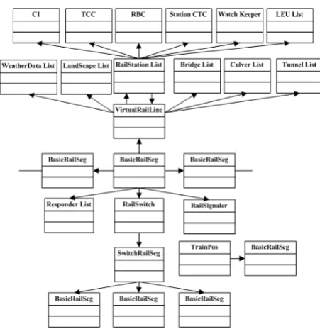
Choosing the basic line as meta-model and Scheme Three in Section 4.E as the basic-line dividing scheme, the software implementation scheme of the geographic information model can be given organized as Figure 3.
Figure 3. The class structure of the geographic line model
In Fig. 3, CI represents Computer Interlocking, TCC represents Train Control Center, RBC represents Radio Block Center, and CTC represents Centralized Traffic Control.
The geographic information model is implemented by Java programming language, and there are four key classes: BasicRailSeg, PointRailSeg, VirtualRailLine and TrainPos, which separately correspond to basic line, point switch, virtual line and coordinate of train position.
The basic line object is the cell unit of the whole geographic information model, and it is also the carrier of line parameters and trackside equipment information. The
attributes of basic line object mainly includes: the length of basic line, the connection relation with the previous and the next basic line, the line parameters and trackside equipment information expressed by linked list, corresponding virtual line, and the mapping relation to the virtual-line coordinate system expressed by linked list of interpolation points.
The point switch object is composed of three basic line objects, and it also maintains a state attribute, which is to express the direction of the switch. When the direction of the switch changed, it will re-allocate the connection relation of the three basic line objects. To express the function in detail, named the three objects as: Basic Line one, Basic Line Two and Basic Line Three, we suppose that Line One is the main line of the switch, when the switch is on normal switch position, Line Two is the next line of Line One, and Line One is the previous line of Line Two, the previous line of Line Three is null; but when the switch is on reverse switch position, the connection relation is changed, Line Three is the next line of Line One, Line One is the previous line of Line Three, and the previous line of Line Two is null.
Virtual line object is the carrier of the information of large-span equipments or buildings, whose attributes are mainly the information of equipments and buildings expressed by linked list.
TrainPos object is abstraction and packaging of the coordinate points in the basic-line coordinate system cluster, whose attributes mainly includes: the reference of corresponding basic line object and one-dimensional curvilinear coordinate. The methods of TrainPos class mainly includes: 1) methods for moving the coordinate point along the railway line (can crossover different basic lines), the train model and other models that need to change the coordinates can call these methods; 2) methods for querying the line parameters and equipment information at nearby location. The train model and other models that need geographic information can call these methods. All these methods are the main interfaces for interacting between the train model and the geographic information model.
The data related to the geographic information model is stored in database. While system initiates, all related data is read from the database, then objects of basic line, point switch, virtual line and so on are constructed. At last, the connection relations among these objects need to be built.
B. The Architecture of the Simulation System
simulation model workstations and real equipments is connected by General Interface platform.
The geographic information model is a model running on the simulation model workstations. It is a software entity, which works as the supporting environment for train dynamic model running. In the supporting system workstations, the database of geographic information provides data to instantiate the geographic information model.
VI. SIMULATION RESULT
According to the modeling method above, we use real railway-line data, and java programming language to develop the simulation software. While the system is
running, the interface diagram which shows the states of the whole railway line and all of trains. Using different railway-line data, the train running diagram is different, not only the topologic of the railway line, but also the state of the train, for the train control system is different.
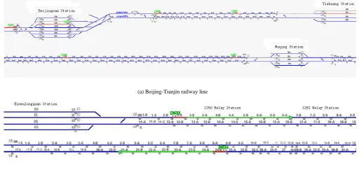
The real railway-line data uses Beijing-Tianjin railway line data, and the train control system uses CTCS level 2 system, the train running diagram shows in Fig. 4(a); Then we change the conditions: the real railway-line data uses Wuhan-Guangzhou railway line data, and the train control system uses CTCS level 3 system, the train running diagram shows in Fig. 4(b)
(a) Beijing-Tianjin railway line
(b) Wuhan-Guangzhou railway line
Figure 4. train running diagram
In Fig. 4, the white line represents the route handled by CI for train, the red line represents the track occupied by train, and the green line means the movement authority for train. The CTCS level 3 systems can give the movement authority for train, but CTCS level 2 system can’t. The running situation of the system shows that the geographic information model can effectively provide the geographic information needed by train running.
To verify the geographic information model and related modeling method, real data of the Wuhan-Guangzhou railway line which we just use five stations and four inter-sections has been used to instantiate the model. And a set of real train control equipments (TCC, CI, RBC, ATP, etc.) as well as a series of real equipment software have been embedded into the simulation platform. The simulating results of a lot of typical application scenes show that the geographic information model can indeed provide effective support for running of real equipments and software. Since running real
equipments and software needs real input environment and system logic, that running result can give powerful evidence of the model effectiveness.
For any real equipment, there is corresponding model in the virtual simulation system, hence, the real equipment can be easily embedded to the simulation platform and the real equipment and the virtual model can be replaced by each other conveniently. By this way, the effectiveness of the models and the system architecture can be verified.
After verification, this simulation platform has been applied for the test of CTCS level 3 equipments and system. Through tests with this platform, some mistakes of the real software, such as TCC software (new developed), have been found. For example, when the route has been established, the track circuit code sent by TCC is wrong. This fact further shows the effectiveness of the geographic information model.
railway line with the CTCS level 3 system. With the test and verification of the equipments which will be applied to the railway line, the design errors and mistakes can be found effectively; hence it can significantly enhance the safety of the train control system.
VII. CONCLUSION
According to the requirement of CTCS level 3 hardware-in-the-loop simulation systems, a geographic information model using meta-modeling method is proposed in this paper. The basic line object is chosen as the meta-model and a coordinate system for conveniently expressing train position is established. Based on the coordinate system, how to describe line parameters and equipment information is given. And the dividing method of basic lines and its comparison with other dividing methods are researched specially. The geographic information model using this modeling method provides effective running environment for the CTCS level 3 hardware-in-the-loop simulation platform. It also provides a solid base for realizing auto test of train control equipments and system.
It is expected that the development of train control equipments will be significantly accelerated with the help of the proposed model, and the safety level will be remarkably enhanced as well.
ACKNOWLEDGMENT
This work was supported by the Research Foundation of the Ministry of Railways and Tsinghai University (RFMOR &THU) under Grant T200705. We wish to thank Xiang Yan for his helpful discussion.
REFERENCES
[1] Weiwei Zhang, Yong Zhang. Study on simulation test platform of on-board equipment of CTCS Level 3. Railway Computer Application(RCA), vol 1, January 2007, pp:4-7. [2] Zhao Huibing, Liu Huan and Pang Dongming. Study on
Hardware-In-the-Loop Simulation System During Design and Testing of Intermittent Track-to-Train Data Transmission Equipment:BTM [J]. The Eigth International Conference on Electronic Measurement and Instruments. ICEMI’2007.
[3] Yingjie Wang, Limin Jia, Yong qin and Dongrui Wang, “Geographic Information System applied on Railway”, China Railway Science, vol 23, October 2002, pp: 23-26. [4] Mingde Liu and Jiebin Lin, Theory and practice of
Geographic Information Systems GIS, Tsinghua University Press, Beijing, December 2006, pp: 1-38.
[5] Jinshan Pan, Shaoquan Ni, and Hongxia Lv, “The research on the train operation Simulation System based on GIS”, Railway Computer Application, vol 16, March 2007, pp: 1-4.
[6] Yuan Mao, Jie Liu and Bohu Li, Research on modeling method based on the model of complex systems”, Journal of System Simulation, vol. 14, April 2002, pp: 450-454. [7] Senfa Chen, Theory and methods on modeling complex
systems, Southeast University Press, Nanjing, April 2005, pp:190-195.
[8] Metamodeling—Rapid Design and Evolution of Domain-Specific Modeling Environments.Dissertation of Nashville Tennessee,1999.
[9] Guiyan Jiang, Weigang Zhu, and Haifeng Guo. Application of Dynamic Segmentation Technology in Urban Geographic Information System for Transportation.
Http://www.cnki.net.
First A. Linyan TU
Linyan Tu was born in Nan Chang, Jiang Xi province, China in 1984. She is a candiate for master degree in the department of automation in Tsinghua University, and she is expected to be graduated in July 2009. she received her B.S. degree in the department of Electronic Engineering in Harbin Engineering University.
She is a postgraduate in Department of Automation, Tsinghua University, Beijing 100084, China.
Her main research interest: simulation and modeling technology in train control system.
Second B. Wei DONG
Wei Dong was born in Wuhan, China in 1978. He received his B.S. and Ph.D. all from the Automation Department of Tsinghua University, in 2000 and 2006, respectively. His main research areas are large-scale distributed simulation and modeling, systemic fault modeling and test and intelligent home network.
He is with the Department of Automation, and Tsinghua National Laboratory for Information Science and Technology, Tsinghua University, Beijing, China. His current research interest is in the area of simulation and modeling of train control system.
Dr. Dong is IEEE member.
Third C. Yindong JI
Yindong Ji was born in Beijing, China in 1962. He received his B.S. and M.S. all from the Automation of Tsinghua University, in 1985 and 1989, respectively. His main research areas are digital signal process, fault diagnosis, modeling & simulations. He is a member of IEEE.
Prof. JI is with the Department of Automation, and Tsinghua National Laboratory for Information Science and Technology, Tsinghua University, Beijing, China. He has published over 40 papers in journals. His current research interest is in the area of train control system of high speed railway.
Fourth D. Xinya SUN
Xinya Sun was born in Jiangsu, China in 1964. He got his B.S. and M.S. from Automation Department, Tsinghua University , in 1988 and 1993.
He is with the Department of Automation, and Tsinghua National Laboratory for Information Science and Technology, Tsinghua University, Beijing, China.