Evaluation of Performance of In-Use Firefighters’ Protective
Clothing Using on-Destructive Tests
A Thesis Submitted to the College of Graduate Studies and Research In Partial Fulfilment of the Requirements
For the Degree of Doctor of Philosophy In the Department of Mechanical Engineering
University of Saskatchewan Saskatoon
By
Moein Rezazadeh
i
PERMISSIO TO USE
In presenting this dissertation in partial fulfilment of the requirements for a Postgraduate degree from the University of Saskatchewan, I agree that the Libraries of this University may make it freely available for inspection. I further agree that permission for copying of this dissertation in any manner, in whole or in part, for scholarly purposes may be granted by the professor or professors who supervised my dissertation work or, in their absence, by the Head of the
Department or the Dean of the College in which my thesis work was done. It is understood that any copying or publication or use of this thesis/dissertation or parts thereof for financial gain shall not be allowed without my written permission. It is also understood that due recognition shall be given to me and to the University of Saskatchewan in any scholarly use which may be made of any material in my dissertation.
Requests for permission to copy or to make other uses of materials in this dissertation in whole or part should be addressed to:
Head of the Department of Mechanical Engineering University of Saskatchewan
Saskatoon, Saskatchewan S7N 5A9 Canada
OR
Dean
College of Graduate Studies and Research University of Saskatchewan
107 Administration Place
Saskatoon, Saskatchewan S7N 5A2 Canada
ii
DISCLAIMER
The names of certain commercial products were exclusively used to meet the dissertation and/or exhibition requirements for the degree of Doctor of Philosophy at the University of
Saskatchewan. Reference in this dissertation to any specific commercial products, process, or service by trade name, trademark, manufacturer, or otherwise, does not constitute or imply its endorsement, recommendation, or favouring by the University of Saskatchewan. The views and opinions of the author expressed herein do not state or reflect those of the University of
iii
ABSTRACT
Firefighters’ coats and pants, referred to as firefighters’ protective clothing in this research, are made of similar fabrics and often include three layers: an outer shell, a moisture barrier, and a thermal liner. Minimum requirements of firefighters’ protective clothing performance have been clearly established by various national and international standards for new clothing to ensure the reasonable safety of firefighters. However, there are no clear guidelines on the requirements for continuing performance of firefighters’ protective clothing. In general, the protection offered by firefighters’ protective clothing is expected to deteriorate over time, but it is still uncertain how destructive different exposures are and how long a piece of firefighters’ protective clothing can continue to protect a firefighter to an acceptable level.
Non-destructive techniques are preferable in order to investigate how the performance of protective clothing may change with time since this allows firefighters’ protective clothing to return to service after a test. These non-destructive methods, which could be used to monitor the level of deterioration in firefighters’ protective clothing performance and to make decisions on retirement of individual pieces of protective clothing, would be extremely useful for fire departments in Canada and other countries.
Thermal exposure is an important factor in ageing of firefighters’ protective clothing during firefighting operations. Outer shell and moisture barrier specimens made of common fabrics used in construction of firefighters’ protective clothing, and of different colours, were exposed to different levels of thermal exposure simulated using a cone calorimeter in single and multiple stages. Tensile strength of outer shell specimens, and tear strength, water vapour transmission rate, and water penetration pressure of moisture barrier specimens, which are critical aspects of performance of firefighters’ protective clothing, were measured. In order to explain the changes in performance after thermal exposure, the temperature profile of specimens during each thermal exposure was recorded. Furthermore, thermogravimetric analysis for each specimen material was carried out and images of the surface of specimens were obtained using scanning electron
microscope. The test results demonstrated that tensile strength of outer shell specimens deteriorated faster than other aspects of performance.
iv
Two non-destructive techniques, colour measurement and near infrared spectroscopy, were implemented to correlate tensile strength of outer shell specimens with discoloration and
reflectance spectrum. Two types of correlation between tensile strength and colour change were identified among the tested fabrics, depending on the initial fabric colour, which could be a basis to develop numerical models to predict tensile strength of outer shell specimens. Linear
predictive equations were developed using a numerical code based on regression analysis, which correlated tensile strength with reflectance of outer shell specimens within the wavelength region of 1500-2500 nm. A three-variable model predicted tensile strength of thermally aged test
specimens, the tensile strength of which were 600 N and higher, with a relative error of up to 10%. For test specimens with tensile strength of about 300 N, the relative error was 55%. The difference in error percentage was related to a gap in training data points for the model within the tensile strength range of 300 - 600 N.
v
ACKOWLEDGMETS
I would like to sincerely thank Prof. David Torvi for his trust in me and continuous
supervision during my study. His encouragement and financial support to attend conferences is truly appreciated. Mr. David Deutcher and Rick Retzleff were very supportive in set-up and troubleshooting of the equipment in the laboratory. I learned many technical points from them. I would like to specially thank Prof. Scott Noble from Department of Chemical and Biological Engineering for his guidance in infrared spectroscopy and statistical analysis. His wealth of knowledge and strong passion for research were really inspiring. Technical support from Mr. Robert Peace in using scanning electron microscope and Mr. Hans Steinmetz in conducting mechanical strength testing is appreciated.
Mr. Guosheng Liu from Department of Biology and Mr. Louis Roth from Department of Chemical and Biological Engineering were very helpful in coating specimens for scanning electron microscopy and performing tensile strength tests, respectively. Kelley Neale was extremely helpful in preparing documents and paperwork for my study as an international
student. Examination of my advisory committee members is acknowledged. I extend my heartfelt appreciation to nice and kind people of Saskatoon for welcoming and accepting me in their community. Socializing with them was a great experience and full of lessons for me.
Generous financial support from Natural Science and Engineering Research Council of Canada (NSERC), Department of Mechanical Engineering, and College of Graduate Studies and Research at the University of Saskatchewan is deeply appreciated. Donation of fabrics by Difco Performance Fabrics (now TenCate Protective Fabrics) and Stedfast Inc. is gratefully
acknowledged.
To my three special life gifts from God:
vii
TABLE OF COTETS
Page PERMISSION TO USE ... i DISCLAIMER ... ii ABSTRACT ... iii ACKNOWLEDGMENTS ... vTABLE OF CONTENTS ... vii
LIST OF TABLES ... ix
LIST OF FIGURES ... xi
LIST OF SYMBOLS ... xviii
LIST OF ABBREVIATIONS ... xix
1.INTRODUCTION ... 1
1.1. Firefighters’ protective clothing ... 1
1.2. Performance requirements for firefighters’ protective clothing ... 3
1.3. Identifying the need for this research ... 8
1.4. Ageing of firefighters’ protective clothing... 11
1.5. Potential non-destructive test methods ... 26
1.6. Scope and objectives of research ... 35
1.7. Contributions of this research to the literature ... 37
1.8. Outline of the dissertation ... 37
2.EXPERIMENTAL APPARATUS AND PROCEDURE... 39
2.1. Thermal ageing ... 39
2.2. Cone Calorimeter ... 45
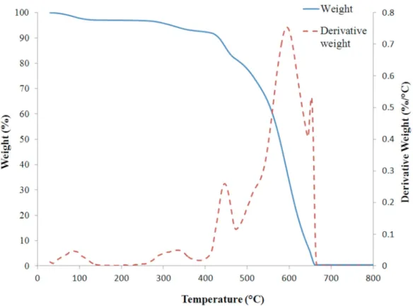
2.3. Thermogravimetric analysis (TGA) ... 48
2.4. Temperature measurement ... 49
2.5. Tensile strength tests ... 51
2.6. Tear strength tests... 52
2.7. Water vapour permeability tests ... 53
2.8. Water penetration pressure tests ... 55
viii
3.1. Preparation of specimens ... 57
3.2. Thermogravimetric analysis (TGA) ... 58
3.3. Temperature measurements... 61
3.4. Tensile tests ... 66
4.MOISTURE BARRIER EXPERIMENTS ... 78
4.1. Preparation of specimens ... 80
4.2. Thermogravimetric analysis (TGA) ... 82
4.3. Temperature measurement ... 84
4.4. Water vapour permeability test ... 85
4.5. Water penetration pressure test ... 89
4.6. Tear strength test ... 91
5.MULTI-STAGE EXPOSURE EXPERIMENTS ... 95
5.1. Preparation of specimens ... 95
5.2. Thermogravimetric analysis ... 98
5.3. Temperature measurements... 101
5.4. Tensile tests ... 104
5.5. Tear strength ... 108
5.6. Water vapour permeability test ... 112
5.7. Water penetration pressure test ... 114
6.NON-DESTRUCTIVE EXPERIMENTS ... 117
6.1. Test procedure ... 119
6.2. Colour measurement ... 122
6.3. Near infrared spectroscopy... 132
7.PREDICTING TENSILE STRENGTH OF OUTER SHELL ... 144
7.1. Correlation between tensile strength and colour measurement ... 144
7.2. Correlation between tensile strength and near infrared spectroscopy ... 151
8.CONCLUSIONS AND FUTURE WORK... 174
8.1. Conclusions ... 174
8.2. Future work ... 177
ix
LIST OF TABLES
Table Page
Table 1.1: Evaluation tests of firefighters’ protective clothing and required parameters to
report according to NFPA 1971 [2] ... 4
Table 1.2: Tensile strength of new and visibly faded specimens, required time for appearance of visible discoloration [14] ... 23
Table 1.3: Summary of research on effects of thermal ageing [9] ... 24
Table 2.1: Thermal environment 1 [56] ... 40
Table 2.2: Thermal environment 2 [56] ... 40
Table 2.3: Thermal environment 3 [56] ... 41
Table 2.4: Thermal environment 4 [56] ... 41
Table 3.1: Test matrix for outer shell specimens ... 58
Table 3.2: Temperature of Nomex® IIIA outer shell specimens in different colours after 30 s exposure to a particular heat flux ... 62
Table 4.1: Thermal exposure duration for each heat flux ... 82
Table 5.1: Duration of single-stage exposure and the equal number of 30-second stages in multiple-stage exposure to a heat flux of 20 kW/m2 ... 97
Table 5.2: Maximum temperatures (°C) achieved by different layers of ensemble during exposures to incident heat flux of 20 kW/m2 (undyed Kevlar®/PBI brown outer shell) ... 103
Table 5.3: Temperature of brown Kevlar®/PBI outer shell specimens after particular duration of exposure ... 104
Table 6.1: Mass moisture regain of unexposed yellow Nomex® outer shell specimens ... 139
Table 7.1: Wavelengths of the most accurate three-variable equation for each type of specimen ... 161
Table 7.2: Thermal exposure specification and tensile strength of blue, red, dark blue, and yellow Nomex® outer shell specimens for the purpose of interpolation ... 161
x
Table 7.4: Specifications of the three-variable equations with the highest R2a for blue
xi
LIST OF FIGURES
Figure Page
Figure 1.1: Three layers of firefighters’ protective clothing ... 2
Figure 1.2: A TPP tester (reprinted from [7] with permission) ... 5
Figure 1.3: Change in the performance of firefighters’ protective clothing with ageing [12] ... 10
Figure 1.4: Main substitution patterns... 13
Figure 1.5: Chemical structure of Nomex® ... 14
Figure 1.6: Chemical structure of Kevlar® ... 14
Figure 1.7: Chemical structure of PBI ... 14
Figure 1.8: Molecular structure of PTFE ... 15
Figure 1.9: CCHR ratings of Nomex® thermal liner specimens previously exposed to various radiant heat flux exposures using the ASTM F1939 test apparatus [14] ... 20
Figure 1.10: Tensile strength of Kevlar®/Nomex® outer shell specimens previously exposed to various radiant heat flux exposures using the ASTM F 1939 test apparatus [14] ... 20
Figure 1.11: Examples of colour fade of 60% Kevlar®/40% Nomex® outer shell specimens after different levels of thermal exposure ... 31
Figure 1.12: DIA results to correlate discoloration and tensile strength of 60% Kevlar®/40% Nomex® outer shell specimens [14] ... 32
Figure 2.1: The range of thermal conditions faced by firefighters [65] ... 42
Figure 2.2: A view of thermal condition classified as “Routine” [14] ... 42
Figure 2.3: A view of thermal condition classified as “Ordinary” [14] ... 43
Figure 2.4: A view of thermal condition classified as “Emergency” [14] ... 43
Figure 2.5: Cone calorimeter ... 45
Figure 2.6: Conical heater of a cone calorimeter ... 46
Figure 2.7: Locations of heat flux measurement carried out 25 mm under the conical heater ... 47
Figure 2.8: Distribution of generated heat flux (35 kW/m2) 25 mm under the conical heater ... 47
xii
Figure 2.10: Tensile testing machine ... 51
Figure 2.11: Specimen marking template ... 52
Figure 2.12: Position of a specimen in the clamping system in tear strength test ... 53
Figure 2.13: Water vapour permeability test apparatus ... 54
Figure 2.14: A schematic view of a test cell of the water vapour permeability test equipment ... 54
Figure 2.15: A view of a moisture barrier specimen glued to the carrier ... 55
Figure 2.16: Water penetration pressure test apparatus ... 56
Figure 3.1: TGA curve for blue outer shell specimens made of Nomex® IIIA ... 59
Figure 3.2: TGA curve for red outer shell specimens made of Nomex® IIIA ... 60
Figure 3.3: TGA curve for dark blue outer shell specimens made of Nomex® IIIA ... 60
Figure 3.4: TGA curve for yellow outer shell specimens made of Nomex® IIIA... 61
Figure 3.5: The first 30 s temperature history of the back side of the blue Nomex® IIIA specimens using the infrared thermometer during thermal exposure ... 63
Figure 3.6: The first 30 s temperature history of back side of the Nomex® IIIA red specimens using the infrared thermometer during thermal exposure ... 64
Figure 3.7: The first 30 s temperature history of the Nomex® IIIA dark blue specimens using the infrared thermometer during thermal exposure ... 65
Figure 3.8: The first 30 s temperature history of back side of the Nomex® IIIA yellow specimens using the infrared thermometer during thermal exposure ... 66
Figure 3.9: Illustration of warp and fill directions in a fabric ... 67
Figure 3.10: Tensile strength of specimens after exposure to 10 kW/m2 ... 68
Figure 3.11: Surface of an unexposed Nomex® specimen ... 69
Figure 3.12: Surface of Nomex®specimen after exposure to 10 kW/m2 for 600 s ... 69
Figure 3.13: Surface of Nomex® specimen after exposure to 10 kW/m2 for 1200 s ... 69
Figure 3.14: Surface of Nomex®specimen after exposure to 10 kW/m2 for 2400 s ... 69
Figure 3.15: Tensile strength of Nomex® specimens after exposure to 20 kW/m2 ... 70
Figure 3.16: Surface of an unexposed Nomex® specimen ... 71
Figure 3.17: Surface of Nomex® specimen after exposure to 20 kW/m2 for 30 s ... 71
xiii
Figure 3.19: Surface of Nomex® specimen after exposure to 20 kW/m2 for 300 s ... 71
Figure 3.20: Tensile strength of Nomex® specimens after exposure to 30 kW/m2 ... 72
Figure 3.21: Surface of an unexposed Nomex® specimen ... 73
Figure 3.22: Surface of Nomex® specimen after exposure to 30 kW/m2 for 15 s ... 73
Figure 3.23: Surface of Nomex® specimen after exposure to 30 kW/m2 for 30 s ... 73
Figure 3.24: Surface of Nomex® specimen after exposure to 30 kW/m2 for 60 s ... 73
Figure 3.25: Tensile strength of specimens after exposure to 40 kW/m2 ... 74
Figure 3.26: Surface of an unexposed Nomex® specimen ... 74
Figure 3.27: Surface of Nomex® specimen after exposure to 40 kW/m2 for 10 s ... 74
Figure 3.28: Surface of Nomex® specimen after exposure to 40 kW/m2 for 20 s ... 75
Figure 3.29: Surface of Nomex® specimen after exposure to 40 kW/m2 for 30 s ... 75
Figure 3.30: Average tensile strength of Nomex® specimens after thermal exposure to particular heat flux for specific duration ... 77
Figure 4.1: Layers of firefighters’ protective clothing ... 78
Figure 4.2: Transmitted heat flux through Crusader®790 outer shell when the copper calorimeter is in direct contact with the fabric and when there is a 3.2 mm (1/8 in.) spacer between them ... 81
Figure 4.3: TGA curve for membrane ePTFE side of Stedair® 4000 moisture barrier specimens ... 83
Figure 4.4: TGA curve for substrate (Nomex®) side of moisture barrier specimens ... 84
Figure 4.5: Temperature history of the back side of Stedair® 4000 moisture barrier specimens during thermal exposure ... 85
Figure 4.6: Water Vapour Transmission Rate (WVTR) of moisture barrier specimens... 86
Figure 4.7: The polymeric layer of a membrane of an unexposed specimen ... 87
Figure 4.8: The polymeric layer of a membrane of a specimen exposed to 10 kW/m2 for 120 s ... 87
Figure 4.9: ePTFE fibres in the membrane of the unexposed moisture barrier specimen ... 88
Figure 4.10: ePTFE fibres in the membrane of the specimen exposed to 10 kW/m2 for 120 s ... 88
xiv
Figure 4.11: ePTFE fibres in the membrane of the specimen exposed to 10 kW/m2 for
300 s ... 88
Figure 4.12: ePTFE fibres in the membrane of the specimen exposed to 15 kW/m2 for 60 s ... 88
Figure 4.13: Surface of specimen after exposure to 20 kW/m2 for 300 s ... 89
Figure 4.14: Required pressure for water penetration for moisture barrier specimens ... 90
Figure 4.15: Tear strength of moisture barrier specimens after thermal exposure ... 93
Figure 5.1: TGA curve for brown Kevlar®/PBI outer shell fabrics ... 99
Figure 5.2: TGA curve for black Kevlar®/PBI outer shell fabrics ... 99
Figure 5.3: TGA curve for membrane side of Stedair®3000 moisture barrier specimen ... 100
Figure 5.4: TGA curve for substrate side of moisture barrier specimen ... 101
Figure 5.5: Temperature history of front and back sides of outer shell and moisture barrier layers of specimens during exposure to 20 kW/m2 for three consecutive stages ... 102
Figure 5.6: Tensile strength of brown Kevlar®/PBI outer shell fabric along fill direction ... 106
Figure 5.7: Tensile strength of brown Kevlar®/PBI outer shell fabric along warp direction ... 106
Figure 5.8: Tensile strength of black Kevlar®/PBI outer shell fabric along fill direction ... 107
Figure 5.9: Tensile strength of black Kevlar®/PBI outer shell fabric along warp direction ... 107
Figure 5.10: Tensile strength of brown and black Kevlar®/PBI outer shell specimens as percent of initial tensile strength after single exposure for particular duration ... 108
Figure 5.11: Tear strength of Stedair® 3000 moisture barrier fabrics along fill direction after single-stage exposure to 20 kW/m2 ... 110
Figure 5.12: Tear strength of Stedair® 3000 moisture barrier fabrics along warp direction after single-stage exposure to 20 kW/m2 ... 110
Figure 5.13: Tear strength of Stedair® 3000 moisture barrier fabrics along fill direction after multi-stage exposure to 20 kW/m2 ... 111
Figure 5.14: Tear strength of Stedair® 3000 moisture barrier fabrics along warp direction after multi-stage exposure to 20 kW/m2 ... 111
Figure 5.15: Average tear strength of Stedair® 3000 moisture barrier specimens after single and multi-stage exposures as percentage of tear strength for an unexposed specimen ... 112
xv
Figure 5.16: WVTR of Stedair® 4000 specimens after single-stage and multi-stage
exposures ... 114
Figure 5.17: Required pressure for water penetration in Stedair® 4000 after single-stage and multi-stage exposures ... 115
Figure 6.1: The RGB colour system [14] ... 120
Figure 6.2: Conversion of discoloration of specimens to a representative colour ... 120
Figure 6.3: Interrogation area and regions of interest for colour measurement ... 121
Figure 6.4: The trend of discoloration in Nomex® outer shell fabrics of different colour ... 124
Figure 6.5: Colour change in Nomex® fabrics of different colours after exposure to 10kW/m2 for particular duration ... 125
Figure 6.6: Colour change in blue Nomex® specimens ... 126
Figure 6.7: Colour change in red Nomex® specimens ... 127
Figure 6.8: Colour change in dark blue Nomex® specimens ... 128
Figure 6.9: Colour change in yellow Nomex® specimens ... 128
Figure 6.10: Colour change in brown Kevlar®/PBI specimens after single-stage and multi-stage exposures ... 129
Figure 6.11: Colour change in black Kevlar®/PBI specimens after single-stage and multi-stage exposures ... 130
Figure 6.12: Colour difference in regions 1 (central area) and 2 (whole area) for brown specimens ... 131
Figure 6.13: Colour difference in regions 1 (central area) and 2 (whole area) for black specimens ... 132
Figure 6.14: Reflectance spectrum of unexposed Nomex® specimens of different colours ... 133
Figure 6.15: Reflectance spectrum for blue Nomex® specimens after thermal exposure to 10 kW/m2 ... 134
Figure 6.16: Reflectance spectrum for blue Nomex® specimens after thermal exposure to 20 kW/m2 ... 135
Figure 6.17: Reflectance spectrum for blue Nomex® specimens after thermal exposure to 30 kW/m2 ... 136
xvi
Figure 6.18: Reflectance spectrum for blue Nomex® specimens after thermal exposure to
40 kW/m2 ... 136 Figure 6.19: Repeatability of reflectance spectrum of specimens after different levels of
thermal exposure ... 137 Figure 6.20: Effect of moisture on reflectance spectrum of yellow Nomex® unexposed
specimens ... 139 Figure 6.21: Reflectance spectrum for brown Kevlar®/PBI specimens after thermal
exposure to 20 kW/m2 ... 140 Figure 6.22: Reflectance spectrum for black Kevlar®/PBI specimens after thermal exposure
to 20 kW/m2 ... 141 Figure 6.23: Effect of single-stage and multi-stage exposures on reflectance spectrum of
black Kevlar®/PBI specimens ... 142 Figure 7.1: Correlation of tensile strength with colour difference for blue Nomex®
specimens ... 146 Figure 7.2: Correlation of tensile strength with colour difference for dark blue Nomex®
specimens ... 146 Figure 7.3: Correlation of tensile strength with colour difference for black Kevlar®/PBI
specimens ... 147 Figure 7.4: The first type of colour change and its correlation with tensile strength... 147 Figure 7.5: Correlation of tensile strength with colour difference for red Nomex®
specimens ... 149 Figure 7.6: Correlation of tensile strength with colour difference for yellow Nomex®
specimens ... 149 Figure 7.7: Correlation of tensile strength with colour difference for brown Kevlar®/PBI
specimens ... 150 Figure 7.8: The second type of colour change and its correlation with tensile strength ... 150 Figure 7.9: Range of adjusted R2 values in equations made of a particular number of
variables for blue Nomex® specimens ... 154 Figure 7.10: Range of adjusted R2 values in equations made of a particular number of
xvii
Figure 7.11: Range of adjusted R2 values in equations made of a particular number of
variables for dark blue Nomex® specimens ... 156
Figure 7.12: Range of adjusted R2 values in equations made of a particular number of variables for yellow Nomex® specimens ... 157
Figure 7.13: Range of adjusted R2 values in equations made of a particular number of variables for brown Kevlar®/PBI specimens ... 158
Figure 7.14: Range of adjusted R2 values in equations made of a particular number of variables for black Kevlar®/PBI specimens ... 159
Figure 7.15: Accuracy of the three -variable model for blue Nomex® specimens to predict tensile strength of interpolating points ... 162
Figure 7.16: Accuracy of the three-variable model for red Nomex® specimens to predict tensile strength of interpolating points ... 163
Figure 7.17: Accuracy of the three-variable model for dark blue Nomex® specimens to predict tensile strength of interpolating points ... 164
Figure 7.18: Accuracy of the three-variable model for yellow Nomex® specimens to predict tensile strength of interpolating points ... 165
Figure 7.19: The three-variable model for brown Kevlar®/PBI specimens ... 166
Figure 7.20: The three-variable model for black Kevlar®/PBI specimens ... 166
Figure 7.21: Replication of data points by the best equations made of 3, 5, 7, and 10 wavelengths for blue specimens ... 168
Figure 7.22: The three-variable model based on wavelengths in region 1500 – 1900 nm ... 170
Figure 7.23: The three-variable model based on wavelengths in region 1900 – 2500 nm ... 170
xviii
LIST OF SYMBOLS
English LettersBe Magnitude of blue component of colour of an exposed specimen
Bu Magnitude of blue component of colour of an unexposed specimen
Ge Magnitude of green component of colour of an exposed specimen
Gu Magnitude of green component of colour of an unexposed specimen
m Number of observations of a dependent variable n Number of independent variables
p Total number of coefficients of independent variables
Re Magnitude of red component of colour of an exposed specimen
Ru Magnitude of red component of colour of an unexposed specimen
R2 Coefficient of determination
R2a Adjusted coefficient of determination
t12 Required time for a copper calorimeter to undergo temperature rise of 12°C
t24 Required time for a copper calorimeter to undergo temperature rise of 24°C
X An independent variable Y A dependent variable
Ŷ Predicted value of a dependent variable Ῡ Mean of real values of a dependent variable
Greek Letters
α A coefficient of an independent variable
∆Colour Colour difference from the colour of an unexposed specimen ∆tn Duration of the nth stage of the exposure
∆ttotal Total duration
xix
LIST OF ABBREVIATIOS
CRE Constant-Rate-of-Extension
CCHR Conductive and Compressive Heat Resistance DIA Digital Image Analysis
ePTFE expanded Polytetrafluoroethylene FTIR Fourier Transform Infrared PBI Polybenzimidazole
SCBA Self Contained Breathing Apparatus SEM Scanning Electron Microscope
RGB Red-Green-Blue
TGA Thermogravimetric Analysis THL Total Heat Loss
TPP Thermal Protective Performance WVTR Water Vapour Transmission Rate
1
1.
ITRODUCTIO
11.1.
Firefighters’ protective clothing
Fires have always been a major source of damage all over the world. On average, 59,936 fires occurred in Canada annually from 1993 to 2002, which caused 374 deaths, 3072 injuries, and $1.2 billion in property losses per year [1]. When fires occur, firefighting has always been considered as an important way to decrease the level of damage. The type of firefighting which is involved in buildings, aircraft interiors, vehicles, vessels, and generally enclosed structures is called structural firefighting [2]. Firefighting to deal with fire that occurs in vegetation and prairie is considered as wildland firefighting [3]. This research concentrates on elements of protective clothing used in structural and wildland firefighting.
To protect firefighters and enable them to work efficiently under severe conditions, they are equipped with firefighters’ protective clothing. Firefighters’ protective clothing plays an
important role in mitigating firefighters’ injuries. Firefighters’ protective clothing is a general term which includes pants, coats, hoods, helmets, gloves, boots and self-contained breathing apparatus. In this dissertation, the term firefighters’ protective clothing will be used to refer to coats and pants since they are the focus of this research. Firefighters’ protective clothing should protect firefighters from the impact of flame and heat and prevent the penetration of water and other external liquids towards the body. It should be strong enough not to tear easily when it is in contact with sharp and abrasive surfaces and when subjected to friction involved in some
movements like crawling. Ease of mobility and flexibility during firefighting operation, and high visibility in hazy atmospheres and both day and night time are other important specifications of firefighters’ protective clothing. Furthermore, the clothing should help to regulate some
physiological reactions of the body like perspiration and high heart rate in hot environments and during hard work. Not all these specifications can be completely met by only one layer of firefighters’ protective clothing. Multi-layer structure of firefighters’ protective clothing also provides supplementary insulation by tiny air spaces between layers and subsequently, more protection without any extra weight or cost associated with fabrics.
1
2
The moisture and heat flow to a firefighters’ body is restricted by firefighters’ protective clothing. Similarly, the dissipation of heat generated by physiological body functions such as metabolism and perspiration is limited. So, highly insulating firefighters’ protective clothing poses some problems for heat and moisture removal from the body, which may lead to an increase in body temperature, steam burns, heat stress and in severe conditions, death [4]. Also, higher heat protection may necessitate thicker layers of fabrics, which makes the clothing heavier and consequently, limits the agility of firefighters. Therefore, there is a trade-off between
protection of the firefighter’s body from thermal exposure and heat removal from their body. Firefighters’ protective clothing is typically composed of three layers, the outer shell, the moisture barrier, and the thermal liner (Figure 1.1). The outer shell is the outermost layer and the first line of defence. Its role is protection against heat, flame, cuts, and abrasion. The moisture barrier is the middle layer and prevents external liquids such as water and chemicals, bloodborne pathogens, and viral agents from penetrating into the body. Some types of moisture barriers contain small pores which prevent passage of liquid drops, but allow vapour diffusion and decrease the risk of steam burns to some extent. The thermal liner is the innermost layer and acts as an insulating layer. It plays a major role in thermal protection and protects firefighters from heat or cold. The slippery surface of thermal liner in contact with the skin provides firefighters with ease of donning and doffing, and assists in agility and mobility during firefighting
operations. Some types of thermal liners have the additional advantage of wicking away perspiration.
Figure 1.1: Three layers of firefighters’ protective clothing Outer shell
Moisture barrier
3
1.2.
Performance requirements for firefighters’ protective clothing
The standards for protective clothing for new structural firefighting (e.g., NFPA 1971 [2] and CGSB-155.1 [5]), describe the minimum requirements for new firefighters’ protective clothing and the test methods to evaluate these requirements. All required tests in NFPA 1971 to evaluate firefighters’ protective clothing and the reported properties in the tests are summarized in
Table 1.1. However, there is no quantitative standard and test for in-use firefighters’ protective clothing. Similar test procedures to NFPA 1971 will be used to assess the changes in
characteristic parameters of used firefighters’ protective clothing in this dissertation.
In terms of thermal performance, new firefighters’ protective clothing is tested for flame resistance, thermal shrinkage resistance, Thermal Protective Performance (TPP), Thermal Heat Loss (THL), and Conductive and Compressive Heat Resistance (CCHR). The flame resistance test is applicable to all layers of firefighters’ protective clothing. In the flame resistance test, a specimen is exposed vertically above a methane flame, the height of which is 38 mm, for 12 s. Then, the flame source is removed and afterflame time is recorded. Afterflame time is the time for which the specimen continues to burn with flame. Char length, the length of visible damage along the fabric edge, is also measured. For all new fabrics, afterflame time should not exceed 2 s on average and no evidence of melting or dripping should be observed during exposure to flame. Also, the char length should not be longer than 100 mm on average.
The thermal shrinkage resistance test is applicable to all layers of firefighters’ protective clothing. Specimens are heated inside an oven, the temperature of which is kept at 260°C, for 5 min. Then, the specimen is checked for any evidence of melting or dripping. The specimen width and length are measured to calculate the average percentage of change in both dimensions. The maximum allowable percentage of shrinkage in any direction is 10%.
4
Table 1.1: Evaluation tests of firefighters’ protective clothing and required parameters to report according to NFPA 1971 [2] Test Property to be reported Application Composite specimen Outer shell Moisture barrier Thermal liner Flame resistance Afterflame time &
char length * * *
Heat and thermal shrinkage resistance
Percent change in width
and length * * *
Thermal Protective Performance (TPP)
Product of exposure energy heat flux and estimated time to
second-degree burn
*
Total Heat Loss (THL)
Average total heat loss, intrinsic thermal resistance, intrinsic evaporative resistance * Conductive and Compressive Heat Resistance (CCHR)
Required time for the test sensor to achieve a temperature rise of 24°C
*
Tear resistance Tear resistance * * *
Cleaning shrinkage resistance
Percent change in width
and length * * *
Breaking strength Required force to break
the specimen *
Water absorption resistance
The percent of absorbed
water *
Water penetration
resistance Appearance of any water *
Liquid penetration
resistance Appearance of any liquid *
Viral penetration
resistance Appearance of any broth *
Light degradation
resistance Appearance of any water *
Whole garment liquid penetration
A diagram indicating the locations of any liquid
leakage
Whole garment
5
Figure 1.2 illustrates an NFPA 1971 standard TPP tester. In the TPP test, a specimen is composed of all layers of firefighters’ protective clothing. The specimen is exposed to a heat flux of 84 kW/m2 (roughly 2 cal/(cm2·s)). A sensor is placed at the back of the specimen. It measures transferred energy from the heat source to the back of the specimen. Temperature rise detected by the sensor is compared with benchmark data [6] to estimate required time for a second degree burn to human skin. TPP value is defined as the total incident heat energy on the specimen per unit surface area at the point of second degree burn and is calculated by multiplication of the incident heat flux and the estimated required time for second degree burn. The minimum TPP value for new firefighters’ protective clothing is 35 cal/cm2. However, higher TPP values do not mean better overall protection for firefighters. Even though firefighters’ protective clothing should insulate the body from external heat (implied by higher TPP value), it should allow dissipation of metabolic heat from the interior of the garment to the outside environment.
Figure 1.2: A TPP tester (reprinted from [7] with permission)
Heat stress is an important issue in industries, especially in which workers are required to wear semi-permeable or impermeable protective clothing. Firefighters usually work in hot and humid environments and sometimes are involved in hard physical work, which can increase the body core temperature. To reduce the heat accumulation in the body and consequently
temperature rise, the body attempts to mitigate this temperature increase through physiological reactions such as sweating. Since some firefighters’ protective clothing is impermeable to water and some chemical liquids, the Total Heat Loss (THL) test is included in the NFPA 1971 standard to measure the loss of heat to outside the clothing by diffusion of water vapour and
6
conduction of heat through the three layers of firefighters’ protective clothing. Total heat loss value is in fact an indicator of the capability of the firefighters’ protective clothing in heat stress reduction.
A specimen consisting of the three layers of the firefighters’ protective clothing is placed on a hot test plate and air flows over the specimen and the test plate. The temperature of air flow and the test plate is kept constant during the experiment. Conductive (dry) heat loss is measured by the required energy to maintain the test plate temperature constant. The evaporative (wet) heat loss is measured similarly, but the test plate is uniformly wetted with water before the test. A new composite specimen of firefighters’ protective clothing should have minimum total heat loss of 205 kW/m2.
Firefighters’ protective clothing, especially in shoulder and knee areas, can come in contact with hot surfaces due to crawling and other activities during firefighting. The Conductive and Compressive Heat Resistance (CCHR) test is performed on a specimen composed of three layers of firefighters’ protective clothing to evaluate this aspect of performance. The composite
specimen is placed on a hot surface maintained at 280°C under a pressure of 140 g/cm2 (2 psi) for the shoulder area specimens and 562 g/cm2 (8 psi) for the knee area specimens. In a similar procedure to TPP test, a sensor is placed at the back of the specimen. The required time for a temperature rise of 24°C relative to initial temperature is recorded as the CCHR rating. For a new composite specimen, the CCHR rating should be higher than 25 s.
Mechanical strength of all of layers of firefighters’ protective clothing is tested by measuring tear resistance. In the tear resistance test, a specimen is slit in the centre and is pulled by jaws of a tensile testing machine. The required force to continue the tear is recorded. The minimum tear strength of an outer shell fabric should be 100 N. The minimum requirement for moisture barrier and thermal liner fabrics is 22 N. All layers of firefighters’ protective clothing should also be tested for cleaning shrinkage resistance. Specimens are washed for five cycles using a specific washing and drying procedure. The percentage of change in each dimension should not exceed 5%.
Some tests are only applicable to one specific layer of firefighters’ protective clothing. Water absorption resistance and breaking strength tests are only applicable to the outer shell layer. In the water absorption resistance test, a specimen is placed in an embroidery hoop and a 500 mL volume of distilled water is sprayed onto the specimen. The water absorption percentage is
7
calculated and should not be more than 30% for a new outer shell. The breaking strength of an outer shell specimen is measured using a tensile testing machine. A new outer shell specimen shall have a minimum breaking strength of 623 N.
Water, liquid, and viral penetration, and degradation resistance tests are only conducted for the moisture barrier layer. In the resistance to water penetration test, a moisture barrier specimen is placed between two clamping cylinders and hydraulic pressure is applied to the underside of the specimen. For new specimens, no evidence of water shall appear on the other side of the specimen before the pressure reaches 172 kPa. In addition, specimens are checked against five liquids: aqueous film-forming foam, battery acid, fire-resistant hydraulic fluid, surrogate gasoline fuel, and swimming pool chlorinating chemical. In the resistance to liquid penetration test, a specimen acts as a partition in front of the hazardous liquid in a horizontal cylindrical test cell. The test takes 60 min. in total. In the first 5 min. of the test, the liquid pressure is the same as ambient pressure. Then, the liquid pressure is increased to 13.8 kPa gauge for 1 min. For the remaining 54 min. of the test, the liquid pressure is kept at ambient pressure. During the test, no visible penetration of the liquid should be observed on the specimen surface in the viewing side of the test cell. Using the same equipment and pressure/time sequence, moisture barrier
specimens are monitored for resistance to viral penetration. Instead of specified liquids, as in the liquid penetration resistance test, the test cell is filled with bacteriophage nutrient broth (Phi-X). The broth closely simulates blood-borne pathogens’ size, morphology, and stability. A new moisture barrier should be impermeable to broth during the test.
In the light degradation resistance test, a moisture barrier specimen is exposed to simulated daylight radiation using a xenon arc lamp and appropriate filters. The specimen is aged in a test chamber under specified temperature and relative humidity for 40 hr. After 4 hr of conditioning in a dark environment, it is exposed to a pressure of 13.8 kPa (2 psi) under a column of water for 1 min. No water should appear on the surface of the specimen.
Resistance to liquid penetration is so important that in addition to tests on individual layers of firefighters’ protective clothing, the complete set of firefighters’ protective clothing is also tested. The purpose of a liquid penetration test on the whole garment is detection of leakage or absorption of liquid on the whole ensemble, especially around seams, zippers, and areas which are in close contact with gloves, boots, hoods, and respiratory protective equipment. The whole firefighters’ protective clothing is worn on a mannequin already covered by a liquid-absorptive
8
garment. Five nozzles are positioned on the top and the bottom of the mannequin. The
mannequin is exposed to sprayed water from the nozzles in four orientations for 5 min. each. At the end of the test, the firefighters’ protective clothing is removed from the mannequin and is inspected for any evidence of liquid penetration on the liquid-absorptive garment and individual layers of the specimen. The location of leakage is identified on a diagram of the mannequin. No evidence of wetting should be observed during inspection.
1.3.
Identifying the need for this research
As was discussed, this specialized clothing should meet a number of performance
requirements in thermal protection, mechanical strength, and liquid penetration resistance and the minimum level of each aspect of performance is established clearly by standards such as NFPA 1971 [2] and CGSB-155.1 [5]. Although these aspects of performance may change differently after exposure to various external factors, performance of firefighters’ protective clothing gradually deteriorates in general. Therefore, firefighters’ protective clothing reaches its retirement age when its performance falls below a critical level. This critical level is not clear and in some cases may not be even visible to the naked eye.
Useful life (service life) can be defined as the period of time during which the firefighters’ protective clothing provides acceptable protection. The useful life of firefighters’ protective clothing depends on a number of factors including the type of materials from which it is
constructed, the number, duration, and intensity of destructive exposures which the clothing has faced, the amount of abrasion and wear, and the maintenance and storage procedures used [8,9]. Based on the history of fire protective clothing, remaining useful life varies from item of clothing to item of clothing. Consequently each item of firefighters’ protective clothing is expected to have a different retirement age.
A number of associations and manufacturers have developed standards or guidelines for determining the end of the useful life of protective clothing. NFPA 1851 [10], one existing standard for the selection, care, and maintenance of structural firefighters’ protective clothing, states that clothing shall be retired not later than ten years after its manufacture date. In addition, NFPA 1851 mandates fire departments to discard a piece of protective clothing if it is so
damaged or contaminated that the repair or decontamination is not cost effective. In the case of contamination by CBRN terrorism agents (chemicals, biological agents, and radiological
9
particulates), firefighters’ protective clothing must be retired immediately regardless of physical appearance or repair cost. The standard suggests a typical guideline for retirement age based on a matrix that defines the reasonable repair cost of firefighters’ protective clothing as a percentage of replacement cost for each year of service life up to ten years. If the repair cost of firefighters’ protective clothing is estimated to be higher than the specified cost in this matrix, it should be replaced with a new piece of firefighters’ protective clothing.
Some manufacturers suggest a normal useful life of three to five years for firefighters’ protective clothing, which may decrease to two to three years in an active fire department. Manufacturers suggest that the useful life is seldom more than seven years [11]. However, providing a definitive number of years of useful life for firefighters’ protective clothing is problematic and not reliable. In general, the useful life of fire protective clothing varies from member to member and fire department to fire department. It is because of the fact that the role of firefighters in comparison with their colleagues’ role in fire operation can be significantly different. The severity and number of firefighting operations performed in fire departments are also different. Different firefighters, even in the same department, have different roles in
firefighting and their protective clothing is exposed to different conditions over the same period. Therefore, firefighters usually don fire protective clothing, the exposure, usage, and maintenance history of which is unlikely to be similar to other members’ fire protective clothing. In addition, fire departments in different areas may encounter different types, sizes, and frequency of fire. For example, a fire department in a large metropolitan area may not be comparable with a fire department in a rural area in terms of number and size of fires and type of firefighting operations.
Some types of damage to firefighters’ protective clothing like tears, fading, and brittleness are quite apparent. They can be detected quite easily by careful investigation of the surface. But the level of damage to the firefighters’ protective clothing may not be completely reflected by visible degradation. It may degrade below the minimum accepted level of performance before emergence of any visual cues (Figure 1.3). Slater [12] implied that performance of textiles may reach an unacceptable level without appearance of visual indications. He defined two levels in degradation of fabrics, a functional level and a visual level. The functional level is the limit below which the fabric becomes functionally unacceptable. The visual level is the point at which visual indicators of deterioration like colour fade or tears become visible to the naked eye.
10
Figure 1.3: Change in the performance of firefighters’ protective clothing with ageing [12]
Slater [12] stated that the functional level does not usually coincide with the visible level. In some specialized clothing such as firefighters’ protective clothing, this issue could bring about severe consequences. If degradation past the functional level occurred before the visible level was reached for a piece of protective clothing, the wearer could be in danger. Davis et al. [13], who investigated the performance of two outer shell fabrics after exposure to ultraviolet radiation, could not determine if there was significant deterioration in mechanical strength of exposed specimens just by pulling on the fabrics by hand. Visual observation also did not reveal significant deterioration since the specimens were just slightly darker after exposure. However, measured values of tensile and tear strength of these fabrics were lower than the values for the fabrics when new. Hence, discoloration and manual inspection for physical damage (rips, tears, cuts, seam integrity, broken stitches) and thermal damage (charring, burn holes) do not
necessarily indicate an unacceptable level of deterioration [13,14,15]. On the other hand, some aspects of the performance of fabrics may still be acceptable even after discoloration.
Torvi and Hadjisophocleous [8] conducted a comprehensive review of research into firefighters’ protective clothing. They pointed to a survey carried out by the Underwriters Laboratories of Canada’s (ULC) Committee on Research for the Fire Services showing
durability and appropriate retirement age of firefighters’ protective clothing to be issues of major concern for fire departments in Canada. Although this survey dates back to 1996, a practical method to determine the retirement age of firefighters’ protective clothing has not yet been discussed in the literature. In addition, a review on developments and needs in materials used for personal protective equipment identified a concern about the performance of materials during
11
their entire service life [16]. Limitations of the NFPA 1851 standard and subsequently, a need to develop an improved guideline for retirement of firefighters’ protective clothing was recently addressed by Nazare et al. [17].
As was discussed in section 1.2, the standards on protective ensembles for structural firefighting, such as NFPA 1971 [2], describe the minimum requirements for new protective clothing and the test methods to evaluate them. Virtually, all the test methods in these standards are destructive. Hence, measuring the performance of in-use firefighters’ protective clothing without destroying a piece of clothing is almost impossible. Performing the destructive tests on a limited number of pieces of protective clothing as a representative of all clothing in a fire
department cannot completely assess the level of damage to individual piece of clothing. Owing to the fact that firefighters in the same department have different roles in firefighting and their protective clothing is exposed to different conditions, the use and maintenance histories of individual pieces of clothing may be different over the same period. This sampling procedure may also be too expensive for some departments. Ensuring that protective clothing continues to provide an acceptable level of protection over its entire service life is critical to firefighters’ safety. Therefore, there is a need to develop and improve non-destructive methods for evaluating the condition of in-use firefighters’ protective clothing.
1.4.
Ageing of firefighters’ protective clothing
In gerontology, the science of the medical aspects of ageing, ageing is defined as the accumulation of all changes in a system with the passage of time [18]. These changes are irreversible and usually cause decline or loss of functionality. However, some features may improve as a result of ageing [19]. Such a definition for ageing can be generalized to textiles. The major destructive consequence of ageing in firefighters’ protective clothing is degradation.
The performance of each layer of firefighters’ protective clothing has a significant influence on the level of protection provided. In general, the protection offered by firefighters’ protective clothing is expected to deteriorate over time. But it is still uncertain how destructive different exposures are and how long a piece of firefighters’ protective clothing can continue to protect a firefighter to an acceptable level.
In the textile area, degradation is defined as weakening and loss of those properties that are necessary for the satisfactory performance due to the changes occurring as a result of the ageing
12
process [20]. It should be noted that degradation is not only exclusive to the time after employing the firefighters’ protective clothing in fire departments. Some types of degradation during the production of fabrics, dyeing, finishing processes and storage occur before the end user starts using the protective clothing.
A number of factors influence the ageing and subsequently degradation of firefighters’ protective clothing, including [9]:
• the type of material used to manufacture the clothing;
• the nature of firefighting operations, including resulting exposures to high temperatures and heat fluxes, and ultraviolet radiation;
• wear and abrasion to the clothing; and
• the specific maintenance procedures used.
The relative importance of the above individual factors may vary from department to department and by the type of firefighting operations. An extensive review on previous research was
conducted into the effects of each of the above factors on the ageing and degradation of
firefighters’ protective clothing [9]. As the effect of thermal ageing is the focus of this research, the literature review section in this thesis will concentrate on previous work in this specific area.
To develop the methods to assess the amount of damage to the firefighters’ protective clothing, it is necessary to know the influence of these factors on the performance of the garments. Knowing the relative effect of these factors on specific aspects of performance of firefighters’ protective clothing helps in understanding what aspects of the garment’s
performance deteriorate dramatically and after exposure to which conditions. Consequently, exposures and aspects of garment performance which should be emphasized in the experiments are determined. Then, the range of these exposures in the parametric map of the test matrix based on the conditions in the firefighting environment is set.
A major factor influencing degradation is the type and weight of the textile from which each layer of firefighters’ protective clothing is constructed. Different types and weights of fabrics will undergo different amount of degradation after the same use and exposures to high
temperatures and heat fluxes, ultraviolet radiation. Abrasion will also affect different fabrics in different ways. In the past few decades, a variety of materials for use in firefighters’ protective
13
clothing have been developed. Nomex®1, Kevlar®, and PBI (Polybenzimidazole) are the
backbone of various flame resistant fabric blends and may be used in construction of all layers of firefighters’ protective clothing. The beneficial property of these fabrics is that instead of melting or dripping or igniting, they char when exposed to elevated temperatures. In addition, they decompose at much higher temperatures than other fabrics. They are, also, inherently flame resistant which means that the flame resistance does not diminish during the life of the fibre.
Poly(phenyleneisophthal-amide) has a structure in the form of a long chain polyamide with the amide linkages (-CO-NH-) of which more than 85% are connected directly to two aromatic rings [21]. It is available in two different chemical structures: meta and para oriented phenylene forms. The two forms differ in the position of amide groups in the phenylene group. Meta and para are part of chemistry nomenclature, which define the relative position of substituents (atoms or group of atoms) other than hydrogen in relation to each other on an aromatic hydrocarbon (Figure 1.4). In the meta position, the atoms are in positions 1 and 3 in relation to each other (corresponding to R and meta in Figure 1.4), while in the para position, the atoms are in the opposite positions (corresponding to R and para in Figure 1.4).
Nomex® and Kevlar® are two registered trademarks for a family of polyamide (aramid) fibres. They have a wide range of applications in industry. Nomex® is a name for poly(meta-phenyleneisophthal-amide) (Figure 1.5), whereas Kevlar® represents
poly(para-phenyleneisophthal-amide) (Figure 1.6) which is similar to a rod-like molecular structure.
Figure 1.4: Main substitution patterns
1
Certain commercial products are identified in this dissertation in order to adequately specify the results of research. In no case does such identification imply recommendation or endorsement by the authors, nor does it imply that the product or material identified is the best available for the research purpose.
R
ortho
meta para
14
Figure 1.5: Chemical structure of Nomex®
Figure 1.6: Chemical structure of Kevlar®
PBI is an abbreviation for polybenzimidazole which is an aromatic polymer and a synthetic fibre with a high thermal stability and a high chemical resistance. PBI (Figure 1.7) is a long-chain aromatic polymer with molecular formula of -(C20N4H12)n- [21]. PBI fibres, like Nomex®
and Kevlar®, do not melt or drip and retain the strength, integrity, and flexibility after exposure to flame. In addition, PBI has a high chemical resistance and textile-like performance which makes it appropriate for construction of outer shell of firefighters’ protective clothing.
Figure 1.7: Chemical structure of PBI CO CON CO CONH NH n NH H O n H O N N O N O
15
Polytetrafluorethylene (PTFE) is a common material in construction of moisture barriers. The PTFE film is laminated to a substrate (a support fabric). The substrate is usually made of Nomex®. There are some micropores on the surface of the moisture barrier film which are big enough to allow water vapour generated by perspiration to pass through the fabric, but small enough to prevent water and other external liquids from penetrating through the fabric. The breathability of the moisture barrier reduces heat stress during intense activity. Like other polymers, the PTFE molecule is composed of a chain of carbon atoms surrounded by fluorine atoms. Carbon and fluorine form a very strong bond and the fluorine atoms protect the weak carbon chain. The chemical formula of PTFE is (C2F4)n and its molecular structure is shown in
Figure 1.8.
Figure 1.8: Molecular structure of PTFE
Firefighters are often exposed to high temperatures and heat fluxes during firefighting operations. These exposures can provide sufficient energy for chain scission and escape of volatile degradation products [22]. Much of the research that has been conducted into ageing of firefighters’ protective clothing has been concerned with the effects of thermal ageing. The intensity of incident heat flux or temperature, duration of exposure, and frequency of exposure have all been shown to be influential factors in determining the effects of thermal exposures.
Jain and Vijayan [23] considered the number and depth of the microgrooves on the fibres of meta-aramid specimens after thermal exposure. It was found that they were a function of both temperature and duration of thermal exposure. Results indicated that the severity of thermal deterioration on a specimen surface that was exposed to 300°C for 400 hr. was higher than that of a surface exposed to 400°C for 2.25 hr.
F F F F F F F F F F F F F F F F F F F F F F F F F F F
16
Iyer et al. [24,25] examined the effects of thermal exposures on para-aramid specimens. Specimens of para-aramid were aged in a series of isothermal tests in a furnace using a variety of temperatures from 150°C to 550°C (the fabric’s decomposition temperature), for cumulative durations ranging from 0.5 to 7000 hr. in one to 12 stages. After each stage of exposure, the specimens’ surface structure was studied, and tensile strength and weight loss were measured.
In the early stages of ageing, alterations in the form of peel-off and grooves were observed on the surface of specimens by scanning electron microscopy. Holes (loss of material) and protrusion of material appeared later in the ageing process. These morphological changes were accompanied with weight loss and a decrease in tensile strength of the specimens, which indicated a good correlation between these properties. The study revealed that the structure and properties of specimens changed in a similar manner after each thermal exposure, but the magnitude of changes varied with both temperature and cumulative duration of exposure. The changes in the specimens observed at higher temperatures and shorter durations were similar to the changes observed at lower temperatures and longer durations.
Iyer and Vijayan [26] studied the effects of multi-stage isothermal exposures on thermal degradation of para-aramid fibres in terms of structural characteristics such as surface change, weight loss, and crystallinity and mechanical properties such as tensile strength. The specimens made of para-aramid fibre were exposed to temperatures of 250, 300, 400, and 500°C in a furnace for duration ranging from 0.5 to 120 hr. In the multi-stage process, there was at least a 45 min. gap between the two stages of exposure while the specimen was cooled with air. X-ray diffraction pattern, weight, and tensile strength were measured before and after the completion of the multi-stage exposure. It was found that three factors were influential in a multi-stage thermal exposure: exposure temperature, total duration of an n-stage exposure (∆ttotal), and duration of
each stage of the exposure (∆tn). Total exposure duration is the sum of the exposure durations for
all n stages, which is given by:
∆ttotal = ∆t1 + ∆t2 + ∆t3 + … + ∆tn (1.1)
The results revealed that the three aforementioned factors were acting in unison. The higher the temperature, total duration, and number of stages of multi-stage thermal exposure, the more severe the thermal degradation was. Within the range of temperature studied and for the same
17
total exposure duration, the effect of multi-stage isothermal exposure on deterioration and decomposition of para-aramid fibres was less severe than that of single-stage exposure.
An et al. [27] investigated the effects of thermal ageing on the performance of chemical protective clothing. The performance parameters that were studied included the change in mass per unit area, tensile and tear strength, bending flexibility, and chemical permeation resistance. Thermal ageing was done in two forms, convective and conductive heat exposures. In the convective method, the specimens were placed inside an oven with forced circulation at 94°C (200°F) for four hr. In the conductive method, the specimens were placed on a metal plate maintained at 94°C (200°F), for 5 min. The performance of fabrics that were aged using both methods was nearly the same.
The mass per unit area did not change noticeably for fabrics undergoing both thermal ageing methods. On average, the tensile and tear strength decreased by 10% to 20% of the original value. However, the bending flexibility increased indicating a positive contribution to firefighter agility inside the ensemble if the ensemble is intact enough to protect the wearer. The reduction of mechanical strength and bending stiffness were attributed to having a softer material with lower crystallinity after thermal ageing. Resistance to penetration of the particular chemical agents examined in the research was enhanced since chemical resistance parameters, including permeation breakthrough time and steady state permeation rate, improved after the exposures. Although the results cannot be generalized to other chemical agents, reduction of number and size of micropores in the material by heat induced material flow were given as reasons for the results.
Day et al. [22] examined the effects of thermal exposure on the mechanical and thermal protective properties of some types of fabrics used in firefighters’ protective clothing. Specimens from outer shell and moisture barrier materials were selected. The fabrics were placed in an oven at temperatures ranging from 150 to 250°C for periods of 5 min. to 7 days. The effect of thermal exposure on thermal shrinkage and weight loss was dependent on the fabric type. For example, Nomex® specimens underwent a negligible amount of thermal shrinkage (1%) and weight loss (less than 5%). However, tear strength of Nomex® specimens decreased by approximately 20%. Although all outer shell specimens suffered significant reduction in tear strength, the tear strength of most of the moisture barrier specimens increased after thermal exposure, which was attributed to crosslinking reactions. However, the flame resistance properties, including charred
18
length and afterflame time, as well as Thermal Protective Performance (TPP) rating did not change considerably.
Vogelpohl [36] examined pieces of actual firefighters’ protective clothing which had been in service for periods ranging from one year to more than five years. The history of used clothing was described in terms of service age, average number of calls that the fire department responded to per year, and the main maintenance procedures employed. She assessed specimens of twenty pieces of used firefighters’ protective clothing along with new specimens of the same type of material to determine the level of reduction in thermal protection and mechanical properties as a consequence of thermal ageing. Three different types of inherently flame resistant fabrics were used for the outer shell of this clothing: 100% Nomex®, 40% PBI/60% Kevlar®, 50% PBI/50% Kevlar®, and 40% Nomex®/60% Kevlar®.
Flame resistance and TPP rating were measured, along with water absorption and penetration resistance, and mechanical properties. The outer shell and thermal liner of all the firefighters’ protective clothing passed the thermal protection tests included in the 1991 edition of the NFPA 1971 standard for new structural firefighters’ protective clothing [2]. The results showed an increase in flame resistance for used specimens in comparison with the new specimens. TPP values of the used clothing were higher than those of new clothing composed of the same materials, which was attributed to the increased thickness of the used clothing. It was thought that the used fabric contained more air spaces, which increased the TPP value.
The outer shell of all used fabrics absorbed more than 10% water, while new specimens did not absorb an appreciable amount of water. In addition, the moisture barrier of most specimens failed the water penetration test and a reduction in tensile strength for used protective fabrics was observed. Mechanical properties, including tensile and tear strength of the outer shell, decreased on average by 40% and 10%, respectively. However, on average, tear strength of the moisture barrier and the thermal liner of all tested firefighters’ protective clothing increased by 40% and 20%, respectively. This increase in the tear strength of the moisture barrier of in-use/retired firefighters’ protective clothing is in agreement with Day et al.’s measurements in which moisture barriers made of three different materials were artificially aged by thermal exposures [14].
Vogelpohl’s research showed that the TPP value of these pieces of firefighters’ protective clothing did not decrease. However, the deterioration in flame resistance of inner layers,
19
mechanical strength of the outer shell and water resistance of the outer shell and the moisture barrier of the used clothing was significant. In spite of decrease in the flame resistance and mechanical properties, most of the used firefighters’ protective clothing could still pass the requirements in the 1991 version of NFPA 1971 for these properties.
Thorpe [14] also performed tests to evaluate the expected performance of in-use firefighters’ protective clothing. He thermally exposed specimens consisted of an outer shell, a moisture barrier, and a thermal liner. He carried out tests on Nomex® thermal liner before and after thermal exposures to measure Conductive and Compressive Heat Resistance (CCHR), tensile and tear strength, and water penetration resistance. The specimens were exposed to radiant heat flux values of 5 to 30 kW/m2 for a variety of times, ranging from 30 to 3600 s, using the radiant panel apparatus described in ASTM F1939 [28]. Thorpe found that CCHR rating of the specimen increased when it was exposed to higher heat flux values or longer exposure durations
(Figure 1.9). The increase in CCHR rating was attributed to more entrapped air pockets inside the fabric weaves which became stiff after the thermal exposure.
On the other hand, tensile strength of the Kevlar®/Nomex® outer shell of the specimens decreased at higher heat flux values or longer exposure durations (Figure 1.10). The tensile strength of some specimens was still higher than the minimum value specified in NFPA 1971 [2] for new firefighters’ protective clothing (623 N) after the thermal exposure. Results of the water penetration test, which is applicable to the moisture barrier layer, showed that specimens without visible holes or tears were impermeable to the specified amount of water placed on their surface. This test method is similar to the procedure in NFPA 1851 [10]. Inasmuch as the results of these water penetration tests in the current form are pass or failure, rather than a specific measurement, they cannot be used to develop a detailed understanding of deterioration in the moisture barrier’s resistance to water penetration after thermal exposures. Such an understanding could be provided by expressing the results in terms of the water pressure necessary for penetration to occur.
20
Figure 1.9: CCHR ratings of Nomex® thermal liner specimens previously exposed to various radiant heat flux exposures using the ASTM F1939 test apparatus [14]
Figure 1.10: Tensile strength of Kevlar®/Nomex® outer shell specimens previously exposed to various radiant heat flux exposures using the ASTM F 1939 test apparatus [14]
10 11 12 13 14 15 16 17 18 19 20 0 100 200 300 400 500 600 700 800 900 Exposure Duration (s) C C H R R a ti n g ( s) 10 kW/m2 15 kW/m2 20 kW/m2 30 kW/m2 0 200 400 600 800 1000 1200 1400 1600 0 100 200 300 400 500 600 700 800 900 Exposure Duration (s) T en si le S tr en g th ( ) 10 kW/m2 15 kW/m2 20 kW/m2 30 kW/m2
![Figure 1.3: Change in the performance of firefighters’ protective clothing with ageing [12]](https://thumb-us.123doks.com/thumbv2/123dok_us/11023186.2989591/30.918.238.679.107.349/figure-change-performance-firefighters-protective-clothing-ageing.webp)