FANS &
BLOWERS
Energy Efficiency
Reference Guide
Tube axia l Radial-Blad e Centrifuga l Ducted Propeller Back war d-in clin ed A irfoi l Cen trifu gal Forw ar d-curv ed C entr ifuga l Airflow Volume T o ta l P re s s u reDISCLAIMER: Neither CEATI International Inc., the authors, nor any of the organizations providing funding support for this work (including any persons acting on the behalf of the aforementioned) assume any liability or responsibility for any damages arising or resulting from the use of any information, equipment, product, method or any other process whatsoever disclosed or contained in this guide.
The use of certified practitioners for the application of the information contained herein is strongly recommended.
This guide was prepared by Ivor da Cunha P.Eng., Terry Strack P.Eng., and Saul Stricker P.Eng. of LeapFrog Energy Technologies Inc. for the CEATI Customer Energy Solutions Interest Group (CESIG) with the sponsorship of the following utility consortium participants:
© 2008 CEATI International Inc. All rights reserved.
Appreciation to Ontario Hydro, Ontario Power Generation and others who have contributed material that has been used in preparing this guide.
Section Page
1 PURPOSE OF THIS GUIDE 5
a. Guide Organization 5
2 INTRODUCTION 9
3 SELECTION & APPLICATION OF FANS &
BLOWERS 11 4 HOW TO RECOGNIZE FAN & BLOWER TYPES
13
a. Centrifugal Fans 14
b. Axial Fans 22
c. Special Fan Designs 28
5 UNDERSTANDING THE THEORY 31
a. Principles of Operation 32
b. Fan Laws 33
c. Fan Characteristics 35
d. Control Systems 39
e. Energy Saving Checklist 51
6 SYSTEM & OPERATIONAL CONSIDERATIONS 55
a. System Curve 55
7 ENERGY SAVINGS AND ECONOMICS 77 a. Determination of the Load Factor 78 b. Calculating Electricity Consumption 78 8 HOW TO IDENTIFY INEFFICIENT FANS &
BLOWERS 87
9 ASSESSING FAN SYSTEM NEEDS 91
a. Options to Optimize Fans and Blowers 92
b. Replacement Fans 96
c. Matching Fans/Blowers to Motor 97
d. Other Options 99
e. Examples 101
10 CODES, STANDARDS & REGULATIONS 111
a. Fan Standards 111
11 BIBLIOGRAPHY 113
12 GLOSSARY OF TERMS 115
a. Fan Audit Data Worksheet 131
5
1
PURPOSE OF THIS GUIDE
This guidebook is intended to provide the fundamental information required to make informed and educated decisions about the use and energy efficient operation of fan and blower systems.
Over the lifetime of a typical fan or blower, the value of electricity used can exceed the initial cost by as much as tenfold. Performance optimization of fans and blowers offers tremendous potential for energy savings in the industrial, commercial and institutional sectors. By understanding the relationship between energy and functionality, readers can make informed decisions about the procurement, installation, maintenance and operations of fan and blower systems.
a.
Guide Organization
The guide is organized into standalone and related modules. It is expected and recognized that individual readers of this guide have different levels of knowledge and experience with fans, blowers and associated components.
The main themes of the guide are:
Fan and Blower System Fundamentals
• For readers who may not be familiar with the essentials of fan and blower systems, the first section provides a brief discussion of terms, relationships and important system design considerations.
6
• The main factors for equipment selection and system design are provided, while giving an overview of different types of fans and blowers and their general applications. Energy efficiency concepts are
introduced, including a component related to the ‘‘affinity laws.’’
Performance Optimization Opportunity Strategies
• Optimizing the energy performance of fans andblowers, in most cases, requires that a ‘‘systems approach’’ be taken.
• The guide addresses the main components of a fan or blower system and opportunities to improve the overall system performance.
• Short modules address some of the most common design and operations parameters.
• The guide also addresses the key factors and issues in determining the overall lifetime cost of procuring and operating fan and blower systems.
Resources and References
• The guide also has publication and internet references with hyperlinks for many useful sources of assistance that can help readers to learn more about fan and blower systems.
7 This guide has been written with you in mind. We have
adapted the material to accommodate:
• Learning styles that require short bursts of relevant information to assimilate knowledge;
• Expectations that many readers need to have practical knowledge in addition to the theoretical knowledge they may or may not already have;
• Using the Internet or online tools for learning new skills or acquiring knowledge; and,
• Reinforcing key messages and ‘‘take away’’ points. Key Points
Key points are highlighted in a solid box.
Caution: As with any electrical or rotating equipment, always use proper safety procedures and lockout procedures before operating, testing or servicing fan system
9
2
INTRODUCTION
This guide is designed to provide fan1
system users with a reference outlining opportunities to improve the performance of existing fan systems, or systems being refurbished or expanded. It is not intended to be a comprehensive technical text on designing fan systems. This guide is rather a document that makes users aware of opportunities that may exist to improve performance and efficiency improvements and provides practical guidelines, as well as details where to find more help.
• Fans are widely used in industrial and commercial applications such as ventilation, material handling, boilers, refrigeration, dust collection, cooling applications and others.
• The performance of fans can have a significant impact on plant production. The importance of fan reliability often causes system designers to over-design fan systems to avoid under-performing systems.
• This practice of oversizing fan systems creates problems that can increase system operating costs while decreasing fan reliability.
Fans that are oversized for their service requirements do not operate at their best efficiency points.
1
In order to simplify the language in this Reference Guide, the term “fan” is used to refer to both “fans” and “blowers.”
10
In industrial applications fans are commonly used to supply ventilation or combustion air, to circulated air or other gases through equipment and to exhaust air or other vapours from equipment. This guide uses the term ‘‘airflow’’ to mean the flow of air or any other gaseous substance.
Under certain conditions, these fans may operate in an
unstable manner because of an unfavourable point of operation on the fan airflow-pressure curve. Oversized fans generate excess flow, resulting in high airflow noise, increased stress on the fan and the system and excessive energy consumption. Consequently, oversized fans not only cost more to purchase and to operate, they create avoidable system performance problems.
The use of a ‘‘systems approach’’ in the fan selection process will typically yield a quieter, more efficient and more reliable system.
11
3
SELECTION & APPLICATION OF
FANS & BLOWERS
Air handling systems are normally designed to deliver a certain amount of air under specific operating conditions.
• In some cases, the air requirements are constant.
• In other cases, the air requirements may vary up or down or may even be zero at times.
• A variety of fan types is available to the system designer, as well as various types of motors and drive systems that provide flow control in an efficient manner.
The system to carry the air through a building’s duct system or an industrial process can also be designed with features that reduce the ‘‘friction’’ or the backpressure of the flowing air and which minimize air leakage.
Once built, making changes to the ductwork or piping can become costly. For this reason, when duct systems are expanded or refurbished, it pays to review the various features that could be incorporated into the design to further reduce pressure losses and leaks and thus reduce the amount of energy required to drive the process.
Finally, keen observation of the performance and behaviour of the system along with proper maintenance can reduce energy and maintenance costs, and can increase reliability and service life.
13
4
HOW TO RECOGNIZE
FAN & BLOWER TYPES
There are two primary types of fans:
• Centrifugal fans, and
• Axial fans.
These types are characterized by the path of the airflow through the fan.
Centrifugal fans use a rotating impeller to move air first radially outwards by centrifugal action, and then tangentially away from the blade tips.
• Incoming air moves parallel to the impeller hub and it turns radially outwards towards the perimeter of the impeller and blade tips.
• As the air moves from the impeller hub to the blade tips, it gains kinetic energy. This kinetic energy is then converted to a static pressure increase as the air slows before entering the tangential discharge path.
• Centrifugal fans are capable of generating relatively high pressures. They are frequently used in ‘‘dirty’’ airstreams (high moisture and particulate content), in material handling applications and in systems operated at higher temperatures.
Axial fans - as the name implies, these fans move the airstream along the axis or shaft of the fan.
14
• The air is pressurized by the aerodynamic lift generated by the fan blades, much like a propeller or an airplane wing.
• Although they can sometimes be used interchangeably with centrifugal fans, axial fans are commonly used in ‘‘clean air,’’ low-pressure, high-volume applications.
• Axial fans have less rotating mass and are more compact than centrifugal fans of comparable capacity.
• Additionally, axial fans tend to require higher rotational speeds and are somewhat noisier than in-line centrifugal fans of similar capacity.
a.
Centrifugal Fans
Centrifugal fans are rugged, are capable of generating high pressures with high efficiencies and can be manufactured to accommodate harsh operating conditions. These are the most commonly used types of industrial fans.
Centrifugal fans have several types of blade shapes, including:
• Backward-inclined curved blade;
• Backward-inclined, airfoil blade;
• Backward-inclined, flat blade;
• Forward curved;
• Radial-blade; and
• Radial-tip.
Figure 1 summarizes the characteristics and applications of each type.
15
Figure 1: Typical Characteristics and Applications of Centrifugal Fans
Type Characteristics Applications
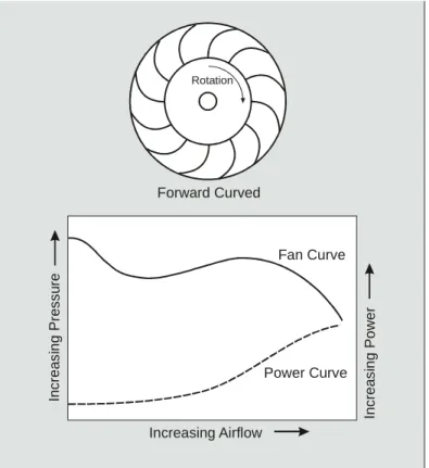
Forward curved (See Fig. 2)
- blades curve in the direction of rotation - compared to other types, have low efficiency (between 55 and 65 percent) - small size relative to other fan types - low speed, does not require high-strength design
- relatively quiet
- limited to clean service applications - fan output is difficult to adjust accurately (note how the fan curve is somewhat horizontal), and these fans are not used where airflow must be closely controlled. - the power curve increases steadily with airflow as the back-pressure drops
- applications that require low to medium air volumes at low pressure
- well suited for residential heating, ventilation and air conditioning (HVAC) applications
- careful driver selection is required to avoid overloading the fan motor.
- the dip in the performance curve represents a potential stall region that can create operating problems at low airflow rates.
Radial-blade, (See Fig. 3)
- suitable for low to medium airflow rates at high pressures
- capable of handling high-particulate airstreams, including dust, wood chips and metal scrap because the flat blade shape limits material build-up
- blades can be coated with protective compounds to add resistance to erosion and corrosion
- even in stall situations where vibrations can be a problem, large clearances between the blades also allow this fan to operate safely and quietly
- many rugged industrial applications
16
Type Characteristics Applications
Radial-tip, (See Fig. 3)
- fills the gap between clean-air fans and the more rugged radial-blade fans. This type is more efficient than forward curved and radial blade fans because of reduced turbulence resulting from the low angle of attack between the blades and the incoming air.
- well-suited for use with airstreams that have small particulates at moderate concentrations and airstreams with high moisture content
- efficiencies up to 75 percent
used in airborne solids -handling services because they have large running clearances.
Backward-inclined, flat
(See Fig. 4)
- flat blades are inclined in the direction opposite to the rotation
- considered more robust than other types - the low angle of contact with the airstream facilitates the accumulation of deposits on the fan blades
- performance drops off at high airflow rates
- suitable for forced-draft service. (Fan is exposed to the relatively clean airstream on the upstream side of the process.)
- unsuitable for airstreams with airborne particulates. - “safe” choice because of its non-overloading motor characteristic
- often selected when system behavior at high airflow rates is uncertain
Backward-inclined, curved (See Fig. 4)
- curved blades inclined away from the direction of rotation
- more efficient than flat blades - low angle of contact with the airstream promotes the accumulation of deposits on the fan blades
- performance drops off at high airflow rates
- suitable for forced-draft service. (Fan is exposed to the relatively clean airstream on the upstream side of the process)
- because of its non-overloading motor characteristic, this fan type is often selected when system behavior at high airflow rates is uncertain
17 Type Characteristics Applications
Backward-inclined, airfoil (See Fig. 4)
- airfoil blades tilt away from the direction of rotation
- most efficient with thin blades (~85%), but most unstable because of stall - low angle of impingement with the airstream promotes the accumulation of deposits on the fan blades as well as erosion.
- performance drops off at high airflow rates
- suitable for forced-draft service. (Fan is exposed to the relatively clean airstream on the upstream side of the process.)
- because of its non-overloading motor characteristic, this fan type is often selected when system behavior at high airflow rates is uncertain
Radial blade centrifugal fans are capable of serving widely varying operating conditions, which can be a significant advantage in industry.
Figure 2: Forward-Curved Centrifugal Fan Rotation Forward Curved Power Curve Fan Curve Increasing Airflow In c re a s in g P re s s u re Inc re a s in g P o w e r 18
Figure 3: Radial-Blade and Radial-Tip Centrifugal Fans Power Curve Fan Curve Increasing Airflow In c re a s in g P re s s u re In c re a s in g P o w e r Radial-Tip Rotation Rotation Radial-Blade 19
Figure 4: Backward-Inclined Centrifugal Fans 20 Power Curve Fan Curve Increasing Airflow In c re a s in g P re s s u re In c re a s in g P o w e r Backward-Inclined Flat-Blade
Rotation Rotation Rotation
Backward-Inclined Curved-Blade
Backward-Inclined Airfoil-Blade
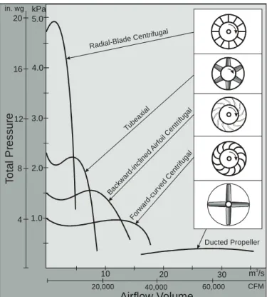
Figure 5 shows a comparative diagram of various fan
characteristics including the relationship between pressure and flow.
Figure 5: Comparative Fan Designs at an Equal Power Consumption Tube axia l Radial-Blad e Centrifugal Ducted Propeller Bac kwar d-in clin ed A irfoi l Cen trifu gal Forw ar d-curv ed C entri fuga l 10 20 30 m /s3 60,000 40,000 20,000 CFM Airflow Volume T o ta l P re s s u re 1.0 2.0 3.0 4.0 5.0 kPa in. wg 4 8 12 16 20 21
22 •
b.
Axial Fans
Axial airflow fans have a number of advantages over other types including:
• Compactness;
• Light weight;
• Low cost;
• Direct-drive units operating near the synchronous speed of the induction motor; and
• Belt-drive units offering flexibility in fan speed selection.
Usual applications for axial fans are:
• Exhausting contaminated air or supplying fresh air;
• Unidirectional or reversible air-flow applications; Exhaust applications where airborne particulate size is small, such as dust streams, smoke and steam.
Disadvantages
• Axial fans have an undesirable characteristic that can cause problems in situations where the air flow must vary considerably; these fans have a stall region in the lower airflow range that makes them unsuitable for systems operating under widely varying air flow conditions.
• There are anti-stall devices available that can be installed to alter the airflow patterns around the fan blades and virtually eliminate the problem of stall.
23
• The problem of stall can be avoided by selecting a fan type with a stable fan operation over the entire range of airflow and pressure.
• To achieve the same airflow capacity as centrifugal fans, axial fans must rotate at a higher speed. For this reason, axial fans are generally noisier than
comparable centrifugal fans.
• Access to the motor is restricted by the location of the blades and supports.
There are three types of axial fans; their characteristics and common applications are described in more detail in Figure 6.
24
Figure 6: Types of Axial Fans
Type Characteristics Applications
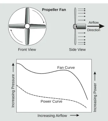
Propeller Fans (see Fig 7)
- develop high airflow rates and low pressures - not suitable for extensive ductwork - relatively low efficiencies - inexpensive - comparatively noisy
- power requirements of propeller fans decrease with increasing airflow
- maximum efficiency at lowest delivery pressure
- often used in rooftop ventilation applications
Tubeaxial Fans (see Fig 8)
- achieve higher pressures and better operating efficiencies than propeller fans
- applied in medium-pressure, high air flow rate applications - the airflow downstream of the fan is uneven, with a large rotational component
- generates moderate airflow noise
- because of low rotating mass, they can quickly accelerate to rated speed
- because of the high operating speeds of 2-, 4-, and 6-pole induction motors, most tubeaxial fans use belt drives to achieve fan speeds below 1,100 revolutions per minute
- well-suited for ducted HVAC installations - ventilation applications
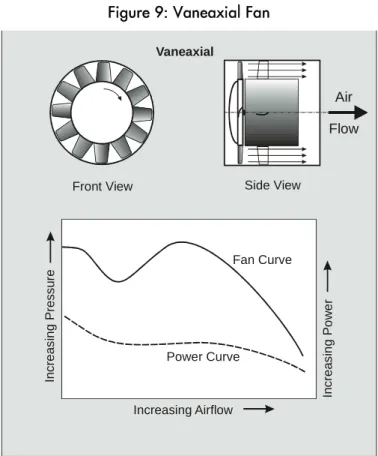
Vaneaxial Fans (see Fig 9)
- a vaneaxial fan is essentially a tubeaxial fan with outlet vanes to straighten the airflow, converting the airstream’s kinetic energy to static pressure
- the airflow profile is uniform
- when equipped with variable pitch blades, can be adjusted to change the angle of attack to the incoming air stream and air delivery rate
- have unstable regions to the left of the peak pressure - highly efficient: when equipped with airfoil blades and built with small clearances, efficiencies up to 85 percent are achievable
- usually directly attached to the motor shaft
- typically used in medium- to high-pressure applications, such as induced draft service for a boiler exhaust - low rotating mass, which allows them to achieve operating speed relatively quickly - emergency ventilation - reversal of air flow direction
The performance curve for propeller fans is shown in Figure 7.
Figure 7: Propeller Fan
Rotation Power Curve Fan Curve Increasing Airflow In c re a s in g P re s s u re In c re a s in g P o w e r Propeller Fan
Front View Side View
Airflow Direction
The performance curve for tubeaxial fans is shown in Figure 8.
Figure 8: Tubeaxial Fan
Power Curve Fan Curve Increasing Airflow In c re a s in g P re s s u re In c re a s in g P o w e r Tubeaxial
Front View Side View
Air Flow
Vaneaxial fans, a refinement over the axial fan involving flow straightening vanes, have a characteristic curve as shown in Figure 9
.
Figure 9: Vaneaxial Fan
Power Curve Fan Curve Increasing Airflow In c re a s in g P re s s u re In c re a s in g P o w e r Vaneaxial
Front View Side View
Air Flow
27
All three types of axial fans exhibit the stalling characteristic (where the pressure drops as the flow increases to the left of the peak pressure region) so care must be exercised in their application.
28
c.
Special Fan Designs
Bifurcated Fans
• In industrial processes that require the extraction of sticky, corrosive or volatile fumes, specially designed direct drive axial fans can be used.
• The motor of the axial fan is equipped with a unique protective casing that allows the motor to be removed from the airstream while maintaining a direct-drive arrangement. The casing protection is normally made from plastic or coated metal.
• The mating flanges at each end of the casing are identical. The casing diameter however is increased in barrel fashion around the casing to permit smooth passage of a similar cross-section of air concentric with the motor enclosure.
Centrifugal Inline Fans
Centrifugal fans are used in commercial applications where high efficiency, low sound levels and space are the main considerations.
• They have a direct-drive or belt-driven airfoil or backward inclined impellers, mounted perpendicular in a rectangular or tubular casing with ample clearance around the blade tips.
29
• The air is discharged radially from the blade tips and must turn 90 degrees to pass through the fan exit, which is in line with the impeller inlet. This fan produces what is called ‘‘mixed flow.’’
Centrifugal Roof Exhausters
• These specialized fans are designed as a package together with their housing. They are designed to exhaust air to the outdoors.
• The down-discharge configuration is used for exhausting relatively clean air. The up-blast configuration is used for exhausting hot or contaminated air.
• They are usually direct-driven or belt-driven airfoil or backward inclined impellers in a multi-component housing.
• The housing is comprised of a curb cap with an integral inlet venturi, a shroud with drive-mounting support and a weatherproof motor hood.
• The impeller has an inlet cone that allows mixed flow through the impeller blade passages and air exits radially from the blade tips through a concentric discharge passage. The shroud redirects the air, either down or up.
30
Utility Fans
• Packaged utility fans, complete with the motor (direct or belt driven), are available for commercial and industrial ventilation applications requiring low to medium air volumes and pressures. These fans are usually equipped with forward curved or backwards inclined blades.
31
5
UNDERSTANDING THE THEORY
The overall system energy efficiency for an existing system can be expressed in terms of the specific fan power (SFP). The science of SFP evolved in Europe and is gaining acceptance in North America.
The SFP is defined as the installed motor power of all the fans in the air distribution system divided by the design air flow rate.
SFP is expressed in terms of kW per 1000 CFM or in kW per (m3/s):
• An efficient system has a low SFP of usually under 0.7 kW/1000 CFM [1.5 kW/(m3/s)];
• A medium efficiency system has an SFP in the range of 0.7 to 1.9 kW/1000 CFM [1.5 to 4.0 kW/(m3/s)]; and,
• A low efficiency system has an SFP above 1.9 kW/1000 CFM [4.0 kW/(m3/s)].
Although the original design of a ventilation system will determine to a large extent the specific fan power value (based on the selected fan and motor characteristics, loading, duct system configuration and design properties, vents, filters), the SFP will be determined by the actual operating conditions. The efficiency of operation can be increased by modifying the ductwork to reduce pressure drop, by proper selection and maintenance of filters, by selecting the most appropriate
fan-32
motor combination, by shutting down the fans when air flow is not required and by avoiding over-ventilation.
Using SFP can help identify opportunities to increase fan system efficiency.
a.
Principles of Operation
• Systems that require air flow are normally supplied by one or more fans of various types, driven by a motor.
• The motor rotates the fan which delivers air to the system as it develops a pressure in the ductwork (or air pathways) that causes the air to move through the system.
• Moving air in a streamline has energy due to the fact that it is moving and it is under pressure.
In terms of air movement, Bernoulli’s theorem states that static pressure plus velocity pressure as measured at a point upstream in the direction of airflow is equal to the static pressure plus velocity pressure as measured at a point downstream in the direction of airflow plus the friction and dynamic losses between the two measuring points.
• The motor imparts energy to the fan, which in turn transfers energy to the moving air.
• The duct system contains and transports the air. This process causes some losses in static pressure due to friction with the walls and changes in the direction of
flow (due to elbows and other fittings), as well as air losses through unintentional leaks.
b.
Fan Laws
Rotational Speed: Fan rotational speed is measured in revolutions per minute (RPM). Fan rotational speed affects fan performance, as shown by the following fan laws.
Airflow rates vary in direct proportion to the rotational speed of the fan: initial final initial final
RPM
RPM
Airflow
Airflow
=
×
Pressure built up by the fan varies as the square of the rotational speed of the fan:
33 2
⎟⎟
⎠
⎞
⎜⎜
⎝
⎛
×
=
initial final initial finalRPM
RPM
pressure
pressure
Power required by the fan varies with the cube power of the rotational speed of the fan:
3
⎟⎟
⎠
⎞
⎜⎜
⎝
⎛
×
=
initial final initial finalRPM
RPM
Power
Power
34
Care needs to be taken when using the fan laws to calculate the effects of changes in fan speed, since these laws apply to a specific density of gaseous medium. When fan speed changes are accompanied by significant changes in other parameters such as gas composition, moisture content and temperature, the fan laws will need to be adjusted accordingly to
compensate for the resulting change in medium density. Rotational speed must be considered concurrently with other issues, such as:
• Air stream density (pressure, temperature, moisture content, gas composition);
• Ambient noise;
• Mechanical strength of the fan; and,
• Variations in the fan load.
To avoid overloading the motor, some types of fans must be sized appropriately for the air flow rate and pressure
requirement. In particular, forward-curved blade centrifugal fans, which are capable of generating high airflow at relatively low speeds, can readily provide excessive airflow and pressure and overload the motor if operated at too high a speed for the application. Moreover, operating the fan below the required speed can cause insufficient air flow through the system. Air stream temperature has an important impact on fan-speed limits because of the effect of heat on the mechanical strength of most materials.
For high temperature applications, low speed fan types provide the advantage of lower forces on shafts, bearings and blades, all of which have lower yield strengths at these temperatures.
35 (Dynamic stresses on these components are proportional to the square of the rotational speed).
c.
Fan Characteristics
Fan Performance Curve
The fan performance curve expresses the power required over the range of airflow rates. Individual points on a fan
performance curve are determined by plotting the developed pressure against the air flow rates. This curve is essential in the design of the system, in the selection of the equipment and in the operation of the system.
The Fan Characteristics section describes the various types of fans available, along with their pressure-flow characteristics. When the actual air flow in a system cannot be predicted with some accuracy, or the air flow is expected to vary considerably, it is very important to select the type of fan, motor and control system that will prevent equipment overloads.
Fan Efficiency
Fan efficiency is defined as the ratio of power transferred to the airstream to the power delivered to the shaft of the fan.
• The power of the airflow stream is the product of the pressure and the flow, corrected for consistency of units.
The fan efficiency can be expressed in terms of total pressure
(Total Efficiency) or in terms of static pressure (Static Efficiency).
Total Efficiency is the ratio of power of the airflow stream (using total pressure) divided by power delivered to the fan shaft in consistent units, or
6362
×
×
=
bhp
airflow
pressure
Total
Efficiency
Total
Where:• Total Pressure is in inches of water (in. WG)
• Airflow is in cubic feet per minute (cfm)
• bhp is brake horsepower
• 6,362 is the unit consistency factor
Static Efficiency is the ratio of power of the airflow stream (using static pressure) divided by power delivered to the fan shaft in consistent units, or
36
6362
×
×
=
bhp
airflow
pressure
Static
Efficiency
Static
Where:• Static Pressure is in inches of water (in. WG)
• Airflow is in cubic feet per minute (cfm)
• bhp is brake horsepower
• 6,362 is the unit consistency factor
Since the two defined efficiencies are quite distinct and different from each other, one must be clear to identify the type of efficiency referred to when comparing performance values.
37
Best Efficiency Point
• The best efficiency point (BEP) is a point on the operating characteristics of the fan where a fan operates most efficiently and cost-effectively in terms of both energy use and cost of maintenance/
replacement.
• Operation of a fan near its BEP results in high efficiency and reduced wear and tear on the
equipment. Operation far away from the BEP results in lower fan efficiency, increased bearing loads and higher noise levels.
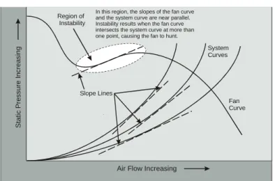
Region of Instability
• For most types of fans, the characteristic curve arcs downward to the right from the zero flow condition, indicating that as the backpressure on the fan is reduced, airflow increases.
• For all systems, the system resistance curve increases as the airflow increases.
• A fan operating in a typical system will normally settle at a pressure-flow point where the fan characteristic curve and the system resistance curve intersect.
• A fan operating in the region where the slope of the characteristic curve is in the same direction as the system curve can have unstable operation (see Figure 10), because of the fan’s interaction with the system: as the fan attempts to generate more airflow, the
system pressure increases, reducing the airflow. Then, as the airflow decreases, the system pressure also decreases, and the fan’s response is to generate more airflow. This cyclic behavior results in a cyclic increase and decrease in fan power requirement creating a reciprocating sound similar to ‘‘breathing.’’ This unstable operating condition results in reduced fan efficiency and increased wear on the fan components and may contribute to worker fatigue.
The following types of fans have an operating region in which their performance curve reverses direction so that it slopes in the same direction as the system resistance curve: tubeaxial, vaneaxial, propeller and forward-curved centrifugal fans. This creates a region of instability which should be avoided.
Figure 10: Fan Curve with Instability Zone
38
Region of Instability
In this region, the slopes of the fan curve and the system curve are near parallel. Instability results when the fan curve intersects the system curve at more than one point, causing the fan to hunt.
Slope Lines Fan Curve System Curves S ta ti c P re s s u re I n c re a s in g
39
d.
Control Systems
For many ventilation and air-moving requirements, it is necessary to be able to adjust the air flow from slight to
significant amounts. For these situations, there are several ways of providing the necessary control. While dampers that
increase pressure drop and reduce flow may be an inexpensive solution to implement on a system, they are not recommended because they represent the least efficient method of control, which results in an increase in power requirement and increased operating cost. More attractive options for controlling the air flow are:
• Motor controllers for motors with multiple speed windings that can be switched (e.g. 2, 4, or 6-pole devices) to make step changes in speed from full to 1/2 speed or 1/3 speed.
• Belt drives with various combinations of pulleys (sheaves) on the motor and the fan to vary the fan speed when driven by a single-speed motor.
• Variable pitch fan blades that can be adjusted to various angles of attack to change the amount of air flow at a nearly constant rotational speed.
• Adjustable speed drives for motors that change the speed of the fan from zero to greater than full motor speed in very small increments to provide the greatest amount of air flow variation.
40
Motor Controllers
An important component of the prime mover is the motor controller.
Motor controllers are switching mechanisms that receive a signal from a low power circuit, such as an on/off switch, low-medium-high/start selector switch, and are wired to relays that configure and energize the motor windings to drive the multiple speed motor at the selected speed.
Motors are built to operate at different speeds in two principal ways:
1. As a consequent pole motor: with a single set of windings equipped with a switch that energizes either a two pole configuration or a four pole configuration (to provide full speed and half speed as needed);
2. As a multiple speed motor: with the use of multiple windings and appropriate switching between 2- 4- 6- or 8- poles, to provide full-, half-, third- or quarter speed. Although multiple speed motors cost more and are less efficient than single-speed motors, they do provide effective and efficient speed and air flow control for many fan applications.
Belt Drives
A convenient way of reducing the rotational speed of fans (usually designed to operate under 1,800 rpm) is by making use of a belt drive between the motor and the fan using an
41 appropriate ratio of sheave to pulley diameter to achieve the
required fan speed reduction. The belt transfers the power from the motor to the fan, and changes the fan speed relative to the motor speed according to the desired pulley ratio. Since all the power from the motor is transferred to the fan entirely by the belt, the operating condition of the belt and its relationship with the sheave and pulley determine the efficiency and effectiveness of the power transfer and speed change. There are several types of belts, each one with its own set of advantages/disadvantages.
Types of Belt Drives
The four principal types of belts are:
• Flat belts;
• V-belts;
• Cogged V-belts; and,
• Synchronous belts.
The descriptions, advantages and disadvantages of each type are summarized in Figure 11.
Belt slippage reduces the fan rotational speed and causes an energy loss between the belt and the pulley, as well as reduced air delivery, and contributes to accelerated wear and
deterioration of the belt and pulleys
At the other extreme, over-tightening a fanbelt can result in early bearing (motor or fan) failure as well as early belt failure. When belt life becomes a frequent problem affecting the reliability of the system, it is necessary to review the factors outlined in the following sections that affect the operation and
42
life of the drive system: Belt Size, Fanbelt Maintenance Practices, Maximum Practical Speed Ratio for Fanbelts, Alignment of Pulleys, Variable Pitch Fan Blades and Adjustable Speed Drives.
Figure 11: Descriptions of Types of Drive Belts, Advantages and Disadvantages
Type Description Advantages Disadvantages
Flat - Uniform cross-section - Power transmission via friction contact with flat pulley surfaces
Simple, inexpensive Can slip easily
V-belts - Wedge cross-section - Wedging action on pulley supplements friction contact for improved power transfer
Reduced slip characteristic
Cogged V-belts
- Wedge cross-section - Notched belt adds belt flexibility
- Permits the use of smaller pulley diameters - Same advantages as V-belts
Slightly more efficient than conventional V-belts
Synchronous - Belts have teeth that engage with grooves in the sheave/pulley - Most efficient type of belt
- They do not contribute to loss of efficiency through slip - They tolerate lower belt tension than conventional belts - They reduce the radial load on motor and fan bearings and extending their operating lives - They maintain efficiency as they wear
- Very noisy - They transfer torque very quickly - Can cause problems in applications with rapid load changes - Although all belts should be properly aligned synchronous belts require more precise alignment than other belts
43
Belt Size
Four separate factors need to be considered in the selection of the belt size: the horsepower required by the driven load, the site operating temperature, the service factor and the actual arc of contact between the belt and the sheave or pulley.
The size of belt required is determined first by the horsepower being transmitted. However, because temperature also affects the mechanical strength of a belt, it is necessary to carefully size the belt to meet the highest torque required at the highest normal operating temperature. However, since rubber
contracts at higher temperatures, belts with high rubber content increase their tension and stress on bearings as the operating temperature increases.
The increase in stress of a belt drive during start-ups and changes in loads is often between 20 to 40 %. This increase in stress effectively increases the load on the belt drive and must be considered while sizing a belt. This increase, commonly known as the service factor, can vary between 1.2 to 1.4. Since belt drives rely on friction between the surface of the pulleys and the surface of the belt, the horsepower that can be transmitted by a belt-pulley combination (at a given tightness level) depends on the arc-of-contact with the smallest pulley. As shown in Figure 12 the horsepower rating of a V-belt declines as the arc-of-contact declines from 180° of the pulley circumference. At an arc-of-contact of 120°, the horsepower rating of a V-belt drive will decline by about 17% of its nominal rating. Different types of belt and pulley combinations will have different service factors.
Figure 12: Effect of Arc-of-Contact on V-belt Horsepower Rating
Degrees of Contact Correction Factor
180 1.00 170 0.98 160 0.95 150 0.92 140 0.89 130 0.86 120 0.83 110 0.79 100 0.74 90 0.69
Correction Factor for horsepower rating of V-Belts
Arc of Contact
The role of the belt is to deliver power to the fan. Since power to the fan is related to the cube of fan speed, a relatively small rise in fan speed can result in a significant increase in
transmitted power and stress on the belt, and vice-versa. For this reason, small changes in the slip speed of induction motors, or replacement of induction motors with (higher speed) synchronous motors, can have a significant effect on belt power requirements.
44
Although flow rate is linearly proportional to fan speed, the driving power required is proportional to the cube of the fan speed.
Establishing the right fan speed to operate the system efficiently determines the required belt power requirement. Underestimates of fan speed require reviews of the power rating requirement of the belt drive system
Many manufacturers recommend that fan-belt speeds should be kept below 6,500 feet per minute (ft/min.). This limit minimizes bearing loads, resulting in increased reliability.
45
Fanbelt Maintenance Practices
In order to maximize the reliability of fan systems, the following practices are recommended:
1. Checking belt tension and pulley alignment periodically. Belt drives should be tightened to the lowest level where the belt does not slip at peak load.
2. Avoiding the use of belt dressings (which are claimed to increase friction between the belt and pulley surfaces). Dressings mask and temporarily reduce the effects of belt slippage; a more permanent solution is to clean the drive system and adjust the belt tension to the proper level. 3. Some belts are often designed and tagged with a preferred
direction of rotation. Others can be operated in either direction; however, when manufacturers test these, they test in one direction and indicate this direction when packaged. To maximize belt life, install according to manufacturer’s directions.
4. Condition new belt drives for operation at high temperatures.
For belt drives that operate at high temperatures, it is recommended that new belts be operated at low load
conditions at the elevated temperature for a reasonable period of time to increase the creep strength of the belt material.
46 •
Maximum Practical Speed Ratio for Fanbelts
• Most industrial fanbelt drive applications are limited to speed ratios below 4:1 (the motor speed is 4 times faster that the fan speed). The reasoning is that for higher speed ratios, the area of contact between the belt and the sheave declines very quickly, reducing the amount of frictional force between the belt and the sheave. Increasing tension to overcome the lower friction is not an option because it adds too much mechanical stress to the bearings and to the belt itself. However, for small horsepower applications (less than 1 hp), this ratio can be as high as 10:1 because the forces involved are low enough and available friction between the sheave and belt is high enough to drive the fan without overstressing the belt and bearings. The limiting factors on speed ratios are the practical size of the pulleys, the arc of contact between the belt and the drive pulley, belt speed and force on the bearings.
Alignment of Pulleys
• All belts wear out in time, but proper belt installation (direction), alignment of pulleys (to minimize side wear) and proper tension ensure longevity and reliable service.
• Belt tightness can also be checked while running, by checking the slack side for excessive looseness on the slack side.
47
• Inadequate belt tightness shortens the life of the belt, promotes belt slippage (which reduces air flow) and can result in polishing the sheave surface, as well as wearing out the contact surface of the belt.
• A polished sheave surface has a lower than normal level of friction and reduces the belt’s ability to transfer power. As a consequence the air-delivery rate drops. As the belt wears it releases tension, further reducing the transmitted power and airflow rate.
Variable Pitch Fan Blades
• Processes that require changing airflow conditions can make use of variable pitch fans, which can efficiently change the amount of energy delivered to the air. Certain types of axial fans have a capability that allows the adjustment of the pitch of the blades. Operating at a constant speed, the variable pitch feature causes the angle of attack between the incoming air and the blade to change, as well as the power imparted to the air to vary from almost zero flow to full flow.
• Reducing the angle of attack of the fan blades reduces the rate of airflow, the load on the motor and the motor consumption over time.
• Although variable pitch fans cost more than fixed blade fans, they offer a very efficient operation. In addition, since variable pitch fans can be operated at a nearly constant speed, resonance problems can be avoided.
48
• A very important benefit of variable pitch fans for controlling air flow rates is that this type of fan does not experience a ‘‘stall’’ problem as the flow is varied from no-flow to full-flow conditions. A secondary benefit of this type of fan is that it can be started unloaded at very low torque to reduce the starting torque on the motor.
• Variable pitch blades have mechanical actuators that are exposed to the air stream and, depending on the application, they have the potential of fouling by the accumulation of contaminants.
• If a process requires partial or reduced air flows for a significant portion of the day, every day, the variable pitch fan may not be the best option, since motor efficiency drops and power factor increases for motor loads below 50 percent. Operating at low loads for long periods may not provide efficiency advantages and will result in a low power factor for the motor. It may actually be more economical in the long-run to consider multiple fans or other air flow rate control options.
Adjustable Speed Drives
• The operating speed of electric motors can be
controlled with adjustable speed drives (ASDs). These electronic or mechanical devices allow the user to adjust the speed of operation of motors efficiently and continuously from virtually zero to full speed.
49
• There are various types of electronic variable frequency drives available including ac and dc motor drives andwound rotor motors. These drives regulate the power flowing to the motor, thus there would not be a concern with regards to power factor penalties for operation at low motor power levels.
• There are various types of mechanical ASDs including adjustable belts and pulleys as mentioned earlier, hydraulic clutches, fluid couplings and eddy current clutches.
A fan driven by a motor controlled by an electronic adjustable speed drive operates efficiently over most of the speed range. The point of operation on the fan’s characteristic is unchanged as the speed varies and the duct pressure changes (as the square of air speed). This has the advantage of maintaining the fan’s efficiency, resulting in a corresponding maximum reduction in power consumption and fan noise level as the speed is reduced (see Figure 13).
Figure 13: Flow Control by Speed Regulation System Curve S ta ti c P re ss u re I n cr e a s in g
Air Flow Increasing
F a n P o w e r In cr e a si n g A = Full Speed B = 75% Full Speed C = 50% Full Speed A B C Power (F ull Spee d) Power (75% FS) Pressure (Full Speed)
Pressure (75% F S) Power (50% FS) Pressu re (50% FS) Design Working Point
Word of Caution:
50Tubeaxial, vaneaxial, propeller and forward-curved centrifugal fans may become unstable when operating over a speed range where the slope of the fan characteristic is parallel to the slope of the system curve and the intersection between both
characteristic curves becomes indeterminate, causing a cyclic loading and unloading which causes annoying noise and excessive wear.
Although ASDs offer one of the most efficient methods of controlling the performance of a fans one must be very careful about the type of fan being controlled, the relationship between the system curve and fan characteristic curve and the speed range of control.
51
e.
Energy Saving Checklist
The list of questions in Figure 14 can be used to identify potential opportunities for improving the efficiency of fan systems. Also listed are the approximate savings resulting from the implementation of each efficiency measure.
52
Figure 14: Energy-Saving Checklist for Fan Systems Area Question Improvement Typical
Energy Savings
Process Is the system doing useful work continuously or periodically?
Shut down when not required 10-50% Have the exact requirements for the
process been determined or re-evaluated for an older system?
Oversizing leads to inefficiency 10-50%
Location of Fan
Does the location of the fan minimize the system resistance?
Relocate the fan to reduce length of runs, straighten bends
5-30% Variation in
airflow demand
How is the supply of air to the system controlled and varied?
VSD, variable pitch axial fans, multi-speed motor
5-30%
Fan type and application
What type of fan is installed and is the impeller facing in the right direction?
Replace with an impeller with the required characteristics and facing in the right direction
depends
Is it a centrifugal fan producing too much or too little air flow?
Change the impeller to reduce/ increase the amount of air flow and optimize energy consumption
depends
Incorrect type of fan for required pressure/flow characteristics?
Savings can be achieved if a more efficient fan is available to provide a closer match to system demand
5-30% Fan Inlet Ductwork (See Ductwork section)
What are the entry conditions like? (Is there a swirl in the opposite direction to the fan blade at the inlet of an axial fan?)
An entry swirl in the opposite direction to fan rotation can cause a motor overload; Install fixed blades to straighten the flow
5-15%
Is there a sharp bend near the entry point of the air into the fan inlet?
Install turning vanes to even out the flow of air into the fan inlet
5-15% Is there a transition piece where duct
size is reduced or increased?
Install a transition piece 5-15% Are flexible connections fitted with
no offset or slack?
Inspect and adjust Up to 30% on low pressure axial fans
53 Area Question Improvement Typical
Energy Savings Fan outlet ductwork (See Ductwork section)
Are there bends in the ductwork near the fan outlet?
Try to avoid bends near the outlet. If unavoidable, use turning vanes to direct and distribute the air flow evenly
depends
For axial or propeller fans, is there a set of straightening guide vanes to recover pressure?
Guide vanes should be considered for pressures above 750 Pa (3-in WG)
depends
Motor Is the motor oversized? If loaded at or below 50% for extended periods, consider downsizing or installing multiple fans
5-10%
Is the motor operating on all 3 phases?
Check for faulty wiring and fuses 0-15% Is an ac motor running below normal
speed?
Problem can be with a winding or with the starter circuit
0-10% Is the motor a high efficiency type? Except for low duty motors, high
efficiency motors are economically worthwhile
2-5%
System ducting
What shape is the duct cross-section?
Tubular ducting (rather than rectangular) results in the least amount of material, lowest pressure drop, lowest velocity, and lowest losses
7%
System performance
If dampers are used for balancing, is the pressure as low as it can be?
Good design should ensure that all legs have equal pressure losses. Re-balance to minimize pressure drop
7%
Has a measurement of absorbed power (pressure-drop x velocity) been made?
This measurement can be used to detect changes in energy consumption on the air moving side of the system
6
SYSTEM & OPERATIONAL
CONSIDERATIONS
A fan system usually consists of a fan near the inlet or the outlet connected to a duct system. The duct system can have various components installed within the air pathway such as air control dampers, heat exchangers, filters on the inlets or outlets, diffusers and noise attenuators (see Figure 15). The fan drives the air stream to overcome resistance caused by the ductwork and other components. The ducting directs the air flow to the required locations and also acts as a support or housing for the other components used in the particular process.
Figure 15: A Fan within a System
Air Inlet F i l t e r H e a t e r Fan Outlet Diffuser Fan Balance or Control Damper
Ducting, Bends, etc.
Air Delivery to Ventilated Space 55
a.
System Curve
The system curve is defined as the static pressure versus flow rate characteristic curve for the entire system. The static
pressure is the sum of the individual pressure losses along the system attributed to each component such as:
• Ducts;
• Dampers;
• Baffles;
• Filters;
• Grills;
• Connections and diversions (tees, wyes, elbows);
• Louvers; and,
• Intrusions, obstacles, within the system.
The static pressure drop is proportional to air velocity squared. The equation that relates pressure drop across a component is:
ρ
×
⎟
⎠
⎞
⎜
⎝
⎛
×
=
Δ
21097
V
C
p
56 Where:Δp = pressure loss in inches of water gage (in. wg) C = loss coefficient for the component
V = velocity in feet per minute
ρ = density of the airstream (0.075 pounds per cubic foot at standard conditions)
When all the components are in series, the total system
pressure drop Δp is the sum of the individual pressure drops. If
Static Pressure Drop is plotted versus air Velocity, the resulting curve will be parabolic in shape, as shown in
Figure 16. This curve now represents the theoretical system
curve (based on the assumptions made about the pressure loss
57
series). In reality, however airflow is usually non-uniform because the airstream develops swirls, and vortices and uneven flow distributions caused by interference with system
components. The net result is that actual total pressure drops (losses) are higher than the theoretical loss would indicate. In effect, these added losses tilt the system curve up, as shown Figure 16. This tilt upwards of the system curve is called the
system effect. Systems that have a lot of obstacles, corners and
changes in directions tend to have a higher systems effect. Systems that are composed of straight, open paths are conducive to low (pressure drop) losses and a much lower system effect.
The condition at which the system operates is called the
balance point. The balance point corresponds to the
intersection of the system curve and the fan characteristic point, as shown on a plot of system pressure vs. flow in Figure 16. This figure plots the theoretical system curve and the modified system curve including the system effect. These two curves intersect the fan characteristic curve at two points: the theoretical balance point (A) and the actual balance point (B). By comparing the values of pressure and flow at each
intersection point, one notes that the expected performance according to the theoretical system curve (point A) is considerably different (lower pressure drop and higher flow rate) than the actual performance at point B (higher pressure and lower flow, requiring more fan power). Since it is difficult to accurately predict the magnitude of the system effect, system designers specify a certain amount of fan overcapacity to reduce the risk of not meeting the flow and pressure requirements of the process. However, over-design of fan systems results in having to adjust the flow to meet the system
requirements, and depending on how this is done, the adjustment can have a significant impact on energy consumption.
The system effect can be kept very small by configuring the system for as uniform and unidirectional flow as possible. By doing this, the fan selection would be closer to the theoretical requirement and overcapacity would be unnecessary.
Figure 16: System Effect for a Typical Fan and System
Fan Curve Flow Rate (CFM) S ta ti c P re s s u re ( in . W G ) 2,000 6,000 10,000 14,000 18,000 2 6 10 14 18 22 System Curve (as calculated) System Curve (with system effect)
Actual Performance Expected Performance A B 58
Since the operation of a fan is affected by system components, it is necessary to look at the entire system in order to optimize the operation of a fan and reduce its energy consumption. This is called the ‘‘systems approach.’’
59
b.
Systems Approach
The systems approach looks at the operation of the entire system by considering the characteristics of each component as well as the interactions among the components over all operating conditions. The factors and considerations to be taken into account when selecting a fan and/or fan system that is efficient both in terms of its performance and its energy consumption include:
1. Selecting the most appropriate fan for a particular application.
2. Selecting the correct type and rating of the motor used to drive the fan.
3. Control systems for fans, and the factors that need to be taken into account when deciding which type to use. 4. Determining the air velocity as part of the design process. 5. Minimizing pressure drop through the entire system. 6. Correct installation in terms of fan inlet and outlet
conditions and mounting.
7. Regular maintenance of the fan and fan system. 8. Conducting an annual system review to ensure that the
maximum energy savings are maintained.
Striking the right balance between these competing costs requires effort; however, using a systems approach during the design phase can minimize system life-cycle costs.
60 2.
These factors are described in more detail below:
1. The efficiency curve of fans is far from constant and there can be a difference of 30% between peak and low
efficiency in the fan’s working range. In addition, the energy use of similar fans from different manufacturers performing the same duty can vary by up to 30%. It is therefore important to select a fan that is operating as near its peak efficiency as possible in the normal operating range. Fan specifications should stipulate the use of a high efficiency fan.
Select high efficiency rather than standard efficiency motors to achieve maximum energy savings during the operational life of the equipment (these can save, on average, 3% of energy consumption compared to standard motors). Sizing the motor correctly is also very important, as it can significantly reduce both the capital and running costs of electric motors. Motors are often rated well above the power levels at which they operate. Modern motors are designed for maximum efficiency at 75% of full load, although there is minimal variation in efficiency between 50% and 100% load. Significant reductions in efficiency occur at 25% load or less. Oversized, under-loaded motors operate at lower efficiency levels, and may contribute towards the need to add power factor correction capacitors.
3. Most systems require some type of air flow rate
adjustment. The rate may be required to be adjusted once only to compensate for initial errors in calculation, intermittently to give, for example, a summer and winter condition, or continuously to maintain an environment or
61 to supply a variable process. Control can be achieved either by changing the effective resistance of the system or by altering the performance characteristic of the fan. The method chosen will strike some balance between savings in absorbed (wasted) power at reduced flow rates and the initial cost of the flow control method used.
Although dampers offer the simplest means of adjusting air flow, closing the damper increases the resistance to flow and the quantity of air falls as determined by the fan characteristic. The pressure loss across a damper is a waste of energy may create noise and should be avoided. A more efficient method of controlling air flow rate is to adjust the performance of the fan itself by changing the fan speed or by other means as described in the Control Systems Section.
4. Air velocity is the first choice to be made when designing a fan system. Low velocity systems should be used where possible, because they produce low pressure losses and require the lowest fan power level, thus minimizing energy use. However, this also means designing ductwork with the largest cross-sectional area, requiring more materials and space.
5. While minimizing pressure drop through the entire system will automatically reduce the energy requirements to operate the system, for practical reasons such as limited space, smaller duct systems may have to be selected, implying higher air velocities and pressure drops. The advantages and disadvantages of low, medium and high velocity systems are outlined in Figure 17.
62
Figure 17: Advantages & Disadvantages of Low, Medium & High-velocity Systems
System Velocity
Advantages Disadvantages
Typical filter & coil face velocities (m/s)
Typical main duct velocity (m/s)
Low <2 5 Low fan power
Low noise
Higher capital cost More space Medium 2-3 8 Lower capital cost
Requires less space
More fan power Increased noise High >3 ≥12 Least capital cost
Least space
High fan power High noise
6. The fan inlet and outlet conditions and mounting can have a significant effect on system performance. The three most common causes of poor fan performance due to
installation effects are: non-uniform inlet velocity, swirl at the inlet and improper outlet conditions such as uneven airflow distribution and immediate change in direction. In each case, the performance of the fan is hampered by the inlet and outlet conditions, causing a shortfall in delivery capacity compared to the published level. Because the magnitude of this effect is often unknown, contingencies may have to be added to the calculated system curve to allow for shortfall in fan performance due to the inlet and outlet conditions. This can result in increased capital and running costs, and a system that is not operating at its designed condition. The fan inlet and outlet conditions can be improved by preventing sharp bends in the
ductwork in both the inlet and outlet, using turning vanes or flow straightening vanes as required to prevent
63 recirculating flow and counter rotating flow at the inlet
and non-uniformity in the outgoing air flow stream. 7. Regular maintenance of the fan and fan system is essential
to ensure it continues to operate at maximum efficiency and hence minimum energy use. Maintenance items include: checking fastenings on the fan and motor, checking impeller, balance, flexible connections to the ductwork, shaft bearings (lubricate or replace), sheaves and pulleys, belts, filters and other elements (check, replace). 8. An annual system review of the performance of the system
will ensure that the maximum energy savings are
maintained. The system performance should be checked to ensure that it meets the current production requirements and ties in well with the results of the original
commissioning. If the system is not meeting requirements, it is prudent to investigate and identify the cause(s). Examples of changes that can be considered for improving performance by changing air flow rate include:
o Changing the pitch angle of an axial impeller; o Changing the pulley ratios on a belt drive; o Changing the impeller to increase or decrease
the volume flow within the limitations of the existing motor power (only in extreme cases); and,
o Contacting the original equipment supplier for technical advice.
The following sections present more details on the adjustments and alterations that can be made to system components to adjust and improve the overall system performance.
64
Type of Fan and Effect of Blade Angle Change
• Once a system is operational and its use patternestablished, a comparison of pressure-flow system requirements and fan characteristics can be made to determine whether the fan is operating according to expectations and specifications (remember to take into account the system effect).
• If adjustments need to be made because of mismatch between fan characteristics and system requirements, a different type of fan or a different angle blade can be considered.
• Failing this, other options include a different drive speed (sheave and pulley ratio) or different type of drive system such as a variable frequency drive if wide changes in air flows are also required.
Effect of Belt Condition
Belt drives are frequently the most maintenance intensive component of a fan motor assembly, and typical factors include:
• Belt wear;
• Noise;
• Rupture;
• Belt tension;
• Uneven belt tension;
• Contaminants buildup on the belt;
• Slippage;
65
• Misalignment.
Over-tightening belts can result in the shortened life of the belt itself as well as the bearings and, in extreme cases, structural problems with the motor-fan assembly.
Loose belts result in wear and polishing of the of the sheave and pulley running surfaces, encouraging more slippage and belt wear, as well as heating of the belt and reduced air flow.
Process Equipment Cleaning Economics
Air-moving systems include components that interact with and impede the flow of air such as heat exchangers used to
condition the airstream to achieve a particular temperature or to remove moisture, filters (cyclone types or mesh types) to remove unwanted particles or gases and flow diverters that inherently create pressure drops, adding to the overall pressure drop of the system.
• Mesh-type filters create increasingly large pressure drops as they accumulate particles. In many systems, poor performance and increased operating cost are a direct result of inadequate attention to filter
cleanliness.
• Regular filter inspection and maintenance should be a priority item.
• Simple instrumentation or alarms can be installed to monitor pressure drops across heat exchangers and filters to warn of fouling and to optimize the