Micropower energy harvesting
R.J.M. Vullers
a,*, R. van Schaijk
a, I. Doms
b, C. Van Hoof
a,b, R. Mertens
b aIMEC/Holst Centre, High Tech Campus 31, 5656 AE Eindhoven, The Netherlands b
IMEC, Kapeldreef 75, 3001 Leuven, Belgium
a r t i c l e
i n f o
Article history:Received 17 November 2008 Accepted 22 December 2008 Available online 25 April 2009
The review of this paper was arranged by Prof. P. Ashburn Keywords: Energy harvesting Micromachining Power management Micropower
a b s t r a c t
More than a decade of research in the field of thermal, motion, vibration and electromagnetic radiation energy harvesting has yielded increasing power output and smaller embodiments. Power management circuits for rectification and DC–DC conversion are becoming able to efficiently convert the power from these energy harvesters. This paper summarizes recent energy harvesting results and their power man-agement circuits.
Ó2009 Elsevier Ltd. All rights reserved.
1. Introduction
The low power consumption of silicon-based electronics has en-abled a broad variety of battery-powered handheld, wearable and even implantable devices. A range of wireless devices spanning six orders of magnitude power consumption are shown inTable 1, with their typical autonomy.
All these devices need a compact, low-cost and lightweight en-ergy source, which enables the desired portability and enen-ergy autonomy. Today batteries represent the dominant energy source for the devices inTable 1and alike. In spite of the fact that energy density of batteries has increased by a factor of 3 over the past 15 years, in many cases their presence has a large impact, or even dominate, size and operational cost. For this reason alternative solutions to batteries are the subjects of worldwide extended investigations. One possibility is to replace them with energy stor-age systems featuring larger energy density, e.g., miniaturized fuel cells[1]. A second possibility consists in providing the energy nec-essary to the device in a wireless mode; this solution, already used for RFID tag, can be extended to more power hungry devices, but it requires dedicated transmission infrastructures. A third possibility is harvesting energy from the ambient by using for example, vibra-tion/motion energy, thermal energy, light or RF radiation.Table 2
summarizes the output power that could be obtained from envi-ronmental sources when using optimized devices built with the currently available transducer technology. For each type of sources,
different ambient situation are considered. They correspond to var-ious level of available power, and hence of generated electrical power. We notice that outdoor-light outperforms all other energy sources, but indoor-light is fairly comparable to thermal and vibra-tion energy. We also notice that while industrial environments seem to have energy to spare, around the body energy is far more limited.
Table 2suggests that energy harvesters can be used effectively in the 10
l
W to 1 mW range, which is typical of wireless sensor nodes. A sensor node is a device made of (i) a sensor which will capture the required physical or chemical parameters, (ii) of an ADC and signal processor module which will be used for trans-forming the measurements into useful (digital) information, and (iii) of a radio module which will allow communication with exter-nal portable devices.The power consumption of a sensor node has been estimated by various authors, recent works[2,3] quote values between 1 and 20
l
W. Consumption strongly depends on the complexity of the sensed quantity and on the number of times per second it has to be transmitted. Practical implementation of a sensor node show that 90l
W is enough to power a pulse oxymeter sensor, to process data and to transmit them at intervals of 15 s [4]. The value of 100l
W reported in Table 1 is therefore representative of relatively complex nodes, for systems operating at relative high data-rate.Wireless sensor networks are made of large numbers of small, low-cost sensor nodes working in collaboration to collect data and transmit them to a base station via a wireless network. They are finding growing application in body area networks and health
0038-1101/$ - see front matterÓ2009 Elsevier Ltd. All rights reserved. doi:10.1016/j.sse.2008.12.011
*Corresponding author.
E-mail address:[email protected](R.J.M. Vullers).
Contents lists available atScienceDirect
Solid-State Electronics
monitoring of machine, industrial and civil structures. These net-works are intended in many cases to operate for a period of years. Because of the large numbers of devices and of their small size, changing the battery is unpractical or simply not feasible. Increas-ing the size of the battery to ensure energy autonomy durIncreas-ing the lifetime of the system would increase system size and cost beyond what is tolerable. The combination of an energy harvester with a small-sized rechargeable battery (or with another energy storage system like a thin-film rechargeable battery or a super capacitor) is the best approach to enable energy autonomy of the network over the entire lifetime.
InFig. 1a comparison is made for several energy storage sys-tems. A volume of 1 cm3is assumed. If the power consumption of the sensor node is approximately 100
l
W, the lifetime of a pri-mary battery is only a few months. The combination of a recharge-able battery and an energy harvester with a power generation of 100l
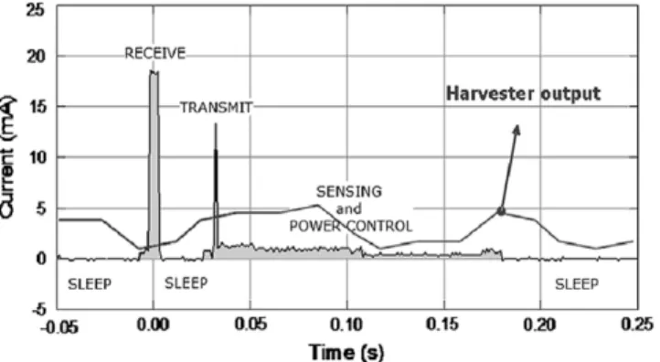
W is shown for comparison. In such case the harvester en-sures power for the whole lifetime.Abolishing the energy storage system altogether is not an op-tion in most cases. In practice, a wireless sensor node needs a wire-less transceiver. The peak currents needed during transmit and receive operation go beyond what is achievable using the harvester alone (seeFig. 2). Furthermore, buffering is also needed to ensure continuous operation during times without power generation. Depending on the application, the energy storage system can be a battery or a supercapacitor.
Most promising batteries are based on Li-ion-polymer and were first developed in 1997. Recently thin film and microelectronics integration technology has been utilized to fabricate thin film bat-teries. Unlike conventional batteries, thin film batteries can be integrated directly in Integrated Circuit (IC) packages in any shape or size, and when fabricated on thin plastics, some are flexible. One important drawback of this technology is higher impedance values when compared to Li-ion. As a result, the discharge efficiency[5,6]
Fig. 1.Comparison of lifetime versus power consumption for several energy storage systems (1 cm3
), including one with an energy harvester.
Fig. 2.A typical scenario for the power consumption of a sensor node. Since the consumption does not equally match the harvester output, an energy buffer and power management IC in between is necessary.
Table 3
Characteristics of batteries and supercapacitors.
Battery Supercapacitor
Li-ion Thin filma
Operating voltage (V) 3–3.70 3.70 1.25
Energy density (W h/l) 435 <50 6
Specific energy (W h/kg) 211 <1 1.5
Self-discharge rate (%/month) at 20°C 0.1–1 0.1–1 100
Cycle life (cycles) 2000 >1000 >10,000
Temperature range (°C) 20/50 20/+70 40/+65
a
Data calculated including the packaging.
Table 1
Selected battery-operated systems. Device type
Power consumption Energy autonomy
Smartphone 1 W 5 h
MP3 player 50 mW 15 h
Hearing aid 1 mW 5 days
Wireless sensor node 100lW Lifetime
Cardiac pacemaker 50lW 7 years
Quartz watch 5lW 5 years
Table 2
Characteristics of various energy sources available in the ambient and harvested power.
Source Source power Harvested power
Ambient light Indoor 0.1 mW/cm2 10lW/cm2 Outdoor 100 mW/cm2 10 mW/cm2 Vibration/motion Human 0.5 m @ 1 Hz 1 m/s2@ 50 Hz 4lW/cm2 Industrial 1 m @ 5 Hz 10 m/s2@ 1 kHz 100lW/cm2 Thermal energy Human 20 mW/cm2 30lW/cm2 Industrial 100 mW/cm2 1–10 mW/cm2 RF Cell phone 0.3lW/cm2 0.1lW/cm2
of this battery will be lower when compared to that of a Li-ion bat-tery with liquid electrolyte material.
Supercapacitors bridge the gap between batteries and con-ventional capacitors. This technology is especially suited for applications where a large amount of power is often needed for fractions of a second to several minutes.
The main characteristics of the batteries and supercapacitors are illustrated inTable 3. The characteristics calculated for the bat-teries and supercapacitors are based on measurements carried out with in-house equipment and the best-known storage systems. It follows from Table 3 that battery and supercapacitors differ strongly on the main parameters. Therefore, the choice between the two systems for use as a buffer really depends on the require-ments of the envisioned sensor node application.
In the following sections we will focus on emerging methods for power generation through energy harvesting and on power management.
2. Energy harvesting approaches
2.1. Harvesting energy from motion and vibration
For converting motion or vibration, the established transduc-tion mechanisms are electrostatic, piezoelectric or electromag-netic. In electrostatic transducers, the distance or overlap of two electrodes of a polarized capacitor changes due to the movement or to the vibration of one movable electrode. This motion causes a voltage change across the capacitor and results in a current flow in an external circuit. In piezoelectric transducers, vibrations or movement cause the deformation of a piezoelectric capacitor thereby generating a voltage. In electromagnetic transducers, the relative motion of a magnetic mass with respect to a coil causes a change in the magnetic flux. This generates an AC voltage across the coil.
If the energy source is a slow, long-stroke movement, it may be possible to anchor one of the two parts of the transducer to a fixed reference and the other to the source of movement[7]. In most cases however, this is not possible and the principle of inertia has to be used: the transducer is inserted in a frame, one part of it is fixed to the frame itself, and the other can move. The frame is attached to the moving or vibrating object and relative motion of the parts of the transducer is controlled by the law of inertia. This approach is the most widely used for harvesting energy from vibrations[8]; in most cases the system is made resonant by means of suspending the moveable part to a spring. It can also be used for motion energy harvesters[9,10]in which case no spring is used and a non-resonant system is the result.
Resonant vibration harvesters are by far the most widely inves-tigated in the literature. Fine-machined versions are the earliest emerging commercial devices while micromachined versions on the other hand are far less mature. Their power levels need to be
raised, reliability needs to be achieved, and cost-effective produc-tion has to be established.
In a first and rather crude approximation, resonant harvesters can be treated as a velocity damped mass spring system, described by the following differential equation:
m€zþ ðdþdgÞz_þkz¼m€y ð1Þ zrepresent the motion of the mass, dgthe damping due to the
trans-fer of mechanical energy to the electrical load,dthe one due to par-asitic effects, e.g. presence of air, friction of sliding surfaces and similar,kthe spring constant of the suspension,mthe moving mass andy the amplitude of the frame movement in z direction (see
Fig. 3).
The power dissipated in the damperdgis a pronounced function
of frequency. If the input is sinusoidal the maximum power is ob-tained when the input frequency is equal to the resonance fre-quency of the system and is given by[11]
Pres¼
mxresfgjY_j 2 4ðfþfgÞ
2
where f= d/2m
x
and fg= dg/2mx
are non-dimensional dampingfactors andYis the amplitude of the input vibration. It can be seen that the maximum power is obtained when generator and parasitic damping are equal. Also it is clear that the lowest possible damping should be used in order to maximize power. This strategy is limited by the fact that when damping decreases the oscillation amplitude also increases, but it cannot go beyond the physical dimensions of the system.
It has been shown[8]that ifzmaxis the maximum possible
dis-placement, the corresponding power is obtained for a well defined value of the damping and is given by(2)
Pres¼4
p
3mf 3resYzmax ð2Þ
wherefresis the resonance frequency. Harvester performances are
frequently benchmarked against this value of the power[3]. It is also shown that the same maximum power can be obtained from non-resonant systems having the same physical characteris-tics[11]. In principle this optimum power can be achieved with any type of transducer[12]. Depending on the transducer type, it is delivered at different voltages. With typically available vibra-tions, the output voltage tends to be too low in the case of electro-magnetic transducers and too high for electrostatic transducers. These conclusions are derived from the approximated analysis gi-ven in[11], thus being not universally valid, they indicate the gen-eral behavior of the vibration harvester. More accurate analysis can be found in the literature[13,19]. It is not possible in this short re-view to mention and describe all the devices reported in literature; we will limit ourselves to some relevant results.
Let consider micromachined harvesters. From a process per-spective, the electrostatic and piezoelectric harvesters are easy to fabricate and devices with lateral sizes between 1 and 10 mm have been reported in literature. Most electromagnetic harvesters
on the other hand have been fabricated using a combination of micromachining and mechanical tooling techniques (macroscopic fabrication) because the creation of coils with sufficient windings is not compatible with planar microfabrication. As a consequence the electromagnetic energy harvesting devices are large and there-fore also generate more power. Representative devices are shown inFigs. 4–6, for electrostatic, piezoelectric and electromagnetic en-ergy harvesters, respectively, and results can be found in[13–23]. Electrostatic harvesters evolved from the initially reported 12 nW for a 2 mm3device[13], to 2.4
l
W for a 3 cm2device[15]and more recently 12
l
W for a 1 cm2device[16]. Piezoelectrichar-vesters achieved 3
l
W[17], 40l
W[19]measured on a PZT based harvester and 2l
W [18], and 60l
W [23] on an AlN based harvester. A comparison is not obvious as the sizes, resonance fre-quencies and vibration conditions are different. A completely micromachined electromagnetic energy harvester has been pre-sented in[14], but it generated only 150 nW when excited by an acceleration of 0.4 g at 8 kHz. Macroscopic electromagnetic har-vesters have achieved 17.8l
W at 60 Hz (size 150 mm3) [24], 37l
W at 322 Hz (0.84 cm3) [25] and 830l
W at 85 Hz(7.30 cm3), 2.5 mW at 102 Hz[26].
Currently there are large vibration harvesters on the market, typically 100–200 cm3, delivering tens of mW’s of power at around
50–120 Hz (e.g. Perpetuum[21]and Ferro solutions[27]).
How-ever, due to their size and fabrication method, these are expensive systems, used for niche applications (e.g. army, remote plants). Application in mass-market systems will only be achieved when micromachined devices become available.
2.2. Harvesting energy from temperature differences
Thermal energy harvesters are based on the Seebeck effect: when two junctions, made of two dissimilar conductors, are kept at a different temperature an open circuit voltage develops be-tween them.
Fig. 7, left shows the schematics of a thermocouple, the simplest voltage generator based on the Seebeck effect. We distinguish two pillars, or legs, made of two different materials and a metallic interconnect. When a temperature differenceDTis established be-tween the bottom and the top of the pillars a voltageVdevelops between the points A and B. This voltage is given by
V¼
a
1DT
a
2DT
where
a
1anda
2are material dependent quantities, known asSee-beck coefficients. Typically semiconductors are used as pillars, as their Seebeck coefficient is large. Furthermore the sign of the See-beck coefficient is opposite forp-type andn-type semiconductors, so that the contribution of the two pillars to the voltage adds up if semiconductors of opposite doping are used.
The core element of a thermal energy harvester is the thermo-pile, i.e. a device formed by a large number of thermocouples placed between a hot and a cold plate and connected thermally in parallel and electrically in series (seeFig. 7, right). Besides the thermopile the generator may include (i) a radiator for efficient dissipation of heat in the ambient and (ii) specific structures (ther-mal shunts[28]) aimed to direct the heat passing between the hot and cold plate into the thermocouple legs.
The thermopile and the additional elements described above are inserted in a simple thermal circuit, schematically shown in
Fig. 8. As an illustrative example of the components inFig. 8, we consider a generator placed on the human body. Then the
temper-Fig. 5.Example piezoelectric energy harvesters from[18,23].
Fig. 6.Example electromagnetic energy harvesters from[22,10].
Material 2 Metal interconnect
T
hotT
coldT
hotT
cold Material 1 A B Load Load Loadature of the source would be the core temperature of the body, i.e. 37°C, the one of the sink the temperature of the air. The thermal resistance of the source would be the one of the body and the ther-mal resistance of the sink represents the limiting factors in the heat exchange between the thermopile and the air. In order to optimize the thermoelectric generator it is necessary to properly design the thermopiles and the other constitutive parts described above. As for the thermopile appropriate dimensions and number of the legs have to be determined. In the optimization process the resistance of the thermopiles varies, and action can be taken to modify also those of the sink and the source. It is anyhow interesting to pro-ceed to the optimization assuming that the heat flow through the thermopile is constant. This approximation, almost valid if the thermal resistance of the sink and the source are very large, al-lows to perform simple calculations and to have some insight in the problem. A complete treatment of the optimization strategy can be found in[29].
If a certain amount of heat W flows through the thermopile, a temperature differenceDT = W/Gdevelops.Gis the total thermal conductance (=1/R), i.e. the one of the pillars plus the one of the air between the plates. It can be shown that the air and pillars ther-mal conductivities have to be equal in order to maximize power. As a consequence, at maximum power condition, the temperature dif-ference can be expressed asDT = W/2Gair.Gairis the thermal
con-ductance of the air between the plates and is given by
Gair¼gair
A h
wheregairis the thermal conductivity of the air,Ais the plate area
andhis the plate distance. To be precise, the area of the pillars should be subtracted from that of the plate to compute the thermal conductance of the air. As a matter of fact the thermal conductivity of the thermoelectric material is much larger than the one of the air, and then the pillars area is much smaller than the that of the plate. Note that as the pillar area has been neglected,DTdoes not depend neither on the parameters of thermoelectric materials nor on the number of thermocouples. For a given lateral dimension a and heighthof the pillars, the number of thermocouplesn(each com-posed of two pillars) necessary for satisfying the maximum power condition is given by the equality
Gair¼2ngte a2 h or n¼ Gairh 2a2g te
wheregte is the thermal conductivity of thermoelectric materials,
assumed for simplicity equal for the two types of pillars. The output voltage will then be
DV
¼naDTThe electrical resistanceRelof the thermopile is proportional to the
resistivity
q
of thermoelectric materials (which is again assumed for simplicity equal for the two types of pillars) and to the number of thermocouples, henceRel¼n 2
qh
a2
The output power on a matched load, calculated asV2/4R
el, will then be P¼ 1 64
a
2qg
te W2uAh gairwhereWuis the heat flow per unit area. The power is proportional
to the factorZ, defined as
Z¼
a
2
qg
tewhich depends on the properties of thermoelectric materials.Zis referred to as the figure of merit. More often the dimensionless quantity ZT is reported. We also notice two important points: (i) the power is directly proportional to the distance between the plates, which must be maximized in the design of a thermopile for power generation; (ii) the output voltage depends on the ratio
h/a2. It is desirable to have an output voltage of the order of 1 V
in order to avoid voltage up-conversion, which complicates cir-cuitry and consumes power. Therefore, high and thin pillars should be preferred in the design. The aspect ratioh/ais in practice limited by technology. The increase ofhto optimize power then has, as a consequence, the decrease ofh/a2, hence of the voltage. So there is not much space for simultaneous optimization of power and voltage.
The most widely used material for the fabrication of thermo-electric generators operating at room temperature is Bi2Te3, which
exhibits a ZT of about 0.9. Poly-SiGe (ZT = 0.12) has also been used, especially for micromachined thermopiles [30,31]. Research on nanostructured materials and superlattices is ongoing worldwide in order to optimize thermoelectric properties. Such new materials might replace Bi2Te3in the future.
Apart from improving the material properties, a large effort is ongoing towards thermopile miniaturization through microma-chining. In the following we describe the most relevant results re-ported in the literature.
The first applications of thermoelectric power generation for portable devices are found in the watch industry. In 1978 Bulova proposed a watch powered by a tiny thermoelectric generator
[32]. About 10 years later Seiko presented a similar watch. In a thermoelectric generator, ten thermopiles fabricated by EDM of sintered BiTe[33]were used. An output voltage of about 300 mV was generated when the watch was worn. This voltage was up-converted to 1.5 V in order to power electronics.
Ni–Cu thermopiles on waved polyimide tape placed in between two graphite plates are described in[34,35]. A thermopile occupy-ing several square centimeters was tested on human body. An out-put voltage of less than 1 mV (on the matched load) and an outout-put power of half nanowatt have been measured.
Stark et al. [36] have also developed thermopiles on flexible foils. In their design, the film of Bi2Te3was deposited on Kapton.
This planar design has the advantage that the height can be large (a few mm) and the width can be small (a few tens of microme-ters), thus realizing a large aspect ratio. Drawbacks of this design are the parasitic thermal resistance due to Kapton and the diffi-culty of mechanically connecting the hot and cold junctions to the respective plates. The device is now commercialized by the company ThermoLife. A button type generator having a surface of about 3 cm2and a height of about 3 mm generates 120
l
W at2.9 V under a temperature difference of 5 K.
Thermopiles based on the deposition by sputtering of Bi2Te3
and subsequent dry-etch have been fabricated at Fraunhofer Insti-tute für Physikalische Messtechnik Freiburg, in cooperation with
Fig. 8.Thermal circuit of the source, the sink and the TEG.Wis the heat flow andR the thermal resistance.
Infineon[37]. Thermopile legs have a typical lateral dimension of 30–40
l
m and a height of 10–20l
m. The company Micropelt com-mercializes thermoelectric generators based on this technology. Micropelt thermoelectric generators, having dimensions of 2.53.5 mm2, generate 1 mW at 0.5 V at a temperature differenceof 10 K (simulated data[38]).
Thermopiles based on advanced materials, superlattices of BiTe/ SbTe, have been fabricated and are commercialized by Nextreme. A device having a foot print of 1.6 mm3.2 mm generates 90 mW at a temperature difference of 70 K[39]. At a temperature difference of 5 K the same device would generate 450
l
W.Thermopiles based on thin film SiGe or Si deposited by LPCVD have been presented in[31,40]. In both cases the footprint of each thermocouple is very small and the number of thermocouples is very large.
In Ref.[31], the thermoelectric generator was fabricated on a CMOS wafer. At a temperature difference of 5 K a power of 1
l
W was generated at a voltage of 10 V. Quantities are scaled to a 1 cm2device. Bi and Sb, both deposited by sputtering, are used in[41]to fabricate a thermoelectric generator delivering 4
l
W/cm2and a voltage of 1 V per 60 K of temperature difference.
Electroplating in a resist mold has also been used[42]to fabri-cate pillars of (Bi,Sb)2(Te,Se)3alloys. Pillars are 60
l
m in diameterand 20
l
m in height. A thermoelectric generator based on these pillars produced 35l
W cm2at 2 mV when placed under a 75 Wlamp. The temperature difference across the junction, estimated from the measured Seebeck coefficient, was 1.25 K.
The thermopiles described above are all characterized by apply-ing a fixed temperature difference. As a matter of fact this proce-dure does not allow determining their suitability for use in thermoelectric generators. The reason can be understood by ana-lyzingFig. 8. It is clear that in real applications the temperature drop on the thermoelectric generator depends not only on the total available temperature difference, but also on the thermal resis-tance of the heat source and of the heat sink. Two thermopiles gen-erating the same voltage and power for a given temperature difference, but having different thermal resistances, will not gener-ate the same power in the condition depicted byFig. 8. Effective temperature drop will be larger for the thermopile with larger thermal resistance, which will then perform better. This example suggests that in the design of a thermoelectric generator care has to be taken of matching the thermal resistance of the thermopile and of the source[28,29].
Literature and information on specific design of thermoelectric generator based on micromachined thermopile is scarce. On the Micropelt website [43] tests on their thermoelectric generators are reported. One end of the generator is held on a hot plate (with very low thermal resistance) and the other one is in air. Effective thermal resistance of air is decreased by using a kind of fin
radia-tor. Generated power is different if the air moves in natural convec-tion or in forced convecconvec-tion. Forced convecconvec-tion changes the effective thermal resistance of the cold sink, thus changing the effi-ciency of power generation.
An example of thermopile optimization for energy harvesting on human body is given in[40,44]. In order to counteract the effect of the large thermal resistance of the heat source micromachined thermopiles are grown on a rim, which has the purpose of increas-ing the thermopile thermal insulation. The design also allows al-most independent optimization of output power and voltage. In
Fig. 9a schematic and the realized prototype are shown.
2.3. Photovoltaic harvesting
Photovoltaic cells convert incoming photons into electricity. Outdoor they are an obvious energy source for self-powered sys-tems. Efficiencies range from 5% to 30%, depending on the mate-rial used. Indoor the illumination levels are much lower (10– 100
l
W/cm2) and photovoltaic cells generate a surface powerdensity similar or slightly larger than that of the harvesters de-scribed above. As photovoltaic technology is well developed and many reviews have been published (e.g.[45]) it will not be dis-cussed here. Indoor use requires a fine-tuning of the cell design to the different spectral composition of the light and the lower level of illumination[46].
2.4. RF energy harvesting
Ambient RF energy is also a possible source for energy harvest-ing. With ambient RF energy we mean RF energy available through public telecommunication services (e.g. GSM, WLAN frequencies). When harvesting energy in the GSM or WLAN band, one has to deal with very low power density levels. For distances ranging from 25 to 100 m from a GSM base station, power density levels ranging from 0.1 to 1.0 mW/m2may be expected for single
fre-quencies [47]. For the total GSM downlink frequency bands these levels may be elevated by a factor between one and three, depending on the traffic density. First measurements in a WLAN environment indicate power density levels that are at least one order of magnitude lower [48]. Therefore, neither GSM nor WLAN are likely to produce enough ambient RF energy for wire-lessly powering miniature sensors, unless a large area is used for harvesting.
Alternatively, the total antenna surface can be minimized if one uses a dedicated RF source, which can be positioned close (a few meters) to the sensor node, thereby limiting the transmission power to levels accepted by international regulations.
A commercial system is on the market, produced by the com-pany Powercast. This system is aimed to replace individual
tery chargers by a universal chip, which charges the internal bat-tery of a device using the received RF energy. The frequency is 906 MHz and the power is 2–3 W. In ideal conditions (no reflec-tions, aligned polarization) 15 mW of power is received at 30 cm distance.
However, the received power decreases very rapidly with dis-tance. Furthermore, 3 W as transmission power is not allowed in Europe (maximum is around 100 mW). There is room for improve-ment, though, in transmission (e.g. beam steering), receiving (im-proved antenna design) and the conversion efficiency. As example, at a transmission power of 100 mW, values of 1.5 mW at 20 cm[49]and 200
l
W at 2 m[50]have been reported.3. Micropower management 3.1. General concepts
The output of an energy harvester is not directly suited as power supply for circuits because of variations in its power and voltage over time, and a power management circuit is required. This power management unit should be able to handle very low feeding power and be able to adapt its input to the energy har-vester and its output to the load. It should also be self-starting, which is not trivial. If the power generated is of the order of milli-Watts, an efficient power management system is easy to construct, however, the task becomes non-trivial in the 100
l
W range. Har-vesters can be categorized in two groups. Thermoelectric genera-tors and PV cells generate a variable DC-output voltage. They require a DC–DC-converter with a variable conversion factor and a controller to provide the battery or the electronics with the cor-rect bias. Vibration and RF energy harvesters on the other hand produce an AC-output voltage. These harvesters require first a rec-tifying AC–DC-converter stage.Furthermore, each energy harvester has an operation point where the extracted electrical energy has a maximum. This maxi-mum power point depends on the individual properties of the en-ergy harvester. Maximum power is achieved by adapting the input impedance to the maximum power point of the harvester. A con-troller is required to achieve this. When the harvester generates less energy than the energy used by the controller and the convert-ers, the power management system has to shut down and ensure that it does not discharge the output. When there is again sufficient power available, the power management system has to start up again autonomously. Finally, a battery management circuit can be needed to ensure safe operating conditions when a battery is charged at the output.
The figure of merit of a DC–DC-converter is its efficiency, which is the fraction of the input power that is available at the output. DC–DC-converters can be boost converters or charge pumps. Boost converters have a high efficiency and a flexible conversion factor. Most DC–DC-converters use an external inductor for a high effi-ciency. Boost converters with integrated inductors have a lower efficiency because large value inductors cannot be realized mono-lithically. An alternative solution is the use of charge pumps[51]
with switched capacitors. This allows obtaining efficient DC–DC-conversion for very low power in a small volume.
Different configurations for DC–DC-conversion with switching capacitors exist, for example the voltage doubler, the Dickson charge pump[52], the ring converter and the Fibonacci type con-verter. The conversion factor of a charge pump is less flexible than the one of a boost converter with inductors. Furthermore, charging and discharging of the switching capacitors results in a circuit that cannot be totally lossless, even when using ideal components. A Dickson charge pump with n stages where the clock amplitude equalsVinis studied in[53].
3.2. Power managements methods 3.2.1. Thermal power management circuits
This section summarizes selected discrete and integrated power management circuits reported in literature.
The earliest autonomous systems fabricated at IMEC were pow-ered by thermoelectric generators and featured discrete compo-nents. The system consisted of two stages. The first stage, the charging circuit, is an ideal diode that has no voltage drop and con-sists of a MOS-switch with a comparator across it. This ‘diode’ is followed by a boost converter with a high efficiency. The control circuit consumes 16
l
W, and the circuit is designed to work with a 100l
W at the input[4].As some thermal harvesters generate very low voltages, associ-ated power management focused on low-voltage startup. The cir-cuit reported in[54], can start working from an input voltage of 0.13 V and is designed to transfer approximately 2 mW. The con-trol power is as high as 0.4 mW, but in view of the milliWatts gen-erated by the harvester, this is acceptable.Fig. 10shows a picture of this system.
A power management circuit for two sources of power was pre-sented by[41]and is shown schematically inFig. 11It is able to convert thermally harvested power and RF power. For thermal power management, an integrated boost converter with an exter-nal inductor was used. The circuit consumes 70
l
W and can trans-fer approximately 1 mW.In 2008, a power management circuit for very low power application was demonstrated[56]. It is shown inFig. 12and it is self-starting above 0.76 V and a charge pump is used as DC–DC
Fig. 10.Picture of the Fraunhofer thermoelectric generator featuring a low voltage start-up circuit for[55].
Fig. 11.Schematic power management circuit capable of handling RF energy and thermal energy[41].
converter. As no external passives are needed, this circuit can be monolithic. The controller consumes only 2.1
l
W which makes this circuit suitable for ultra-low power energy systems.3.2.2. Photovoltaic power management circuits
A common characteristic of power management circuits imple-mented in photovoltaic generators is the use of a DC–DC-converter with a fixed conversion factor to save the power consumed by a maximum power point tracking circuit. This is possible due to the fact that the output voltage of a solar cell depends only loga-rithmically on the light intensity. We now briefly describe the most important examples of power management circuits used for photo-voltaic generators.
The simplest control system charges a battery and powers a cir-cuit by using only one diode, for a few solar cells in series. If the appropriate number of solar cells is put in series, no DC–DC-con-version is required. Such a circuit is presented in [57] (see
Fig. 13). This leads to ultra-low power consumption in the control circuit (<7
l
A). When the battery voltage approaches the reference voltage, indicating a full charge, the comparator in the control cir-cuit turns off the charging of the battery. This is done by shunting the solar cell current away from the battery while still allowing some energy to pass as standby current.The company True Solar Autonomy[58] makes circuits that have a constant conversion factor. The circuit can charge a battery from one solar cell. The use of only one solar cell increases reliabil-ity, and reduces the volume, but a DC–DC-converter is required to adjust the voltage level.
The most compact circuit presented until now directly uses the power from one integrated photodiode, which serves as a solar cell
[59]. It powers an on-chip ring oscillator. The prototype consists of a light source, integrated energy harvesting photodiodes, storage capacitance, a ring oscillator, and buffers to drive the signal off chip.
An example of a power management system which performs optimization of the operation point of the solar cell is given in
[60]. It is shown that this approach allows extracting more power. The operation point of the solar cells is set by changing the conver-sion factor of the DC–DC-converter. Experiments show that it is possible to find this operation point by maximizing output param-eters of the power management system such as the voltage, cur-rent and power, so without using the specific characteristics of the solar cell. The best results were achieved while maximizing the output current of the system. This example refers to a situation where high power is available (170 W).
3.2.3. Vibrational power management
When harvesting vibration energy, an AC voltage is generated. Therefore, the input voltage of the power management system
Fig. 13.Circuit powered by PV cells in series through a diode[57].
Fig. 14.Strategy to increase the output power of a piezoelectric cantilever[61].
Fig. 12.Block diagram of the capacitive charge pump based power management circuit for converting thermoelectric power[56].
can also be negative. As most types of load cannot handle negative voltages, the circuit has to perform rectification and also an adjust-ment of the DC-level of the voltage. In the seminal work by Shenck and Paradiso[7]a complete power management system was pre-sented. Rectification is performed by a regular diode bridge which was suitable given the high voltages generated. A linear regulator was used for voltage regulation which leads to a low efficiency for the DC–DC-converter. The control circuit consumes only 15
l
A. The power output can be further optimized by doing a joint mechanical and electrical system optimization. In[61]a piezoelec-tric power management system reverses the potential across the piezoelectric cantilever when it is at its maximum. This way more mechanical power needs to be delivered during the next cycle which leads to a higher output power and a higher output voltage. This system increases the harvested power by 150%. This demon-strates that joint electro-mechanical optimization is needed to optimize the power output from energy harvesters (Fig. 14).Resonant piezoelectric power management circuits that achieve a peak efficiency of 70% are presented in[62] (Fig. 15). Control power is only 0.6
l
W.As most AC–DC-converters use diodes, the voltage drop across them introduces losses. To achieve a higher efficiency, rectification based on switches has been proposed. The switches have a lower voltage drop because transistors substitute diodes. A discrete embodiment was reported by[4]and an integrated circuit power management system by [63]. Overall, this circuit shows an effi-ciency that can be higher than 90%. For a specific multi-phase pie-zoelectric energy harvester[64], an integrated full-wave rectifier is reported to have a peak efficiency as high as 98%.
3.2.4. RF power management
The overall design of power management circuits for RF[41]
and vibration harvester are similar. The main difference is that reduction of the power losses due to the voltage drop across the
diodes cannot be avoided by using switches. Due to the high fre-quency, the comparators have to switch very fast, thus increasing switching losses.
An alternative technique to improve the efficiency of the DC– DC-converter at the frequency of 950 MHz was presented in[65]. The rectifier consists of diode-connected MOS-transistors, as shown inFig. 16. To reduce the threshold voltage of the transistors, however, a capacitor between the gate and source of the switching transistor is added (seeFig. 16). This capacitor is charged up to the threshold voltage of the transistor. Now the transistors in the rec-tifier can conduct as soon as the input voltage starts to increase. Thanks to this more efficient circuit the maximum operation dis-tance of the harvester from the source increases from 3 to 10 m (Fig. 17).
4. Conclusions
This paper summarized energy harvesting components and associated power management circuits. A decade of research has increased power levels and first industrially viable systems are emerging for energy harvesting from solar, RF, vibration and ther-mal energy. The majority of these systems has relatively large size and is fabricated by standard or fine machining. Progress in micromachined embodiments is clearly visible but these systems still need to demonstrate reliability and cost-effective production. Power management circuits for large size, and hence large power, devices are also well developed. To the contrary power management systems for micropower sources have received com-paratively little attention and progresses are required in order to decrease the percentage of the generated power used for power management. Micropower generation mainly aims to solve the problem of node autonomy in sensor networks, it has then clear that an energy buffer is necessary for this type of application and that research must also target size and cost reduction of batteries.
References
[1] Kamarudin S, Daud W, Ho S, Hasran U. Overview on the challenges and developments of micro-direct methanol fuel cells (DMFC). J Power Sources 2007;163:743–54.
[2] Cook BW, Lanzisera S, Pister KSJ. SoC issues for RF smart dust. Proc IEEE 2006;94:1177–96.
[3] Mitcheson PD, Yeatman EM, Rao GK, Holmes AS, Green TC. Energy harvesting from human and machine motion for wireless electronic devices. Proc IEEE 2008;96:1457–86.
[4] Tom Torfs, Vladimir Leonov, Chris Van Hoof. Bert gyselinckx body-heat powered autonomous pulse oximeter. In: 5th IEEE conference on sensors; 2006. p. 427–30.
[5] Pop V. Universal state-of-charge indication for portable applications. Ph.D. Thesis, University of Twente; 2007.
[6] Pop V, Bergveld HJ, Notten PHL, Regtien PPL, Op het Veld JHG, Danilov D. Battery aging and its influence on the electro-motive force. J Electrochem Soc 2007;154(8):A744–50.
[7] Shenck NS, Paradiso JA. Energy harvesting with shoe-mounted piezoelectrics. IEEE Micro 2001;21:30–42.
[8] Mitcheson PD, Green TC, Yeatman EM, Holmes AS. Architectures for vibration-driven micropower. J MEMS 2004;13:429–40.
[9] Renaud M, Fiorini P, Van Hoof C. Optimization of a piezoelectric unimorph for shock and impact energy harvesting. Smart Mater Struct 2007;16:1125–35. [10] Sterken T, Fiorini P, Puers R. Motion-based generators for industrial
applications. In: Proceedings of the international conference on design, test, integration and packaging of MEMS/MOEMS; 2007. p. 328–31.
[11] Sterken T, Baert K, Van Hoof C, Puers R, Borghs G, Fiorini P. Comparative modeling for vibration harvesters. In: Proceedings of IEEE sensors conference; 2004. p. 1249–52.
[12] Renaud M, Sterken T, Fiorini P, Puers R, Baert K, Van Hoof C. Harvesting energy from human-body: design of a piezoelectric transducer. In: Proceedings of the 13th int conf on solid–state sensors, actuators and microsystems, transducers 2005; 2005. p. 784–7.
[13] Sterken T, Fiorini P, Baert K, Puers R, Borghs G. An electret-based electrostatic micro-generator. In: Proceedings of the 12th int conf on solid-state sensors, actuators and microsystems transducers; 2003. p. 1291–4.
[14] Kulkarni S, Koukharenko E, Tudor J, Beeby S, O’Donnell T, Roy S. Fabrication and test of integrated micro-scale vibration based electromagnetic generator.
Fig. 16.NMOS-type rectifier with diode-connected transistors[65].
In: Int conf on solid–state sensors, actuators and microsystems, transducers 2007; 2007. p. 879–82.
[15] Miao, Mitcheson PD, Holmes AS, Yeatman EM, Green TC, Stark BH. MEMS inertial power generators for biomedical applications. Microsyst Technol 2006;12:1079–83.
[16] Despesse G, Chaillout JJ, Jager T, Cardot F, Hoogerwerf A. Innovative structure for mechanical energy harvesting. In: Int conf on solid–state sensors, actuators and microsystems, transducers 2007; 2007. p. 895–8.
[17] Glynne-Jones P, Beeby SP, James EP, White NM. The modelling of a piezoelectric vibration powered generator for microsystems. In: Int conf on solid–state sensors, actuators and microsystems, transducers 2001; 2001. p. 46–9. [18] Renaud M, Sterken T, Schmitz A, Fiorini P, Van Hoof C, Puers R. Piezoelectric
harvesters and mems technology: fabrication, modeling and measurements. In: Int conf on solid–state sensors, actuators and microsystems, transducers 2007; 2007. p. 891–4.
[19] Marzencki M, Ammar Y, Basrour S. Integrated power harvesting system including a mems generator and a power management circuit. In: Int conf on solid–state sensors, actuators and microsystems, transducers 2007; 2007. p. 887–90.
[20] Neil NH, Ching HY, Wong Wen J, Li Philip H, Leong W, Zhiyu Wen. A laser-micromachined vibrational to electrical power transducer for wireless sensing systems. In: Int conf on solid–state sensors, actuators and microsystems, transducers 2001; 2001. p. 38–41.
[21]<http://www.perpetuum.co.uk>.
[22] Spreemann D, Manoli Y, Folkmer B, Mintenbeck D. Non-resonant vibration conversion. J Micromech Microeng 2006;16:S169–73.
[23] Elfrink R, Kamel TM, Goedbloed M, Matova S, Hohlfeld D, van Schaijk R, et al. Vibration energy harvesting with aluminum nitride-based piezoelectric devices. In: Proceedings of the powermems workshop, Sendai; November 10–11, 2008. p. 249–52.
[24] Torah RN, Beeby SP, Tudor MJ, O’Donnell T, Roy S. Development of a cantilever beam generator employing vibration energy harvesting. In: Proc 6th int workshop micro nanotechnol power generation energy conversion applicat. Berkeley, CA; 2006. p. 181–4.
[25] Glynne-Jones P, Tudor MJ, Beeby SP, White NM. An electromagnetic vibration-powered generator for intelligent sensor systems. Sensor Actuat A Phys 2004;110(February):344–9.
[26] Lee JMH, Yuen SC, Li WJ, Leong PHW. BDevelopment of an AA size energy transducer with micro resonators. In: Proc int symp circuits syst, vol. 4. Bangkok, Thailand; May 2003. p. 876–9.
[27] Ferro solutions, VEH360 datasheet; 2008. <http://www.ferrosi.com/files/ VEH360_datasheet.pdf>[accessed 07.01.08].
[28] Leonov V, Fiorini P. Thermal matching of a thermoelectric energy harvester with the ambient. In: Proc. of the 5th European conf on thermoelectrics; 2007. p. 129–33.
[29] Leonov V, Torfs T, Fiorini P, Van Hoof C. Thermoelectric converters of human warmth for self-powered wireless sensor nodes. IEEE Sensor J 2007:650–7. [30] Leonov V, Fiorini P, Sedky S, Torfs T, Van Hoof C. Thermoelectric MEMS
generators as a power supply for a body area network. In: Proceedings of the 13th int conf on solid–state sensors, actuators and microsystems, transducers 2005; 2005. p. 291–4.
[31] Strasser M, Aigner R, Lauterbach C, Sturm TF, Franosch M, Wachutka G. Micromachined CMOS thermoelectric generator as on-chip power supply. Sensor Actuat A 2004;114:362–70.
[32]<http://it.geocities.com/laserstonetecnologiesinc/id31.htm>.
[33] Kishi M, Nemoto H, Hamao T, Yamamoto M, Sudou S, Mandai M, et al. Micro thermoelectric modules and their application to wristwatches as an energy source. In: 18th International conference on thermoelectrics; 1999. p. 301–7. [34] Hasebe S, Ogawa J, Shiozaki M, Toriyama T, Sugiyama S, Ueno H, et al. Polymer based smart flexible thermopile for power generation. In: Proc. 17th IEEE int conf micro electro mech syst; 2004. p. 689–92.
[35] Toigawa I, Ueno H, Shiozaki M, Toriyama T, Sugiyama S. Fabrication of flexible thermopile generator. J Micromech Microeng 2005;15:S233–8.
[36] Stark I, Stordeur M. New micro thermoelectric devices based on bismuth telluride-type thin solid films. In: Proc 18th int conf thermoelectrics; 1999. p. 465–72.
[37] Bottner H, Nurnus J, Gavrikov A, Kuhner G, Jagle M, Kunzel C, et al. New thermoelectric components using microsystem technologies. J Microelectro-mech Syst 2004;13:414–20.
[38]<http://www.micropelt.com/down/datasheet_mpg_d602_d751.pdf>. [39]<http://www.nextreme.com/pages/products/teg.html>.
[40] Realization of a poly-SiGe based micromachined thermopile. Eurosensors XXII; 2008. p. 1420–3.
[41] Lhermet H, Condemine C, Plissonnier M, Salot R, Audebert P, Rosset M. Efficient power management circuit: from thermal energy harvesting to above-IC microbattery energy storage. IEEE J Solid–State Circ 2008;43:243–6. [42] Lim JR, Snyder GJ, Huang C-K, Herman JA, Ryan MA, Fleurial J-P. 21st
International conference on thermoelectrics; 2002. p. 535–9. [43]<http://www.micropelt.com/down/power_generation.pdf>.
[44] Wang Z, Leonov V, Fiorini P, Van Hoof C. Micromachined thermopiles for energy harvesting on human body. In: Int conf on solid–state sensors, actuators and microsystems, transducers 2007; 10–14, June 2007. p. 911–4. [45] Green MA. Third generation photovoltaics: advanced solar energy
conversion. Springer Verlag; 2004.
[46] Randall JF. Designing indoor solar products. John Wiley & Sons; 2005. [47] Bergqvist U. et al. Mobile telecommunication base stations – exposure to
electromagnetic fields, Report of a short term mission within COST-244bis, COST-244bis short term mission on base station exposure, 2000.
[48] Visser HJ, Reniers ACF, Theeuwes JAC. Ambient RF energy harvesting: GSM and WLAN power density measurements. In: European microwave conference, Amsterdam, The Netherlands; 2008.
[49] Vullers RJM, Huib J. Visser, Bert op het veld, and valer pop, RF harvesting using antenna structures on foil. In: Proceedings of PowerMEMS 2008, Sendai, Japan; 10–11, November 2008, p. 209–12.
[50] Ungan T, Reindl LM. Harvesting low ambient rf-sources for autonomous measurement systems. In: Proceedings of I2MTC 2008 – IEEE international instrumentation and measurement technology conference, Victoria, Vancouver Island, Canada; May 12–15, 2008.
[51] Doms I, Merken P, Van Hoof C. Comparison of DC–DC-converter architectures of power management circuits for thermoelectric generators. In: Proceedings of 2007 European conference on power electronics and applications, p. 1–5. [52] Dickson JF. On-chip high-voltage generation in MNOS integrated circuits using
an improved voltage multiplier technique. IEEE J Solid-State Circ 1976;11(3): 374–8.
[53] Shao H, Tsui C-Y, Ki W-H. An inductor-less micro solar power management system design for energy harvesting applications. In: Proceedings of ISCAS; 2007. p. 1353–6.
[54] Mateu L, Pollak M, Spies P. Power management for energy harvesting applications. Presented at PowerMEMS 2007.
[55] Mateu L, Spies P, Pollak M, Rohmer G. Power management for energynarvesting applications.<www.smartpower.fraunhofer.de>.
[56] Doms I, Merken P, Mertens R, Van Hoof C. A capacitive power-management circuit for micropower thermoelectric generators with a 2.1lW controller. Presented at ISSCC 2008.
[57] Bennett DA, Selfridge RH, Harb JN, Comer DT. A control circuit for a microsensor hybrid power supply. IEEE Trans Ind Electron 2004;51:74–80. [58]www.truesolarautonomy.com.
[59] Guilar N, Chen A, Kleeburg T, Amirtharajah R. Integrated solar energy harvesting and storage. In: Proceedings of the 2006 international symposium on low power electronics and design; 2006 [Tegernsee, Bavaria, Germany, October 04–06, 2006].
[60] Shmilovitz D. On the control of photovoltaic maximum power point tracker via output parameters. IEE Proc Elect Power Appl 2005;52:239–48.
[61] Guyomar D, Badel A, Lefeuvre E, Richard C. Toward energy harvesting using active materials and conversion improvement by nonlinear processing. IEEE Trans Ultrason Ferroelect Freq Control 2005;52:584–95.
[62] Xu S, Ngo K, Nishida T, Chung G, Sharma A. Low frequency pulsed resonant converter for energy harvesting. IEEE Trans Power Electron 2007;22:63–8.
[63] Han J, von Jouanne A, Le T, Mayaram K, Fiez TS. Novel power conditioning circuits for piezoelectric micro power generators. In: 19th annual IEEE applied power electronics conference and exposition, vol. 3; 2004. p. 1541– 6.
[64] Guilar NJ, Amirtharajah R, Hurst PJ. A full-wave rectifier for interfacing with multi-phase piezoelectric energy harvesters. In: ISSCC 2008. p. 302–3. [65] Umeda T, Yoshida H, Sekine S, Fujita Y, Suzuki T, Otaka S. A 950-MHz rectifier
circuit for sensor network tags with 10-m distance. IEEE J Solid–State Circ 2006;41:35–41.
![Fig. 3. Schematic overview of a vibration harvester (from [11]). Fig. 4. Example electrostatic energy harvesters from [15,16].](https://thumb-us.123doks.com/thumbv2/123dok_us/10276064.2934385/3.892.142.334.941.1106/schematic-overview-vibration-harvester-example-electrostatic-energy-harvesters.webp)
![Fig. 6. Example electromagnetic energy harvesters from [22,10].](https://thumb-us.123doks.com/thumbv2/123dok_us/10276064.2934385/4.892.221.682.105.249/fig-example-electromagnetic-energy-harvesters-from.webp)
![Fig. 9. Example thermoelectric energy harvesters from [44]. Left, schematic, right prototype.](https://thumb-us.123doks.com/thumbv2/123dok_us/10276064.2934385/6.892.202.695.905.1103/example-thermoelectric-energy-harvesters-left-schematic-right-prototype.webp)
![Fig. 11. Schematic power management circuit capable of handling RF energy and thermal energy [41].](https://thumb-us.123doks.com/thumbv2/123dok_us/10276064.2934385/7.892.460.821.99.372/schematic-management-circuit-capable-handling-energy-thermal-energy.webp)
![Fig. 14. Strategy to increase the output power of a piezoelectric cantilever [61].](https://thumb-us.123doks.com/thumbv2/123dok_us/10276064.2934385/8.892.87.425.99.290/fig-strategy-increase-output-power-piezoelectric-cantilever.webp)
![Fig. 17. Proposed NMOS-type rectifier in [65].](https://thumb-us.123doks.com/thumbv2/123dok_us/10276064.2934385/9.892.139.336.333.542/fig-proposed-nmos-type-rectifier-in.webp)
