Course Code : MCS-032
Course Title : Object Oriented Analysis and Design
Assignment Number : MCA (3)/032/Assign/2014-15
Question: 1
What is Object Orientated Modeling (OOM)? Explain advantages of OOM over
structured modeling.
Solution:
Object-oriented modeling (OOM) is the construction of objects using a collection of
objects that contain stored values of the instance variables found within an object. Unlike
models that are record-oriented, oriented values are solely objects. The
object-oriented modeling approach creates the union of the application and database
development and transforms it into a unified data model and language environment.
Object-oriented modeling allows for object identification and communication while
supporting data abstraction, inheritance and encapsulation.
Structured modeling is one of the most important modeling paradigms in the field of
decision support systems. Object Oriented modeling has many benefits over Structured
modeling. Some of them are reusability, extensibility, reliability and maintainability. OOM
also helps to reduce large problems to smaller, more manageable problems. In terms of
extensibility and reusability, for instance: “Encapsulation allows the internal
implementation of a class to be modified without requiring changes to its services (i.e.
methods). It also allows new classes to be added to a system, without major
modifications to the system. Inheritance allows the class hierarchy to be further refined,
and combined with polymorphism, the superclass does not have to “know” about the
new class, i.e. modifications do not have to be made at the superclass.
Question: 2
What is UML? Briefly explain use of Use Case Diagram and Sequence Diagram with
the help of an example of each.
Solution:
The Unified Modeling Language™ – UML – is OMG’s most-used specification, and the
way the world models not only application structure, behavior, and architecture, but also
business process and data structure.
Use Case Diagram
Most known diagram type of the behavioral UML diagrams, Use case diagrams gives a
graphic overview of the actors involved in a system, different functions needed by those
actors and how these different functions are interacted. It’s a great starting point for any
project discussion because you can easily identify the main actors involved and the main
processes of the system.
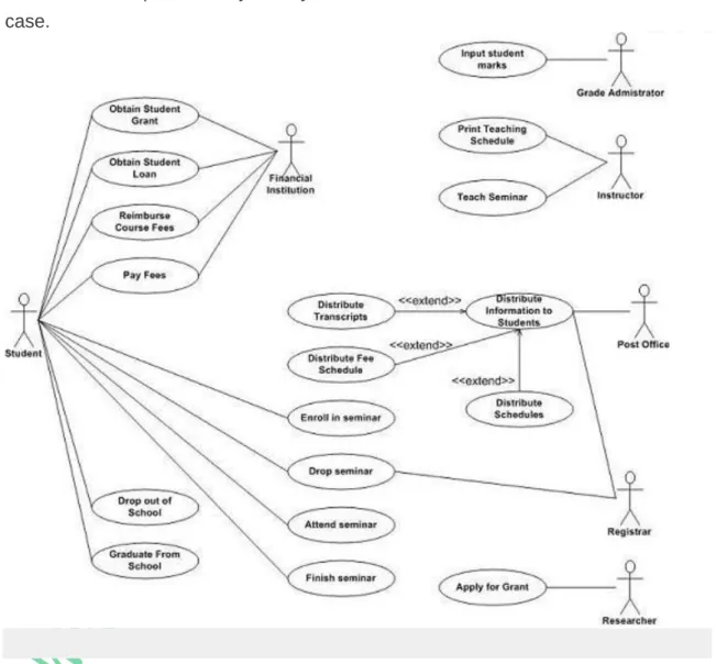
In the example depicted in Figure 1 students are enrolling in courses with the potential
help of registrars. Professors input the marks students earn on assignments and
registrars authorize the distribution of transcripts (report cards) to students. Note how for
some use cases there is more than one actor involved. The association between
Student and Enroll in Seminar indicates this use case is initially invoked by a student
and not by a registrar. Understanding that associations don’t represent flows of
information is important; they merely indicate an actor is somehow involved with a use
case.
Figure 1. System use case diagram.
Depicts a UML sequence diagram for the Enroll in University use case, taking a
system-level approach where the interactions between the actors and the system are show. I will
often develop a system-level sequence diagram with my stakeholders to help to both
visualize and validate the logic of a usage scenario. It also helps me to identify
significant methods/services, such as checking to see if the applicant already exists as a
student, which my system must support.
Figure: 1 System-level sequence diagram.
Question 3:
Draw a DFD for Library Management System.
Solution:
Question: 4
What is an instance diagram? Draw an instance diagram for the arithmetic expression:
A= (B+C*D)/(B-C+D).
Solution:
Object diagrams are derived from class diagrams so object diagrams are dependent
upon class diagrams.
Object diagrams represent an instance of a class diagram. The basic concepts are
similar for class diagrams and object diagrams. Object diagrams also represent the
static view of a system but this static view is a snapshot of the system at a particular
moment.
Object diagrams are used to render a set of objects and their relationships as an
instance.
Question: 5
What are different types of Object Oriented models? Explain the types of
characteristics represented by these models.
Solution:
Object model: Object models are used for describing the objects in the system and their
relationship among each other in the system.
Dynamic model: The dynamic model describes interaction among objects and information
flow in the system.
Functional model: The data transformations in the system are described by a functional
model.
Note:
All three models are applicable during all stages of development
.
The three types of characteristics represented by these models:
Class and Objects
A
class
is a collection of things, or concepts that have the same characteristics. Each of
these things, or concepts is called an
object.
Classes define the basic words of
the
system being modeled
. Using a set of classes as the core vocabulary of a software
project tends to greatly facilitate understanding and agreement about the meanings of
terms, and other characteristics of the objects in the system.
Objects
The notation for an object is the same in basic form as that for a class. There are three
differences between the notations, which are:
Within the top section of the class box, the name of the class to which the object belongs
appears after a
colon
. The object may have a name, which appears before the colon, or it
may be anonymous, in which case nothing appears before the colon.
The contents of the top compartment are underlined for an object.
Each attribute defined for the given class has a specific value for each object that belongs
to that class.
Links and Association
Links and associations are the basic means used for establishing relationships among
objects and classes of the system.
General Concepts
A link is a physical or conceptual connection between objects for example, a
student,
Ravi study in IGNOU
. Mathematically, you can define a link as a tuple that is
an ordered list of objects. Further, a link is also defined as an instance of an association.
Multiplicity
Multiplicity in an association specifies how many objects participate in a relationship.
Multiplicity decides the number of related objects. Multiplicity is generally explained as
“one” or “many,” but in general it is a subset of the non-negative integers.
Aggregation
relationship as an aggregate (the whole) and parts. The most considerable property of
aggregation is transitivity, that is, if X is part of Y and Y is part of Z, then X is part of Z.
Aggregation is seen as a relationship in which an assembly class is related to
component class.
Generalization and Inheritance
Generalization
Generalization and inheritance are powerful abstractions for sharing the structure and/or
behaviour of one or more classes. Generalization is the relationship between a class,
and it defines a hierarchy of abstraction in which subclasses (one or more) inherit from
one or more superclasses. Generalization and inheritance are transitive across a
subjective number of levels in the hierarchy. Generalization is an “is-a-kind of”
relationship, for example, Saving Account is a kind of Account, PG student is kind of
Student, etc. The notation for generalization is a triangle connecting a super class to its
subclasses.
Inheritance
Inheritance is taken in the sense of code reuse within the object oriented development.
During modeling, we look at the resulting classes, and try to group similar classes
together so that code reuse can be enforced. Generalization, specialization, and
inheritance have very close association. Generalization is used to refer to the
relationship among classes, and inheritance is used for sharing attributes and operations
using the generalization relationship. During inheritance, a subclass may override a
superclass feature by defining that feature with the same name. The overriding features
the subclass feature with the same names of superclass features) refines and replaces
the overridden feature (the superclass feature).
Question: 6
What is state diagram? Explain its advantages. Draw state diagram for Railway Ticket
Booking on IRCTC website.
Solution:
A state diagram, also called a state machine diagram or statechart diagram, is an
illustration of the states an object can attain as well as the transitions between those
states in the Unified Modeling Language (UML). In this context, a state defines a stage
in the evolution or behavior of an object, which is a specific entity in a program or the
unit of code representing that entity. State diagrams are useful in all forms of
object-oriented programming (OOP). The concept is more than a decade old but has been
refined as OOP modeling paradigms have evolved.
The obvious advantage of extended state machines is flexibility. For example, extending
the lifespan of the “cheap keyboard” from 1,000 to 10,000 keystrokes would not
changing the initialization value of the key_count down-counter in the initial transition.
This flexibility of extended state machines comes with a price, however, because of the
complex coupling between the “qualitative” and the “quantitative” aspects of the
extended state. The coupling occurs through the guard conditions attached to
transitions.
Question: 7
What is need of concurrency management in Object Oriented Systems? Explain the
important issues related to concurrency management with the help of an example.
Solution:
Design model objects are not concurrent in nature
as a
single process may
support multiple objects. Concurrency in objects can be identified by the way they
change state
. Current objects can change state
independently
. Aggregation implies
concurrency. Concurrency in OOAD study is described and studied in
dynamic
objects. Once we identify non-concurrent (mutually exclusive) objects, we can fold all the
objects together in
one thread of control, or process
. On the other hand, if the objects
are concurrent in nature we have to assign them to,
different thread of control
. For
example, withdraw and deposit operations related to a bank account may be executed in
parallel (concurrently).
A thread of control is a path through a set of state diagrams on which a single object is
active at a time.
Objects are shared among threads, that is, several methods of the same object can be active
at the same time.
Thread splitting: Object sends a message but does not wait for the completion of the
method.
Concurrency issues
Data integrity:
Threads accessing the same object need to be synchronized, for example:
banking account.
Deadlock: One or more threads in the system are permanently blocked. Example: Thread A
waiting on Thread B, which is waiting on Thread A.
Starvation: A thread is not getting enough resources to accomplish its work. Example: All
requests from one user are being handled before another users requests.
Question: 8
What is association in UML Diagram? Briefly explain different types of associations
available in UML. Also explain the process of mapping a ternary association into
database table.
Solution:
Association is a relationship between classifiers which is used to show that instances of
classifiers could be either linked to each other or combined logically or physically into
some aggregation. UML specification categorizes association as semantic relationship.
Some other UML sources also categorize association as a structural relationship.
Association
could be used on different types of UML
structure diagrams:
class diagram associations
: Class diagram is UML structure diagram which shows
structure of the designed system at the level of classes and interfaces, shows
their features, constraints and relationships
- associations, generalizations, dependencies, etc.
Some common types of class diagrams are:
diagram of implementation classes.
Use case diagram associations:
Each use case represents a unit of useful functionality
that subjects provide to actors. An association between an actor and a use case indicates
that the actor and the use case somehow interact or communicate with each other.
Only binary associations are allowed between actors and use cases. An actor could be
associated to one or several use cases.
Deployment diagram artifact associations:
An artifact is a classifier that represents
some physical entity, a piece of information that is used or is produced by a software
development process, or by deployment and operation of a system. Artifact is a source of
a deployment to a node. A particular instance (or “copy”) of an artifact is deployed to a
node instance.