Real-time Data Streaming Architecture and
Intelligent Workflow Management for
Processing Massive Ecological Videos
Gayathri Nadarajan, Cheng-Lin Yang
Yun-Heh Chen-Burger
School of Informatics, University of Edinburgh 10 Crichton St, Edinburgh EH8 9AB U.K.
[email protected], [email protected], [email protected]
Yu-Jung Cheng, Sun-In Lin
Fang-Pang Lin
National Center for High-Performance Computing, NARL Hsinchu Science Park, Hsinchu City, Taiwan, R.O.C. 30076 [email protected],{lsi,fplin}@nchc.narl.org.tw
Abstract—We present data collection and storage utilities and a workflow management system for handling the processing of large volumes of videos collected from an ecological source over several years and still growing. They lie in the heart of an integrated system that brings together expertise from various disciplines, including marine science, image processing, high performance computing and user interface. A real-time data streaming architecture was developed for efficient collection and storage of videos. In the analysis part, a workflow management system with two main components was deployed; i) a workflow en-gine and ii) a workflow monitor. The workflow enen-gine deals with on-demand user queries and batch queries, selection of suitable computing platform and invocation of optimal software modules, while the workflow monitor handles the seamless execution and intelligent error handling of workflow jobs on a heterogeneous computing platform. We discuss the challenges that lie ahead for the workflow system such as the demand for more sophisticated scheduling and monitoring.
I. INTRODUCTION
The pervasiveness of video data has proliferated the need for more automated and scientific methods to store and anal-yse them. In particular, continuous collection of video data e.g. surveillance videos and satellite images, are of major concern because they cause the accumulation of ‘big data’. In Fish4Knowledge (F4K) [1][2], hundreds of underwater video clips are collected daily by NCHC, National Applied Research Laboratories (NARL), Taiwan and made available to marine biologists for long-term monitoring, so that they can make observations such as marine life population changes and behaviours. 10 underwater cameras were installed in four locations capturing streams of 10-minute video clips for 12 hours each day. The locations include Kenting Nuclear Power Plant (NPP-3), Hobihu Harbour, Lanyu Island and National Museum of Marine Biology and Aquarium (NMMBA).
However, pure manual-based observation and analysis of these videos is unfeasible; one minute’s video clip requires approximately 15 minutes’ human effort on average for basic processing tasks which include viewing the clip, labelling interesting frames, adding brief annotation and basic classi-fication of the clips. Currently, continuous video recording
This research was funded by the European Commission (FP7 grant 257024) and the Taiwan National Science Council (grant NSC100-2933-I-492-001) and undertaken in the Fish4Knowledge project (www.fish4knowledge.eu).
has been collected over the past 5 years, and it is rapidly increasing, reaching 100 Terabytes in the near future. We attempt to efficiently store, analyse and communicate these videos and corresponding analysed results to marine biologists using computational-assisted solutions in the form of user in-terfaces, image processing tools, databases, high performance computing and workflow technologies. In particular, we are deploying a flexible workflow framework that will enable us to talk with a sophisticated front end user system that manages complex user queries. Based on queries and requirements, this workflow system will retrieve appropriate video processing software modules, run them in high performance computing facilities and monitor their execution.
We first provide an overview of F4K’s hardware archi-tecture in Section II, followed by the data collection and storage utilities (Section III). The overview of the workflow system is given in Section IV, with its main components described in Section IV-A (Workflow Engine) and Section IV-B (Workflow Monitor). Section V discusses our current progress and concludes.
II. OVERVIEW OFF4K’SHARDWAREARCHITECTURE
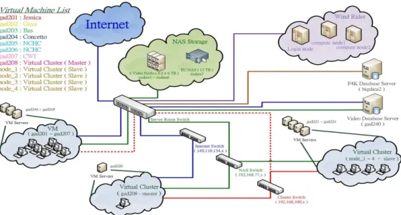
F4K’s parallel capabilities (Figure 1) consist of high per-formance computing machines that can be virtual machine (VM) servers, storage devices for videos, computing nodes and database servers. In the architecture, the VM group is provided for accessing NARL’s computational resources and can also act as computing nodes for process execution. There are several servers to run VMs to support various operation demands and tasks. They are then mapped to VM machines that act as computational nodes for process execution. There are three networks that inter-connect the computational resources, stor-age resources and internet for remote ssh/vnc accessing. The video storage and F4K database servers are connected in the network too. Storage is connected in a private network which is not directly accessible from public domains. Because of the security policy of NARL, the Windrider supercomputer can not be accessed from foreign IP address. Internal virtual machines can be used to access Windrider. Currently, all resources are connected with 1GB network. In the future, the network will be upgraded to a 10GB infrastructure to provide high-speed data transmission between resources.
Fig. 1. An overview of the hardware architecture available for F4K. The main components include high-performance computing machines, database servers, video storage facilities and web servers.
Next, the methods used for capturing data and storing them efficiently for archival and analysis purposes are outlined.
III. DATACOLLECTION ANDSTORAGE OFUNDERWATER
VIDEOS USINGREAL-TIMESTREAMING
In order to store and provide long-term underwater video data from ecological sites, we implemented a real-time stream-ing architecture to capture data, to transmit them over the internet and to store them into a central storage in NARL. Fig. 2 shows the architecture of underwater video capturing and streaming in the Kenting Nuclear Power Plant (NPP-3) site. There are four underwater CCTV cameras installed in a 5-meter deep seabed. The entire streaming architecture includes several stages that continuously receive and transmit stream data to the central storage. Due to lack of internet accessibility and security policy in NPP-3, all video streams have to be sent to Taipower Museum; which has public network infrastructure and that allows accessing the internet via ADSL line. The distance between the dike and the Taipower control room is about 400 meters and 5000 meters between the Taipower control room and the Taipower Museum. Fiber connection is used to connect streaming devices in those places. All streaming devices are in the same private network and able to directly access one another via SSH for maintenance purposes. The architecture is designed to fit the requirement for i) storing high quality videos; ii) improving the overall system stability; and iii) reducing the overhead cost of system main-tenance. The video server that receives video signals from undersea cameras is located in an indoor position, the Taipower control room. The Taipower control room provides constant temperature and humidity for long term and steady operation for the video server. This reduces errors and failure in the first stage of raw video source data production prior to video streaming and storing. In Taipower Museum, the media server converts raw video data to lower bit-rate streaming to fit actual data uploading capability of each ADSL connection. The resolution is converted to 640x480 and frame rate to 24
Fig. 2. The real-time streaming flow architecture in NPP-3 site. It provides long-term underwater video data stream and high bit-rate videos which are locally stored.
fps (from 8 fps). Because the CCTV uses interlaced scanning, de-interlace(linear) is used in the streaming conversion. Table I shows all video formats that used in different ecological sites.
TABLE I. SUMMARY OF VIDEO COLLECTION FORMAT IN ECOLOGICAL SITES.
CCTV CCTV HD Format FLV MPEG4 FLV Resolution 640x480 640x480 1280x760 De-Interlace mode linear linear none
FPS 24 24 30
Bit-rate 1M 5M 20M Capturing method Stream dump Stream dump Stream dump Site NPP-3, Lan Yu, Hobihu NPP-3 NMMBA
To capture and store video data into file system from real-time video streaming, we use thestream dump method. This method directly saves video data from its streaming source to available storage. It dumps a new data streaming from source streaming and streaming to network or record into file system. This makes video capturing more accurate and controlled. The
video data received from NPP-3 site are converted into FLV format and stored in the central storage in NARL.
Due to network bandwidth constraints between NPP-3 site and NARL, it is not feasible to transmit and store real-time high bitrates video in NARL’s central storage. Therefore, we implemented a solution by installing a new server (Local Processing Server) and 11 TB local storage (NAS Server) in NPP-3 site. The local processing server is used to convert native/raw video stream data to H.2641 and MPEG4 format in high bitrates (5M). However, converting videos to H.264 format needs six times more processing time than converting to MPEG4. It would not be possible to convert and store each source video within 10 minutes. The MPEG4 format is chosen because the converting time is less than 10 minutes and requires less compute resources. The local storage is capable of storing about 4 months of MPEG4 format video (calculated by average video size 300 MB, 10 minutes video length, 12 hours recording per day). It also compares better with other video formats. The high bitrate videos provide a clear and reliable data source for further video analysis. When the local storage is full of video data, NARL will replace the hard disks in the local storage (NAS) with new ones. The old hard disk (with video data) will be taken back to NARL and archived in the central data storage.
The storage is also enhanced, Redundant Array of In-dependent Disks (RAID) is used in RAID 6 mode in the storage of NPP-3 site to provide higher data protection level. Additionally, Remote Power Management (RPM) is installed to provide feasible system and service recovery when the server crashes. For video storage in NARL, the size of the storage is increased by upgrading it with 3TB sized hard disks. Two video NAS (NAS 1 and 2) are upgraded from size of 8.2 TB to 14 TB (Figure 3). 10 GB network infrastructure is ready for implementation. A 10G Ethernet switch is installed to connect computational and storage resources. 10GB network environment will be ready after all servers and storage re-sources are installed with 10GB Network Interface Card (NIC) and connected to the 10G Ethernet switch with 10GB Ethernet cable.
Fig. 3. Topology of the upgraded data storage.
As of April 8th, 2013, there were a total of 613,004 videos recorded in video database and 41,977 high bitrates video collected in storage (Table II). As more and more video data 1New video codec standard which can achieve high quality video in
relatively low bitrates.
is captured and updated to the video database, fast query-ing and retrieval of video information and data is designed for video download stage in workflow. Universally unique identifier (UUID) is implemented in the video database for indexing videos to improve data query efficiency. This is more powerful than using integers as indexes. A five tier hierarchical database acceleration architecture is used for caching video information and reducing database search loading. Because distributed storage is used in video NAS, the directory for storage mounting is redesigned, which allows data accessing across many storages devices in the storage pool.
TABLE II. NEW FORMAT AND METHOD FOR CAPTURING AND STORING VIDEOS.
Video Format Video Bitrate Site Name No. video No. video record in storage in database FLV 200K/480K / All Sites 635,672 613,004
1M/2M (40207 new) (39267 new) MPEG4 5M NPP-3 41,977 none
The data storage facility is built for storing huge amounts of video data and processed data after video processing. NARL built high-performance Network Attached Storage (NAS) to store video data in the first stage. It allows data sharing in many different types of machines and operation systems and will provide 10G data transmission capability in 10G network after upgraded with 10G NIC. It also takes advantages of less administration overhead but still provides a console interface for fine-tuning and provides many additional ready-to-use services for data sharing such as Network File System (NFS), Samba and HTTP.
In order to enable the use of storage facilities by com-putational resource servers, NFS is used to provide feasible and reliable storage mounting. NFS is easy to setup on any Linux system and provides efficient large data transmission. Samba will be considered as an alternative and its suitability for storage sharing and accessing will be further evaluated.
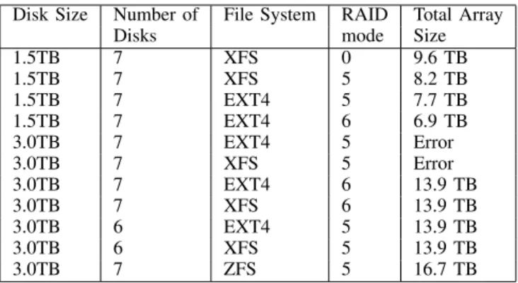
TABLE III. CAPABILITY OF STORAGE IN DIFFERENTFILESYSTEMS ANDRAIDMODE.
Disk Size Number of File System RAID Total Array
Disks mode Size
1.5TB 7 XFS 0 9.6 TB 1.5TB 7 XFS 5 8.2 TB 1.5TB 7 EXT4 5 7.7 TB 1.5TB 7 EXT4 6 6.9 TB 3.0TB 7 EXT4 5 Error 3.0TB 7 XFS 5 Error 3.0TB 7 EXT4 6 13.9 TB 3.0TB 7 XFS 6 13.9 TB 3.0TB 6 EXT4 5 13.9 TB 3.0TB 6 XFS 5 13.9 TB 3.0TB 7 ZFS 5 16.7 TB
RAID storage technology is used to take advantage of data security in the NAS with RAID 5 and RAID 6. Different RAID modes provide different levels of security, performance overhead and storage capability, as shown in Table III. RAID 5 is adopted for video NAS to maximise storage capability for storing source video. It also prevents the storage array from being destroyed by a single disk failure. NARL built a high-end NAS storage which installed 58 hard disks to establish a single huge volume of storage. The newly built storage (NAS 9) comes with 125 TB storage capability in RAID 6 mode
which provides hardware acceleration to read and write data in RAID. Total up to 198.8TB of data storage size in NARL is built for data storage.
To reduce the potential risk of network attacks such as Denial of Service (DoS) and to maintain network performance, security of data storage the storage is protected by locating it in a private network to avoid direct network attacks from public network. Database accessing is allowed from internal VM group and Windrider. In the future, we will use curlfs, which uses the libCurl library [3] for HTTPS access to files on remote webservers (but is read-only) orWebDAV[4] to mount storage in Storage Area Network (SAN) as random-access file system.
We now turn to the application and analysis of the data by the workflow management system.
IV. WORKFLOWMANAGEMENTOVERVIEW
Fig. 4. The F4Ks workflow component binds high level workflow queries from the user interface to low level image processing components via process planning and composition. It also schedules and monitors the execution of the video processing tasks on a high performance computing environment and reports feedback to the user interface component
The workflow component lies in the heart of the F4K system and plays a vital part in integrating all the other system components. The requirements for such a component are:
• Process automation for non experts: manual process-ing of large data sets by marine biologists would be unfeasible.
• Rich process modelling traits: iterative processing, conditional branching, etc., would be required to deal with typical processing of video analysis tasks.
• Performance-based software selection: an automatic mechanism is required to select one of many algo-rithms that exist to perform the same family of tasks.
• Speedvs.accuracy: an ideal system would be one that is generic in architecture that balances speed of the processing with accuracy of the results.
A workflow management system was designed and im-plemented based on these requirements and is shown dia-grammatically in Fig. 4. Two types of queries are dealt by the workflow - on-demand queries from the user interface and internal batch queries. On-demand queries are those that
originate from the user that have high priorities and should be processed immediately. These on-demand queries can be one of the following:
Q1 Detect and track all the fish in a given date range and set of camera locations.
Q2 Identify all the fish species in a given date range and set of camera locations.
Q3 Estimate how long a detection or recognition query will take to produce results, without sending the query for execution.
Q4 Abort a query that is currently being processed. Internal batch queries are those that are invoked by the workflow management system itself. This is predominantly batch tasks on newly captured video clips that involve fish detection and tracking (Q1 above) and fish species recognition (Q2 above). These batch queries are considered to have low priority and are scheduled to be executed at “quiet” times, i.e. when on-demand queries are least likely to be processed.
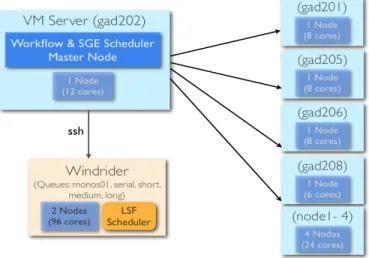
Fig. 5. The F4K computing environment is a heterogeneous platform made up of a group of virtual machines (VM cluster) and a supercomputer (Windrider).
At present the compute environment consists of nine nodes on a cluster of virtual machines with a total of 66 CPUs (called VM cluster) and two nodes on a supercomputer with a total of 96 CPUs (called Windrider). The workflow system resides in the master node of the VM cluster and makes use of both platforms to process queries. It deals with two different resource schedulers; Gridengine (SGE) [5] on the VM cluster and Load Sharing Facility (LSF) [6] on Windrider (Fig. 5).
The next section will outline the workflow engine which listens for queries, composes them as video processing jobs and sends these jobs for execution onto the compute platforms, while section IV-B will outline the workflow monitoring sys-tem which oversees the execution of the jobs and deals with errors.
A. Workflow Engine
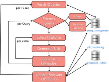
The workflow engine is a standalone component which constantly listens for new queries and processes them. Its overall design is given in Fig. 6. It integrates with other compo-nents in the F4K system via database tables; it communicates
Fig. 6. The workflow engine is responsible for processing on-demand user queries & batch tasks. It composes & schedules video processing jobs and updates relevant database tables to pass control to the workflow monitor.
with the user interface via thequery managementtable, video processing modules via the processed videos table and with the workflow monitor via thejob monitoring table.
When the workflow detects a query, it first recognises the type of query, which can be compute-intensive (Q1 and Q2) or not compute-intensive (Q3 and Q4). Runtime estimation is calculated based on average execution times that have been aggregated and recorded over time. Table IV below shows the statistics for the average execution times for the best performing modules in the F4K system.
TABLE IV. STATISTICS OF AVERAGE EXECUTION TIMES AND WAITING TIMES FOR FISH DETECTION(COMPONENT ID80)AND FISH RECOGNITION
(COMPONENT ID52)ONWINDRIDER IN MONTHMARCH2013
Component Average time Average waiting No. videos Max. time Min. time id (s) time (s) processed (s) (s) 52 11,248 561 4,457 469,603 0
(>3 hrs) (>9 mins) (>130 hrs) 80 8,000 32,176 2,180 77,271 2
(>2 hrs) (<9 hrs) (>21 hrs)
An abort query requires all the executing jobs related to the query to be terminated. This will be described in the workflow monitoring section. For compute-intensive queries (Q1 and Q2), the workflow will need to select a platform for execution. Two types of such queries can exist; high priority (user) queries and low priority (batch) queries. At present all high priority jobs are scheduled on the Windrider platform, while the low priority jobs are split equally between the VM cluster and Windrider.
Batch queries are initiated internally by the workflow. At present, the workflow looks for new unprocessedvideos over the last 24 hours from the database. If no new unprocessed videos are present, it looks for hourly unprocessed historical videos and creates fish detection and tracking queries in the database which will be caught by the workflow engine. Failing that, it looks for half hourly unprocessed videos and creates fish detection and tracking queries.
After selecting the appropriate platform for a query, the
workflow engine retrieves each video associated with that query. An example query is “What is the overall fish population in the Nuclear Power Plant (NPP-3) station between January and March 2012?”. The user interface component deals with presenting the query and results to the user. For each video, the command line call including the invocation of the resource scheduler and the selection of appropriate algorithms for that query type will be generated by the workflow engine. This is done via a planning-based workflow composition mechanism [7]. Using this mechanism, new software modules with en-hanced algorithms can be easily added, detected and selected by the workflow engine. The planning plays an important part in performance-based selection of video processing software modules. The command line call that is sent to the scheduler to process each video is known as a job.
Another important feature of the workflow engine is in dealing with job dependencies. This scenario applies to fish species recognition jobs (Q2). A fish recognition module can only be applied to a video when a fish detection module has
already processed it. The workflow engine deals with a fish species recognition job as follows:
• If fish detection has been completed on the video, then run fish recognition only.
• If fish detection has not been started, run fish detection and fish recognition, specifying a dependency flag between them.
• If fish detection has been started but not completed yet, run fish recognition with a dependency flag on the running fish detection job.
The workflow schedules a maximum of 300 batch jobs (i.e. process 300 videos) every 24 hours and listens for new on-demand queries every 10 seconds. Implementation-wise, there are two daemon processes for i) managing the queries (every 10 seconds); and ii) creating batch jobs (every 24 hours).
When the jobs are executing, the workflow monitors them for successful completion, or deals with errors that occur. The workflow can handle various scenarios on the Windrider facility while development is on-going to have similar handling strategies on the VM cluster. This is because they both use different resource schedulers and different mechanisms are needed to deal with these two schedulers.
B. Workflow Monitoring
Although LSF and SGE provide basic job status monitoring functions, they are not intelligent enough to handle different types of job executing scenarios that need more sophisticated methods to be dealt with. For example, a low priority job could end up starving if it has been waiting in the queue which is constantly packed with high priority ones. Therefore, it is essential to build a smart job status monitoring and error handling system to tackle different job executing scenarios.
Another benefit of having a job status monitoring and error handling system is to provide real-time and detailed statistics of the progress of each query. It allows the user to be able to track up-to-date status of his/her request. Currently, the system is able to compute the following statistics:
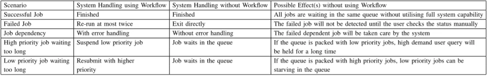
TABLE V. SUMMARY OF POSSIBLE IMPACTS WHEN ERROR HANDLING SYSTEM IS NOT USED
Scenario System Handling using Workflow System Handling without Workflow Possible Effect(s) without using Workflow
Successful Job Finished Finished All jobs are waiting in the same queue without utilising full system capability Failed Job Re-run at most twice Exit directly The failed job will not be detected until the user checks the status manually Job dependency With error handling Without error handling The failed dependent job will be taken care by the system
High priority job waiting Suspend low priority job Job waits in the queue If the queue is packed with low priority jobs, high demand user query will too long be held for a long time
Low priority job waiting Resubmit with higher Job waits in the queue If the queue is packed with high priority jobs, low priority jobs can be too long priority starving in the queue
2) The percentage of successful job executions of each user query.
3) The percentage of abandoned job executions (by user and system) of each user query.
4) The percentage of pending jobs of each user query.
Fig. 7. The workflow monitoring system is responsible for handling different execution scenarios. It updates each job status and statistics to relevant database tables.
The job status monitoring and handling system is designed to run in parallel with the workflow engine to support the workflow system, by regularly checking status of scheduled jobs in the queue. Fig. 7 shows the high-level design architec-ture of the system. It communicates with the workflow engine via the job monitoring table; it updates job statistics via the
query managementandjob monitoringtable.
There are two major components in workflow monitoring system: 1) Job status classifier and 2) Event Handler. Job status classifier constantly inspects a job’s status and classifies it into one of five categories: Pending, Running, Suspending, Failed (abnormal) and Done (success). Each job category has its own event handler that was carefully designed to handle the possible execution scenarios described below:
1) Pending jobs: The workflow engine may schedule hun-dreds or thousands of high priority jobs per on-demand query. It also processes up to 300 low priority background jobs on a daily basis. Therefore, it is possible that an individual job will be waiting in the queue for a long time. The event handling procedure has different pending time thresholds based on the job priority. High priority jobs have much shorter thresholds than low priority jobs. If a high priority job, which needs to be processed immediately, has been pending longer than its waiting threshold, the event handler will check if there is any low priority job in the queue and suspends it to make sure that the high priority job can be executed shortly.
If the event handler detects a low priority job that has been pending longer than its waiting threshold, it will kill the job and resubmit it with the highest priority to make sure it will be executed and not starved in the queue. The main reason that the event handler uses the kill-and-resubmitaction is that the supercomputer platform disallows the user to alter the job priority of submitted jobs. The only solution to increase the priority is to kill the pending job and resubmit it with a higher priority.
2) Prolonged jobs: If a job is running longer than expected, it might have encountered unexpected problems and waste valuable computing resource. The average execution time for a job varies with the software module (component id) that is selected for execution (see Table IV). During the development phase, there is not much statistics to help us to determine the optimal threshold. Hence, at present, the maximum running time limit has been set as 3 times the average execution time of the assigned component id of the job. When the system is in the full production run, an optimal threshold will be determined based on empirical statistics.
If the job running time is longer than its threshold, it will be considered as a failed job (Item 4 below). The event handler will be triggered to kill and resubmit the job to the scheduler. When the event handler resubmits the job, it also keeps track of the number of times the job has been submitted to the scheduler. If a job has been submitted to the scheduler twice, it will be killed and marked as a failed job. This prevents further wasting of computing resource.
3) Suspended Jobs: A job may be suspended by the workflow engine or the scheduler itself. A mechanism exists to ensure that a job is not suspended for longer than a predefined threshold. The event handler will be triggered when this threshold is exceeded, where it will resume the suspended job.
4) Failed Jobs: An executing job might fail due to various reasons such as computing node failed, missing data or internal interconnection issue. This will be relayed as an exit status by the scheduler. To increase the successful completion chances of such failed jobs, the event handler adopts resubmit policy. If a running job exits unexpectedly or finishes with and error code, the event handler will be triggered and resubmit the job back to the queue. In order to have a balance between job resubmission times and effective computing resource usage, the failed job will only be resubmitted twice.
5) Completed Jobs: If a job is completed successfully, the event handling will update the final job execution statistics to
job monitoringandquery managementtable.
6) Dependent Jobs: Although job dependencies are dealt by the workflow engine as mentioned in Section IV-A, the
workflow monitoring system still applies the same policies (1-5) above to each depending job. When the jobs that have other jobs depending on them fail or face unforeseen circumstances, the workflow monitor will handle them as any other job, while any effects that will have on the dependent jobs will be handled internally by the scheduler.
In order to understand the performance of the error han-dling system with respect to the hanhan-dling of different job status, we have decided to study its impact on the overall system when the workflow system is not used. Table V above summarises how each scenario is handled in the presence and absence of the workflow. Additionally it states the possible effects on the system when the job monitoring and error handling system is not used.
In summary, we can conclude that when the system does not make use of the workflow, suitable resources and queues are not being selected. Jobs that fail are not rerun and in extreme cases some jobs can starve. All these factors affect the overall system performance.
V. CURRENTPROGRESS ANDCONCLUSIONS
We have presented an architecture for real-time data streaming and an intelligent workflow management solution to handle the problem of big data in the ecological domain. Sophisticated video capture and storage methods leads to better data provision and processing by other F4K components. This was done via an improved observation system for capturing undersea videos, and enhanced video quality for video pro-cessing by adopting new video format and using stream dump as a capturing method. A total of 198.8 TB data storage facility was also provided.
By having the workflow management system, we can automatically 1) trigger the execution of on-demand user queries and historical data processing (batch queries); 2) make use of several computing resources for distributing jobs; and 3) monitor jobs and handle special circumstances such as failed jobs, dependent jobs and jobs executing or waiting for too long. Efforts are underway to prepare the workflow management system for production run. We aim to improve the system’s overall performance by reducing the average execution and waiting times. We will also investigate the best threshold values for maximum running time limit, suspension limit and resubmission limit. We will continue to understand the different behaviours of the two resource schedulers and make use of them optimally.
REFERENCES
[1] F4K, The Fish4Knowledge Project, 2010-2013, http://www.fish4 knowledge.eu.
[2] B. J. Boom, P. X. Huang, C. Spampinato, S. Palazzo, J. He, C. Beyan, E. Beauxis-Aussalet, J. van Ossenbruggen, G. Nadarajan, Y. H. Chen-Burger, D. Giordano, L. Hardman, F.-P. Lin, and R. B. Fisher, “Long-term underwater camera surveillance for monitoring and analysis of fish populations,” inVAIB12, 2012.
[3] LibCurl, The Multiprotocol File Transfer Library, http://curl. haxx.se/libcurl/.
[4] WebDAV, Web-based Distributed Authoring and Versioning, 2010,
http://www.webdav.org/.
[5] Oracle, Open Grid Scheduler (SGE), http://gridscheduler. sourceforge.net/.
[6] IBM,Load Sharing Facility (LSF),http://www-03.ibm.com/sys tems/technicalcomputing/platformcomputing/products/lsf. [7] G. Nadarajan, Y. H. Chen-Burger, and R. B. Fisher, “Semantics and
Planning Based Workflow Composition for Video Processing,”Journal of Grid Computing, Special Issue on Scientific Workflows, 2013, (in press).
[8] J. Wu, T. Chung, F. Lin, and W. Tsai, “A Scalable Middleware for Multimedia Streaming,” inHPC Asia, 2009.
[9] H. Chou, Y. Shiau, S. Lo, S. Lin, F. Lin, C. Kuo, and C. Lai, “A Real-time Ecological Observation Video Streaming System Based on Grid Architecture,” inHPC Asia, 2009.
[10] NARL, Windrider Supercomputer. National Center for High Performance Computing (NCHC), Taiwan, 2011, http://www. nchc.org.tw/tw/services/supercomputing/supercomputing_1/ ar585f1.php.
[11] N. Lin, T. Fan, F. Lin, K. Shao, and T. Sheen, “Monitoring of of Coral Reefs at the Intake Inlet and Outlet Bay of the 3rd Nuclear Power Plant in Southern Taiwan,” inAnnual Meeting of The Fisheries Society of Taiwan, 2009, pp. 19–20.