Grid-connected Inverter
Downloaded from: https://research.chalmers.se, 2020-04-24 15:19 UTC
Citation for the original published paper (version of record):
Yang, T., Cai, Z., Xun, Q. (2019)
Adaptive Backstepping-based H8 Robust controller for Photovoltaic Grid-connected Inverter
IEEE Access, In Press
http://dx.doi.org/10.1109/ACCESS.2019.2962280
N.B. When citing this work, cite the original published paper.
©2019 IEEE. Personal use of this material is permitted.
However, permission to reprint/republish this material for advertising or promotional purposes
or for creating new collective works for resale or redistribution to servers or lists, or to
reuse any copyrighted component of this work in other works must be obtained from
the IEEE.
This document was downloaded from http://research.chalmers.se, where it is available in accordance with the IEEE PSPB Operations Manual, amended 19 Nov. 2010, Sec, 8.1.9. (http://www.ieee.org/documents/opsmanual.pdf).
SPECIAL SECTION ON ARTIFICIAL INTELLIGENCE TECHNOLOGIES FOR ELECTRIC POWER SYSTEMS
Received November 19, 2019, accepted December 13, 2019, date of publication December 25, 2019, date of current version January 28, 2020.
Digital Object Identifier 10.1109/ACCESS.2019.2962280
Adaptive Backstepping-Based H
∞
Robust
Controller for Photovoltaic
Grid-Connected Inverter
TONGGUANG YANG 1, ZHENHUA CAI 1, AND QIAN XUN 2
1College of Mechanic and Electrical Engineering, Hunan City University, Yiyang 413000, China 2Department of Electrical Engineering, Chalmers University of Technology, 41279 Göteborg, Sweden
Corresponding authors: Tongguang Yang ([email protected]) and Qian Xun ([email protected])
This work was supported in part by the National Nature Science Foundation for China under Grant 61321003 and Grant 61290325, in part by the Zhejiang Natural Science Foundation under Grant LY19F030002, and in part by the Huzhou Public Welfare Application Research Project under Grant 2019GZ02.
ABSTRACT To improve the robustness and stability of the photovoltaic grid-connected inverter system, a nonlinear backstepping-based H∞controller is proposed. A generic dynamical model of grid-connected
inverters is built with the consideration of uncertain parameters and external disturbances that cannot be accurately measured. According to this, the backstepping H∞ controller is designed by combining
techniques of adaptive backstepping control and L2-gain robust control. The Lyapunov function is used
to design the backstepping controller, and the dissipative inequality is recursively designed. The storage functions of the DC capacitor voltage and grid current are constructed, respectively, and the nonlinear H∞
controller and the parameter update law are obtained. Experimental results show that the proposed controller has the advantage of strong robustness to parameter variations and external disturbances. The proposed controller can also accurately track the references to meet the requirements of high-performance control of grid-connected inverters.
INDEX TERMS Robustness, grid-connected inverter, H∞controller, adaptive backstepping control, L2-gain
robust control.
I. INTRODUCTION
The renewable energy sources, such as wind turbines, solar cells, and fuel cells, have been significantly increased atten-tion over decades due to the technical and environmental benefits [1]. There are several different ways to reuse these renewable energy sources, and among them, solar photo-voltaic (PV) system has been receiving a great deal of interest from the researchers due to the intrinsic advantages, such as no fuel cost, no pollution and widely distributed throughout the world. Grid-connected voltage source inverters (VSIs), as an interface to connect the PV system and the utility grid, play an essential role to transfer power to the grid [2]. During the power transmission process, the power quality would be affected by the high-frequency power electron-ics and nonlinear characteristelectron-ics, and the current harmonelectron-ics will be also deduced. Then, the harmonics and unbalanced
The associate editor coordinating the review of this manuscript and approving it for publication was Canbing Li.
negative sequence components will result in the active power fluctuation and the output current distortion. Therefore, the robustness and stability of the grid should also be con-sidered to improve system performance [3].
To improve the dynamic response and the system robust-ness, several control strategies have been proposed based on the mathematical model. Among them, researchers are mainly focused on the classical PI control [3]–[5], PR control [2], predictive control [6]–[8], sliding mode control [9], [35], deadbeat control [10], [11], repetitive con-trol [12] and feedback linearization concon-trol [13]–[15] etc. The approximated linearized model is used in these methods without consideration of the nonlinear features; however, the control performance will be reduced due to parame-ters perturbation and some other disturbances. To avoid the accurate mathematical model of the grid-connected inverter, fuzzy logic control [16] and neural network control [17] are introduced, but their high computational cost would lead to poor real-time performance. Also, some hybrid
methods are proposed in [18], [19]. However, the iden-tification and compensation strategies are needed, mak-ing the control system complicated, and the computational cost is also increased. Furthermore, the uncertainty upper bound of the system is difficult to implement in the filed application.
Robust control, with high stability and robustness, has been successfully applied in a variety of high-performance applications, such as inverter control [20]–[27], rectifier con-trol [28], [29] and motor concon-trol [30]–[32] etc. In [20]–[32], the model inaccuracy, the perturbation, and parameters tolerance are considered. By selecting the proper weight functions, the H∞ controller is designed to solve Riccati
equation [23]-[25], [28], [30]. However, solving the Riccati equation is restricted by the system model, making it com-plicated to implement in real applications. Due to that the perturbation is distributed in the system, the LMI method [22], [26], [31] is usually conservative. The struc-tured singular value (µ) based controller is proposed to improve the system performance, and the robust level and perturbations are expressed by the uncertainties inµ frame-work [21], [27], [29]–[30]. However, conventional solutions to solveµsynthesis problem, such as D–K iteration method, usually lead to a high order system, and the complexity of the system is also increased [36]. Even though the better control performance can be obtained by these methods, but the weight functions are selected through the repeated trial and experience. Due to the nonlinear grid-connected inverter, the approximated linear mathematical model cannot preserve the real quality of the nonlinear system [33].
However, within the academic literature, nonlinear inter-ference suppression strategies for a grid-connected inverter are rare and inconclusive, and the additional identified param-eters are introduced in these control strategies. This paper aims to address this lacuna by proposing a nonlinear adaptive backstepping controller for a grid-connected inverter with the combination of robust control and the backstepping control. The parameters variation and the external disturbances are also considered. To reduce the L2 gain of the closed-loop,
the nonlinear H∞controller is designed using the recursive
dissipative inequality to construct the storage functions for each subsystem. Without designing the weight sensitivity function and solving the feedback transfer function, no addi-tional part is required to identify the model uncertainties. To simplify the system control structure, the nonlinear back-stepping robust controller is used, and the reliability and robustness to parameters perturbation and external distur-bances are also improved.
The remainder of this paper is organized as follows. In section II, a nonlinear model for the grid-connected inverter is built with the consideration of parameters variation and external disturbances. In section III, the nonlinear back-stepping robust H∞controller is derived by applying
back-stepping control and H∞ control. The experimental results
are analyzed in section IV, and finally, the conclusions are drawn in section V.
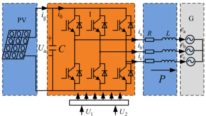
FIGURE 1. The three-phase grid-connected PV system.
II. MATHEMATICAL MODEL OF PHOTOVOLTAIC SYSTEM The basic configuration of a three-phase grid-connected solar PV system is shown in Figure.1. PV represents the pho-tovoltaic array, C is the DC bus capacitor, and I denotes the grid-connected inverter,RandLconstitute the filter cir-cuit, which is used to reduce the ripple components due to the switching actions in PWM schemes, ea, eb, andec are
three-phase grid voltage, respectively. The power switches work in the ideal state, and their rise time, fall time and dead time can be neglected.
In the synchronous rotating dq coordinate system, the mathematical model of the grid-connected inverter can be expressed as [1], [2] did dt = − R Lid+ωiq+ ud−ed L (1) diq dt = − R Liq−ωid+ uq−eq L (2)
where, id, iq denote the d-component and q-component of
the inverter current, ud, uq express the d-component and
q-component of the inverter voltage, respectively.eq,edare
the dq-axis components of the grid voltage, respectively, andωindicates the grid angular frequency. Then, the active power and reactive power of grid-connected inverter are rep-resented as
P=1.5 udid+uqiq
(3)
Q=1.5 uqid−udiq (4)
If the input power of the grid-connected inverter isPin,
the output power isPout, and power conversion efficiency isη,
according to the energy conservation law, one can get Pin =Udc i0−C dUdc dt =ηPout =1.5η udid+uqiq (5) Equation (5) can be written as
dUdc dt = 1.5η udid+uqiq CUdc +i0 C (6)
From (1), (2) and (6), there are four state variables, and they can be defined as: x1 = id, x2 = iq, x3 = Udc,
T. Yanget al.: Adaptive Backstepping-Based H∞Robust Controller for PV Grid-Connected Inverter
U =[U1U2]T=[ud−eduq−eq]T. The state-space equations
of the grid-connected system can be obtained as follows
˙ x1= − R Lx1+ωx2+ U1 L +θ1+W1 (7) ˙ x2= − R Lx2−ωx1+ U2 L +θ2+W2 (8) ˙ x3= 1.5ηudx1 Cx3 +1.5ηuqx2 Cx3 +i0 C +θ3+W3 (9) where θ1 = (ω1Lx2 +1ud −1Lx˙1 −1Rx1)/L, θ2 = (−ω1Lx1+1uq−1Lx˙2−1Rx2)/L,θ3=(1.5id1ud/x3+
1.5iq1ud/x31Lx˙1−1Cx˙3)/L, indicate the nonlinear parts
and the uncertain parts of the external disturbances of the grid-connected inverter model.1L,1R,1udand1uqdenote
the uncertainties due to the system parameters and grid volt-age. W1, W2, W3 are the external disturbances in the real
application, which mainly includes voltage fluctuation and harmonics in power grid, they are the unknown functions in L2space.
III. THE DESIGN OF NONLINEAR BACKSTEPPING
H∞CONTROLLER
A. DESCRIPTION OF H∞CONTROL PROBLEM
The control target of the proposed controller is to accurately track the grid current and the DC capacitor voltage. The controller track errors can be defined as
e3=x3∗−x3 (10)
e1=x1∗−x1 (11)
e2=x2∗−x2 (12)
wherex3∗is the reference of the DC capacitor voltage,x1∗,x2∗ are the reference of the dq-axis components of the inverter output current. Then the evaluation signal of the interference suppression can be defined as
Z = Z1 Z2 Z3 = P1e1 P2e2 P3e3 (13)
where, quantities P1, P2 and P3 are non-negative weight
coefficients.
According to the above definition, the design problem of H∞ controller can be described as follows: by
obtain-ing feedback control law of the controlled object described in (7)-(9) and (13), the closed-loop system should satisfy:
1) When the disturbances are zero, the system is asymptot-ically stable for any initial state, that is
lim t→∞e1(t) =0, lim t→∞e2(t) =0, lim t→∞e3(t) =0 2) When the disturbances are not zero, the closed-loop system is immune to any disturbances. The subsequent dissi-pative inequality remains constant at any final timeT >0 by finding the state feedback variablesU1,U2and the positive
storage function V(x). Then, the L2 gain of the system is
smaller than or equal toγ, whereγis disturbance attenuation
constant. This can be described as V(x(t))−V(x(0))≤ Z T 0 γ2 W 2 − kZ(t)k 2dt (14)
B. DERIVATION OF CONTROL LAW
For the system (7)-(9) and (13), the supply rate (γ) can be defined as
S(W,Z)=1
2
γ2kWk2− kZk2 (15)
When the system is dissipative to the above supply rate, then there is a positive definite storage functionV so that equation (16) is satisfied. Thereby, the dissipative is asso-ciated with the L2 gain constraint, and if the systemγ is
dissipative, then theL2gain of the system is smaller than or
equal toγ.
˙
V <S(W,Z) (16)
The backstepping-based H∞controller is designed to force
the system states to track desired reference command, and this is implemented by step-by-step procedures described as follows:
Step 1: For a subsystem, Udc is assumed to be a virtual
control function, and the storage function is structured as
V1=
1 2e
2
3 (17)
Equation (17) can be derived as
˙ V1=e3e˙3 =e3 ˙ x3∗−1.5ηudx1 Cx3 −I0 C −W3 (18) Define the function as
H1= ˙V1+ 1 2 kZ3k2−γ32kW3k2 (19) Thus, equation (19) can be denoted as
H1= ˙V1+ 1 2 kZ3k2−γ32kW3k2 =e3 ˙ x3∗−1.5ηudx1 Cx3 −I0 C −θ3−W3 +1 2 kZ3k2−γ32kW3k2 (20) According to Cauchy inequality, one can get
H1=e3 ˙ x3∗−1.5ηudx1 Cx3 −I0 C −θ3−W3 +p 2 3 2 ke3k 2−γ32 2 kW3k 2 ≤ e3 ˙ x3∗−1.5ηudx1 Cx3 −I0 C −θ3 −1 2(γ3kW3k −1 γ3 ke3k)2+ 1 2γ32 ke3k2+ p23 2 ke3k 2 = −1 2 γ3kW3k − 1 γ3 ke3k 2 −e3 − ˙x3∗+1.5ηudx1 Cx3 + I0 C −θ3− 1 2γ32e3 −p 2 3 2 e3 ! (21) VOLUME 8, 2020 17265
Takex1is one virtual control variable, then x∗ 1 = Cx3 1.5ηud " ˙ x∗3−I0 C + ˆθ3+k3e3+ e3 2γ32 +p 2 3 2 e3 # (22)
where,bθ3 is the estimated value ofθ3, by substituting (22)
into (21), one can get H1≤ −k3e23− 1 2 γ3kW3k − 1 γ3 ke3k 2 <0 (23)
Step 2: It is noticed that x2∗ should be zero according
to the vector control theory in the grid-connected inverter. Based on (7) and (8), the errors of dq-axis current can be expressed as ˙ e1= ˙x1∗+ R Lx1−ωx2+ U1 L − ˆθ1−W1 (24) ˙ e2= ˙x2∗+ R Lx2+ωx1+ U2 L − ˆθ2−W2 (25)
where,bθ1,bθ2stand for the estimated value ofθ1andθ2,θ=
[θ1θ2θ3]T,eθis the estimation error andeθ =θ−bθ. To make the whole system satisfy the dissipative inequality, the second storage function can be constructed
V2=V1+ e21 2 + e22 2 + 1 2ρ ˜ θ2 (26)
whereρis the adaptive gain factor, and it should satisfy the requirement ofρ >0. Define the functionH2
H2= ˙V2+
1 2
kZk2−γ32kWk2 (27) By substituting (24)-(26) into (27), one can get
H2 = ˙V1+e1e˙1+e2e˙2+ 1 ρeθ ˙ e θ+1 2(kZk 2−γ2 3kWk2) =e3e˙3+ 1 2(kZ3k 2−γ2 3kW3k 2)+e 1e˙1+e2e˙2+ 1 ρeθ ˙ b θ +1 2(kZ1k 2−γ2 1 kW1k2)+ 1 2(kZ2k 2−γ2 2kW2k2) = 1 ρeθ ˙ b θ−k3e23−e3eθ3− 1 2(γ3kW3k − 1 γ3 ke3k)2 +e2(x˙2∗+ R Lx2+ωx1+ U2 L −bθ2−W2)−e2eθ2 +1 2(kZ2k 2−γ2 2 kW2k2) +e1( 1.5ηud Cx3 edc+ ˙x1∗+ R L −ωx2+ U1 L −bθ1−W1) −e1eθ1+ 1 2(kZ1k 2−γ2 1kW1k2) ≤ −k3e23− 1 2(γ3kW3k − 1 γ3 ke3k)2 −1 2(γ1kW1k − 1 γ1 ke1k)2−Eeθ+ 1 ρeθ ˙ bθ | {z } 3 ×e1( 1.5ηud Cx3 e3+ ˙x1∗+ R L−bθ1−ωx2+ U1 L − p21e1 2 − e1 2γ12 | {z } 1 ) −1 2(γ2kW2k − 1 γ2 ke2k)2 −e2(x˙2∗+ R Lx2+ωx1+ U2 L −bθ2− p22 2 e2− 1 2γ22e2 | {z } 2 ) (28) According to (28), if the appropriate control variables and identification parameters are selected to satisfy (32), the func-tionH2 <0 is ensured to make the system stable. In (28),
the first, second, and third parts are 0, feedback control law U1,U2, and the parameter update law can be designed as
U1= − 1.5ηud Cx3 Le3−Lx˙1∗−Rx1+ωLx2 −k1e1+L p21e1 2 +L e1 2γ12 +Lbθ1 (29) U2= −Lx˙2∗−Rx2−ωLx1−k2e2 +Lp 2 2 2 e2+L 1 2γ22e2+Lbθ2 (30) ˙ b θ =ρE (31)
By substituting (29)-(31) into (28), one can get
H2 ≤ −k3e23− 1 2 γ3kW3k − 1 γ3 ke3k 2 −k1e21− 1 2 γ1kW1k − 1 γ1 ke1k 2 −k1e22− 1 2 γ2kW2k − 1 γ2 ke2k 2 <−k3e23−k1e21−k1e22<0 (32)
where, k1 > 0, k2 >0 and k3 >0. We can see that the
nonlinear backstepping H∞ robust controller of the
grid-connected inverter system is stable. C. PROOF OF STABILITY
Should further it be definedV(x) =2V2(x), then it follows
readily
˙
V(x)≤γ2kWk2− kzk2 (33)
Since V(x(0)) = 2V2(x(0)) =0, when x = 0. In turn,
after integrating both sides of equation (33), they satisfy the dissipative inequality (14). Then, the system described in (7)∼(9) has the same gain ofL2 from the disturbance to
the output.
T. Yanget al.: Adaptive Backstepping-Based H∞Robust Controller for PV Grid-Connected Inverter
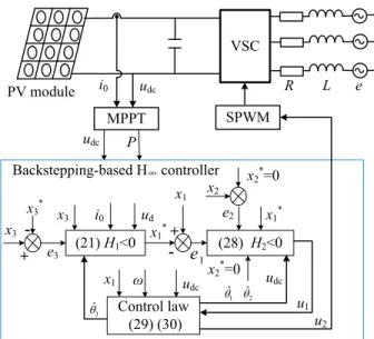
FIGURE 2. Structure of nonlinear backstepping H∞robust controller.
When the disturbanceW =0, the closed-loop error under the feedback control law is asymptotically stable [37].
˙ e1= ˙x1∗+ R Lx1−ωx2+ U1 L −bθ1−W1 ˙ e2= ˙x2∗+ R Lx2+ωx1+ U2 L −bθ2−W2 ˙ e3= ˙x3∗− 1.5ηudx1 Cx3 −I0 C −W3 (34)
Deriving (26) and substituting (29)-(31) to (34), one can get ˙ V2=e3e˙3+e1e˙1+e2e˙2+ 1 ρeθ ˙ bθ ≤ −k3e23−k1e21−k1e22<0 (35)
Since V2(e1(0),e2(0),e3(0)) is bounded, and Lyapunov
functionV2(e1(t),e2(t),e3(t)) is non-increasingly bounded,
then lim t→0 Z t 0 V2(t)dt<∞ (36)
SinceV˙2(t) is bounded,V2(t) eventually tends to 0,
accord-ing to Barbalat’s law, i.e. lim
t→0e1 = 0, lim t→0e2 = 0 and lim t→0e3 =0.
Through the above analysis, for the PV grid-connected inverter system described in (7)∼(9), the nonlinear H∞
back-stepping controller can be designed. The feedback control law (29), equation (30) and parameter update law (31) are expressed to guarantee the control system to realize the global and uniform stability. The structure diagram of the nonlinear backstepping H∞ controller is illustrated in Figure 2. The
MPPT controller is used to extract maximum power from the PV module, and the output of the MPPT controller is connected to backstepping-based H∞controller. The
equa-tion (21) and (28) are the H functions of the H∞controller,
FIGURE 3. Photograph of the experimental inverter used for testing the proposed control strategy.
TABLE 1.Experimental parameters.
the proper control variables are selected to guarantee H func-tions negative, then the system is stable. According to the control law (29) and (30), new variables are obtained to control the voltage source converter (VSC) through SPWM method.
IV. EXPERIMENTAL RESULTS
To verify the performance of the proposed controller, a test-bench of a 150kW grid-connected PV inverter is con-structed shown as Figure 3, and it includes the following equipment: programmable solar array simulation (SAS), dc power supply, PWM voltage source inverter, voltage reg-ulation transformer, AC power source, 32 fixed-point DSP TMS320F2812, and a power analyzer HIOKI 3390.
The performance of the designed controller is evaluated under five cases, and they include standard, load variation, impedance variation, presence of harmonics, and grid voltage dip. The clock frequency of the DSP is 150MHz, and other experimental parameters are shown in Table 1.
A. CASE I: CONTROLLER PERFORMANCE UNDER STANDARD ATMOSPHERIC CONDITION
In this case, the grid voltage is the standard sinusoidal wave with the constant reference current, inverter parameters and the grid impedance, and the inverter operates at the full load condition.
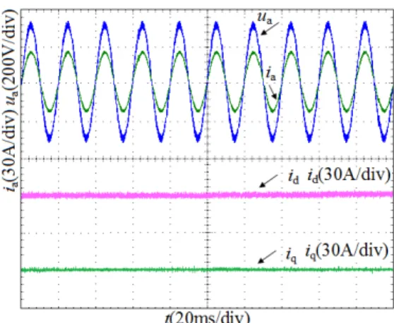
FIGURE 4. Voltage and current waveforms under H∞controller.
FIGURE 5. FFT analysis of the grid current in steady-state.
Fig. 4 represents the grid voltage, grid current and dq-component of the phase current under the nonlinear back-stepping H∞control. The grid current of the grid-connected
inverter can follow the grid voltage with no phase shift, and the grid current is also a standard sinusoidal wave. The grid-connected inverter can operate with high power factor. Figure. 5 shows the spectrum characteristic of the grid cur-rent. We can see that the proposed method has better perfor-mance, and it shows that the grid current is a sinusoidal wave, with very low harmonic content with the THD of 1.49%.
B. CASE II: CONTROLLER PERFORMANCE UNDER LOAD VARIATION
In this case, the grid voltage is the standard sinusoidal wave, with the constant inverter parameters and the grid impedance. The load of grid-connected inverter suddenly increases at 0.4s.
Figure. 6 and Figure. 7 compare the waveforms of grid voltage and grid current under nonlinear backstepping robust H∞ controller and PI controller, respectively. Under
non-linear backstepping robust H∞ control, the grid current
(d-component id) is smooth with no overshoot and fast
response when the load changes, whereas, d-componentid
controlled by PI controller shown as Figure. 6 has a large overshoot and slow dynamic response when the load changes. The nonlinear backstepping robust H∞controller shows
bet-ter dynamic performance than that of the PI controller. C. CASE III: CONTROLLER PERFORMANCE UNDER GRID IMPEDANCE VARIATION
In this case, the grid voltage is the standard sinusoidal wave, with the constant inverter parameters and constant load. The
FIGURE 6. Experimental results under H∞controller when load change.
FIGURE 7. Experimental results under PI controller when load change.
equivalent grid impedance changes from 0.8mH to 1.2mH at 0.4s.
Figure. 8 and Figure. 9 compare the waveforms of the grid voltage and grid current under the nonlinear backstep-ping H∞controller and the PI controller, respectively. From
the experimental results, it can be observed that the sys-tem based on the nonlinear backstepping H∞control shows
excellent robustness to the impedance variation. When the grid impedance changes, the proposed controller still works very well, and the grid current and voltage almost keep the sinusoidal waveforms. However, the conventional PI con-troller cannot stabilize the system and the waveforms of phase current exhibit oscillations. We can conclude that the pro-posed controller has good robustness to the grid impedance variation, while the performance of PI controller is poor when the grid impedance changes.
D. CASE IV: CONTROLLER PERFORMANCE WHEN HARMONICS INTRODUCED
The grid voltage is nonstandard voltage with 3rdand 5th har-monics involved, and the grid-connected inverter parameters and the grid impedance are constant.
The power grid simulation device is used to simulate 3rd and 5thharmonics of the power grid voltage. The grid voltage
T. Yanget al.: Adaptive Backstepping-Based H∞Robust Controller for PV Grid-Connected Inverter
FIGURE 8. Experimental results under H∞controller when grid impedance change.
FIGURE 9. Experimental results under PI controller when grid impedance change.
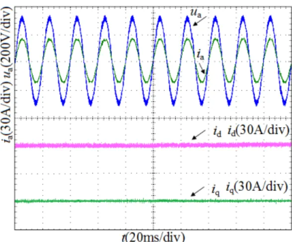
FIGURE 10. Experimental results under H∞controller when harmonic emerge in grid voltage.
and grid current under the nonlinear backstepping H∞
con-troller and PI concon-troller are compared in Figure. 10 and Figure. 11. The grid current under the nonlinear backstepping H∞ robust controller is very close to a standard sinusoidal
wave when the harmonic exists in the grid voltage, and the grid current remains good quality. However, the current
FIGURE 11. Experimental results under PI controller when harmonic emerge in grid voltage.
FIGURE 12. Experimental results under PI controller when A phase grid voltage dip of 20%.
waveform quality under PI controller is deteriorated dramat-ically, and 3rdand 5thharmonics are also deduced in the grid current due to the voltage harmonics.
E. CASE V: CONTROLLER PERFORMANCE UNDER THE GRID VOLTAGE DIP
The grid voltage is the standard sinusoidal wave, the param-eters of the inverter are fixed, and the grid voltage drops by 20% at 0.4s.
There are three control targets, including obtaining sinu-soidal and symmetrical current, removing reactive power ripple and active power ripple, when one phase voltage drops in the three-phase grid inverter [35]. Here, the standard sinu-soidal wave and symmetrical grid current are selected as the control target. Figure. 12 and Figure. 13 show the perfor-mance of the nonlinear backstepping H∞controller and PI
controller, respectively.
In Figure. 12, the grid current and grid voltage are no longer standard sinusoidal waves due to that the negative sequence component in the grid current is deduced when A-phase voltage drops. The large 2nd harmonic exists in the active and reactive current, and the waveform quality of the grid
FIGURE 13. Experimental results under H∞controller when grid voltage
dip of 20%.
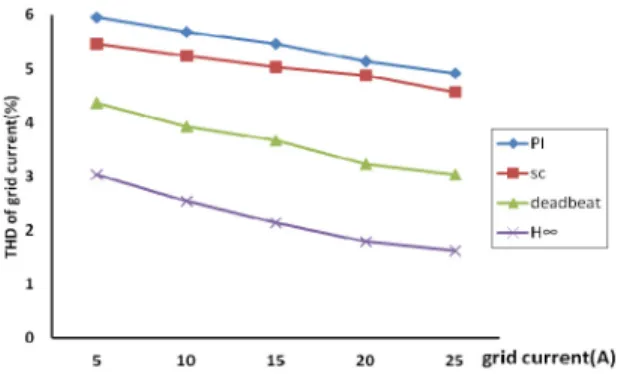
FIGURE 14. Experiment performance comparisons under steady-state.
voltage and current is poor. In contrast, the grid current and grid voltage wave under nonlinear backstepping H∞control
shown as Figure. 13 is significantly improved, and the 2nd current in d-component and q-component are dramatically suppressed.
F. PERFORMANCE COMPARISON OF CONTROLLERS To highlight advantages of the proposed algorithm, the total harmonic distortion (THD) of the grid current is selected as the index to compare the performance of nonlinear backstep-ping H∞controller, sliding mode control (SC) [9], deadbeat
control [10] and the traditional PI control under the steady-state. Figure. 14 shows the THD content of the grid current under different controllers. The nonlinear backstepping H∞
controller shows the lowest THD content at the different grid current, and other controllers, such as traditional PI controller, sliding mode controller, and deadbeat controller, have higher THD content with poor robustness.
To verify the dynamic performance of the nonlinear back-stepping H∞controller, we simulate parameters perturbation
and power grid disturbance by modifying the grid-connected inverter filter inductance and injecting 3rd harmonic in grid current. We compare the proposed controller and other three controllers; the specific performance comparison is shown in Figure.15 and Figure.16. The results show that the THD in
FIGURE 15. Experiment performance comparisons when grid impedance variation.
FIGURE 16. Experiment performance comparisons when grid current harmonic occurs.
FIGURE 17. The waveforms of Udc under different controllers.
grid current is the lowest one under nonlinear backstepping H∞controller in the presence of parameters perturbation and
grid harmonics, and the control performance is more superior than other three controllers.
To further evaluate the performance of the pro-posed method, the DC-bus voltage response of the backstepping-based H∞ controller, PI controller, sliding
mode controller, and deadbeat controller are compared in the presence of the harmonics, shown in Figure 17.
T. Yanget al.: Adaptive Backstepping-Based H∞Robust Controller for PV Grid-Connected Inverter
The DC-bus voltage controlled by backstepping-based H∞
controller has superior performance compared with other controllers. It is obvious that the DC-bus voltage changes a lot when harmonics are introduced in other controllers, and the voltage ripples of the capacitor in other controllers are bigger than backstepping-based H∞controller.
V. CONCLUSION
A novel H∞control strategy for the grid-connected inverter is
proposed in this paper. The H∞controller is derived from the
nonlinear mathematical model of the grid-connected inverter with the consideration of parameters perturbation, external disturbances and other uncertainties, which is designed by combining the backstepping controller and the robust H∞
controller.
The experimental results show that the proposed control strategy is robust to the time-varying parameters and external disturbances, and the control accuracy and power quality are also guaranteed. Compared to the traditional PI controller, sliding mode controller and deadbeat controller, the nonlin-ear backstepping H∞controller shows the best stability and
robustness under various operation conditions. REFERENCES
[1] Q. Xun and Y. Liu, ‘‘Evaluation of fluctuating voltage topology with fuel cells and supercapacitors for automotive applications,’’Int. J. Energy Res., vol. 43, no. 9, pp. 4807–4819, Jul. 2019.
[2] H. T. Nguyen, E.-K. Kim, I.-P. Kim, H. H. Choi, and J.-W. Jung, ‘‘Model predictive control with modulated optimal vector for a three-phase inverter with an LC filter,’’IEEE Trans. Power Electron., vol. 33, no. 3, pp. 2690–2703, Mar. 2018.
[3] S. Y. Gadelovits, Q.-C. Zhong, V. Kadirkamanathan, and A. Kuperman, ‘‘Uncertainty and disturbance estimator-based controller equipped with a time-delayed filter to improve the voltage quality of inverters,’’IEEE Trans. Ind. Electron., vol. 66, no. 1, pp. 459–469, Jan. 2019.
[4] H. T. Nguyen, J. Kim, and J.-W. Jung, ‘‘Improved model predictive control by robust prediction and stability-constrained finite states for three-phase inverters with an output LC filter,’’IEEE Access, vol. 7, pp. 12673–12685, Feb. 2019.
[5] Z. D. Arani, S. A. Taher, A. Ghasemi, and M. Shahidehpour, ‘‘Application of multi-resonator notch frequency control for tracking the frequency in low inertia microgrids under distorted grid conditions,’’IEEE Trans. Smart Grid, vol. 10, no. 1, pp. 337–349, Jan. 2019.
[6] J. Hu, J. Zhu, and D. G. Dorrell, ‘‘Model predictive control of grid-connected inverters for PV systems with flexible power regulation and switching frequency reduction,’’IEEE Trans. Ind. Appl., vol. 51, no. 1, pp. 587–594, Jan. 2015.
[7] M. A. Herran, J. R. Fischer, S. A. Gonzalez, M. G. Judewicz, and D. O. Carrica, ‘‘Adaptive dead-time compensation for grid-connected PWM inverters of single-stage PV systems,’’IEEE Trans. Power Electron., vol. 28, no. 6, pp. 2816–2825, Jun. 2013.
[8] T. Wang, H. Kamath, and S. Willard, ‘‘Control and optimization of grid-tied photovoltaic storage systems using model predictive control,’’IEEE Trans. Smart Grid, vol. 5, no. 2, pp. 1010–1017, Mar. 2014.
[9] R.-J. Wai, C.-Y. Lin, Y.-C. Huang, and Y.-R. Chang, ‘‘Design of high-performance stand-alone and grid-connected inverter for distributed generation applications,’’IEEE Trans. Ind. Electron., vol. 60, no. 4, pp. 1542–1555, Apr. 2013.
[10] B. Guo, M. Su, Y. Sun, H. Wang, H. Dan, Z. Tang, and B. Cheng, ‘‘A robust second-order sliding mode control for single-phase photo-voltaic grid-connected voltage source inverter,’’ IEEE Access, vol. 7, pp. 53202–53212, 2019.
[11] R. Guzman, L. G. De Vicuna, M. Castilla, J. Miret, and J. De La Hoz, ‘‘Variable structure control for three-phase LCL-filtered inverters using a reduced converter model,’’IEEE Trans. Ind. Electron., vol. 65, no. 1, pp. 5–15, Jan. 2018.
[12] T. K. S. Freddy, J.-H. Lee, H.-C. Moon, K.-B. Lee, and N. A. Rahim, ‘‘Modulation technique for single-phase transformerless photovoltaic inverters with reactive power capability,’’IEEE Trans. Ind. Electron., vol. 64, no. 9, pp. 6989–6999, Sep. 2017.
[13] M. A. Mahmud, M. J. Hossain, H. R. Pota, and N. K. Roy, ‘‘Robust nonlinear controller design for three-phase grid-connected photovoltaic systems understructure uncertainties,’’IEEE Trans. Power Del., vol. 29, no. 3, pp. 1121–1130, Mar. 2014.
[14] X. Bao, F. Zhuo, Y. Tian, and P. Tan, ‘‘Simplified feedback linearization control of three-phase photovoltaic inverter with an LCL filter,’’IEEE Trans. Power Electron., vol. 28, no. 6, pp. 2739–2752, Jun. 2013. [15] M. A. Mahmud, H. R. Pota, and M. J. Hossain, ‘‘Dynamic stability of
three-phase grid-connected photovoltaic system using zero dynamic design approach,’’IEEE J. Photovolt., vol. 2, no. 4, pp. 564–571, Oct. 2012. [16] H. M. Hasanien and M. Matar, ‘‘A fuzzy logic controller for autonomous
operation of a voltage source converter-based distributed generation sys-tem,’’IEEE Trans. Smart Grid, vol. 6, no. 1, pp. 158–165, Jan. 2015. [17] X. Fu, S. Li, M. Fairbank, D. C. Wunsch, and E. Alonso, ‘‘Training
recurrent neural networks with the Levenberg–Marquardt algorithm for optimal control of a grid-connected converter,’’IEEE Trans. Neural Netw. Learn. Syst., vol. 26, no. 9, pp. 1900–1912, Sep. 2015.
[18] P. K. Ray, S. R. Das, and A. Mohanty, ‘‘Fuzzy-controller-designed-PV-based custom power device for power quality enhancement,’’IEEE Trans. Energy Convers., vol. 34, no. 1, pp. 405–414, Mar. 2019.
[19] J. Fei, Y. Chu, and S. Hou, ‘‘A backstepping neural global sliding mode control using fuzzy approximator for three-phase active power filter,’’
IEEE Access, vol. 5, pp. 16021–16032, 2017.
[20] Q.-C. Zhong and T. Hornik, ‘‘Cascaded current-voltage control to improve the power quality for a grid-connected inverter with a local load,’’IEEE Trans. Ind. Electron., vol. 60, no. 4, pp. 1344–1355, Apr. 2013. [21] P. Li and Z. H. Yin, ‘‘Robust control on flexible grid-connection of
pho-tovoltaic generation system in microgrid based onµ-synthesis method,’’
Proc. CSEE, vol. 34, no. 28, pp. 4847–4854, 2014.
[22] J.-W. Jung, N. T.-T. Vu, D. Q. Dang, T. D. Do, Y.-S. Choi, and H. H. Choi, ‘‘A three-phase inverter for a standalone distributed generation system: Adaptive voltage control design and stability analysis,’’IEEE Trans. Energy Convers., vol. 29, no. 1, pp. 46–56, Mar. 2014.
[23] S. Yang, Q. Lei, F. Z. Peng, and Z. Qian, ‘‘A robust control scheme for grid-connected voltage-source inverters,’’IEEE Trans. Ind. Electron., vol. 58, no. 1, pp. 202–212, Jan. 2011.
[24] T. Hornik and Q.-C. Zhong, ‘‘A current-control strategy for voltage-source inverters in microgrids based onH∞and repetitive control,’’IEEE Trans.
Power Electron., vol. 26, no. 3, pp. 943–952, Mar. 2011.
[25] Y. Wei Li, D. M. Vilathgamuwa, F. Blaabjerg, and P. C. Loh, ‘‘A robust control scheme for medium-voltage-level DVR implementation,’’IEEE Trans. Ind. Electron., vol. 54, no. 4, pp. 2249–2261, Aug. 2007. [26] J. Chen, F. Yang, and Q.-L. Han, ‘‘Model-free predictive H∞control
for grid-connected solar power generation systems,’’IEEE Trans. Control Syst. Technol., vol. 22, no. 5, pp. 2039–2047, Sep. 2014.
[27] A. Kahrobaeian and Y. A.-R.-I. Mohamed, ‘‘Robust single-loop direct current control of LCL-filtered converter-based DG units in grid-connected and autonomous microgrid modes,’’IEEE Trans. Power Electron., vol. 29, no. 10, pp. 5605–5619, Oct. 2014.
[28] G. Weiss, Q. C. Zhong, T. C. Green, and J. Liang, ‘‘H∞repetitive control of
DC-AC converters in microgrids,’’IEEE Trans. Power Electron., vol. 19, no. 1, pp. 219–230, Jan. Jan. 2004.
[29] J. Liu and K. W. E. Cheng, ‘‘µ-based robust controller design of LCLC res-onant inverter for high-frequency power distribution system,’’IET Power Electron., vol. 6, no. 4, pp. 652–662, Apr. 2013.
[30] Z. Chen, B. Yao, and Q. Wang, ‘‘µ-synthesis based adaptive robust control of linear-motor-driven stages with high-frequency flexible modes,’’IFAC Proc. Volumes, vol. 46, no. 5, pp. 207–213, 2013.
[31] Z. Chen, B. Yao, and Q. Wang, ‘‘Adaptive robust precision motion control of linear motors with integrated compensation of nonlinearities and bearing flexible modes,’’IEEE Trans. Ind. Informat., vol. 9, no. 2, pp. 965–973, May 2013.
[32] R.-J. Wai and H.-H. Chang, ‘‘Backstepping wavelet neural network control for indirect field-oriented induction motor drive,’’IEEE Trans. Neural Netw., vol. 15, no. 2, pp. 367–382, Mar. 2004.
[33] S. W. Mei, T. L. Shen, and K. Z. Liu,Modern Robust Control Theory and Applications, 2nd ed. Beijing, China: Tsinghua University press, 2003. [34] F. F. M. El-Sousy, ‘‘Hybrid H∞-based wavelet-neural-network tracking
control for permanent-magnet synchronous motor servo drives,’’IEEE Trans. Ind. Electron., vol. 57, no. 9, pp. 3157–3166, Sep. 2010.
[35] L. Shang, D. Sun, and J. Hu, ‘‘Sliding-mode-based direct power control of grid-connected voltage-sourced inverters under unbalanced network conditions,’’IET Power Electron., vol. 4, no. 5, p. 570, 2011.
[36] A. Lari, A. Khosravi, and F. Rajabi, ‘‘Controller design based onµanalysis and PSO algorithm,’’ISA Trans., vol. 53, no. 2, pp. 517–523, Mar. 2014. [37] M. F. Firuzi, A. Roosta, and M. Gitizadeh, ‘‘Stability analysis and
decen-tralized control of inverter-based AC microgrid,’’Protection Control Mod. Power Syst., vol. 4, no. 6, pp. 1–24, 2019.
TONGGUANG YANGreceived the Ph.D. degree from Central South University, China, in 2013. He is currently a Professor with the School of Mechanical and Electrical Engineering, Hunan City University. His current research interests include grid-connected inverters control for new energy and fault diagnosis for induction motor.
ZHENHUA CAIreceived the masters’ degree from Hunan University, China, in 2013. He is currently with the School of Mechanical and Electrical Engineering, Hunan City University. His current research fields include power system informatiza-tion, planning, and new energy.
QIAN XUN received the B.Eng. degree from Hohai University, China, in 2012, and the M.Sc. degree from the Nanjing University of Aeronautics and Astronautics, China, in 2015. She is currently pursuing the Ph.D. degree with the Chalmers University of Technology, Sweden. She worked as a Lecturer at Huzhou University, China, for two years. Her research interests include driv-etrain design for fuel cell electric vehicle and grid-connected inverters control.