Western University
Scholarship@Western
Electrical and Computer Engineering Publications
Electrical and Computer Engineering Department
2016
CEPSim: Modelling and Simulation of Complex
Event Processing Systems in Cloud Environments
Wilson A. Higashino
Western University, [email protected]
Miriam AM Capretz
Western UniversityLuiz F. Bittencourt
University of Campinas, [email protected]
Follow this and additional works at:
https://ir.lib.uwo.ca/electricalpub
Part of the
Computer Engineering Commons, and the
Electrical and Computer Engineering
Commons
Citation of this paper:
Higashino, Wilson A.; Capretz, Miriam AM; and Bittencourt, Luiz F., "CEPSim: Modelling and Simulation of Complex Event Processing Systems in Cloud Environments" (2016).Electrical and Computer Engineering Publications. 75.
CEPSim: A Simulator for Cloud-Based Complex
Event Processing
Wilson A. Higashino
⇤†, Miriam A. M. Capretz
⇤, Luiz F. Bittencourt
† ⇤Dept. of Electrical and Computer EngineeringWestern University, London, Canada Email:{whigashi, mcapretz}@uwo.ca
†Instituto de Computac¸˜ao
Universidade Estadual de Campinas, Campinas, Brazil Email:{wah, bit}@ic.unicamp.br
Abstract—As one of the Vs defining Big Data, data velocity brings many new challenges to traditional data processing approaches. The adoption of cloud environments in complex event processing (CEP) systems is a recent architectural style that aims to overcome these challenges. Validating cloud-based CEP systems at the required Big Data scale, however, is often a laborious, error-prone, and expensive task. This article presents
CEPSim, a new simulator that has been developed to facilitate this validation process. CEPSim extends CloudSim, an existing cloud simulator, with an application model based on directed acyclic graphs that is used to represent continuous CEP queries. Once defined, the queries can be simulated in different cloud environments under diverse load conditions. Moreover,CEPSim
is also customizable with different operator placement and scheduling strategies. These features enable researchers and system architects to experiment with different configurations and strategies and to promote research in this field. Experimental results show that CEPSim can successfully simulate existing cloud-based CEP systems.
Index Terms—complex event processing; cloud computing; simulation; Big Data.
I. INTRODUCTION
Recent trends in Web technologies and the proliferation of sensor networks and mobile devices have created massive amounts of data that pose many new challenges to traditional data processing approaches. This new Big Data world is often characterized by 4 Vs that identify these challenges [1]: volume, velocity, variety, and veracity.
The velocity dimension of Big Data refers to how fast data are generated and how fast they must be processed. Therefore, handling velocity requires applications with online processing capabilities of fast and continuous streams of data. From the business perspective, the goal is to obtain insights from these streams and to enable prompt reaction to them [2]. Among the technologies that can be used to achieve this goal, Complex Event Processing (CEP) is one of the most prominent.
CEP-based systems interpret input data as a stream of events and accept user definitions of queries (rules) to derive semantically enriched “complex” events from a series of simpler events. These complex events can then be used to trigger actions or be fed back to the system and potentially originate other events. Because of the enormous scale as-sociated with Big Data, traditional CEP systems have been
replaced by newer systems that leverage cloud environments to provide the low latency and scalability required by modern applications [3], [4], [5].
Development of efficient query distribution and scheduling strategies is essential to the good performance of cloud-based CEP systems. Nevertheless, validating these strategies at the required Big Data scale is a research problem per se. For instance, setting up large cloud deployments is a laborious and error-prone process. Moreover, cloud environments are subject to variations that make it very difficult to reproduce the environment and conditions of an experiment [6]. Finally, the financial cost and time required by these experiments is often very high and may hamper their execution.
A common approach used to overcome these challenges is to use simulators. Many areas of computer science have been using simulators as a fast and efficient way to experiment with different strategies and algorithms without incurring the effort of running large-scale experiments. This approach has also been applied to cloud computing research, as confirmed by the reasonable number of cloud environment simulators avail-able [7], [8], [9]. Nevertheless, these existing simulators often assume a simplistic application model that cannot represent CEP applications running in the cloud.
This article presents a new simulator calledCEPSim, which can be used to simulate CEP applications in multi-cloud environments. CEPSimextends CloudSim[8] with a new ap-plication model based on directed acyclic graphs (DAGs) that represent continuous queries processing fast streams of data. UsingCEPSim, execution of these queries can be simulated in different environments, including private, public, and multiple clouds. In addition, CEPSim can also be customized with different operator placement and scheduling strategies. These features enable researchers and system architects to experi-ment quickly with different configurations and strategies, thus encouraging research in this field.
This article is organized as follows: Section II presents back-ground information and related work. Section III discusses the design ofCEPSim, and Section IV examines how it has been integrated withCloudSim. Experimental results are shown in Section V, followed by conclusions in Section VI.
W.A. Higashino, M.A.M. Capretz, L.F. Bittencourt, “CEPSim: A Simulator for Cloud-Based Complex Event Processing”, in Proc. of the 4th Int. Congress on Big Data (IEEE BigData Congress 2015), 2015, pp. 182-190..
Copyright: http://www.ieee.org/documents/ieeecopyrightform.pdf http://dx.doi.org/10.1109/BigDataCongress.2015.34
II. RELATEDWORK
A. Complex Event Processing
The basis of CEP was established by the work of Luckham on Rapide [10] and later on in his book [11]. At about the same time, the database community developed the first classical Data Stream Processing (DSP) systems, such as
Aurora [12] and STREAM [13]. CEP and DSP technologies share related goals, as both are concerned with processing continuous data flows coming from distributed sources to obtain timely responses to queries [14].
This work adopts a terminology based on the Event Process-ing Technical Society (EPTS) glossary [15], which originated from the CEP literature. According to the glossary definitions, CEP can be considered a superset of DSP.
B. CEP Query Languages
In CEP systems, users create queries (or rules) that specify how to process the input event streams and derive “complex events”. These queries have usually been defined by means of proprietary languages such as Aurora Stream Query Algebra (SQuAl) [12] and CQL [13].
This research uses Directed Acyclic Graphs (DAG) as a language-agnostic representation of CEP queries, which is a natural choice corroborated by many studies in the liter-ature. For instance, many CEP systems also use DAGs to represent user queries. This is the case with Aurora [12],
StreamCloud [5], Storm[16], and many others.
Systems that use declarative query languages, on the other hand, transform user queries into query plans to make them “executable”, which often leads to structures that can be mapped into DAGs. The STREAM system and the CQL language [13] are examples that use this approach, as well as theTimeStream[4] project. Finally, some systems are based on pattern-based query languages that cannot be directly mapped to DAGs. Even in this case, however, previous studies [17] have shown that is possible to transform these queries into DAG structures.
C. CEP in the Cloud
The recent emergence of cloud computing has been strongly shaping the CEP landscape. For instance, TimeStream[4] and
StreamCloud [5] are CEP systems that use cloud infrastruc-tures as their runtime environments.
Similarly, the discussion around Big Data, and, more specif-ically the rise of the MapReduce platform [18], have also had a great impact on CEP. The prevalence and success of MapReduce has motivated many researchers to work on systems that leverage some of its advantages while at the same time trying to overcome its limitations when applied to low-latency processing. StreamMapReduce [19], M3 [20], and Twitter’sStorm[16] are examples of MapReduce-inspired systems aimed at stream processing.
D. Simulator
The use of simulation in research of large-scale cloud applications has motivated the development of a number of simulators such as GreenCloud [7], CloudSim [8], and
iCanCloud[9]. None of these, however, can effectively model CEP applications.
GreenCloud [7] targets packet-level simulation and energy consumption of network equipment, which are not the focus of this research.
CloudSim [8], on the other hand, is a well-known cloud computing simulator that can represent various types of envi-ronments, including private, public and multiple clouds. It pro-vides customizable virtual machine allocation and provisioning policies and also supports a number of energy consumption and network models. The major drawback of CloudSim is its simple application model, which is more appropriate for simulation of independent batch jobs. This work circumvents this limitation with a new model based on DAGs.
Because of its flexibility, CloudSim has originated many different extensions in the literature [6], [21], [22]. Garg and Buyya [6] createdNetworkCloudSim, which extendsCloudSim
with a three-tier network model. Gu´erout et al. [21], on the other hand, focussed on implementing the DVFS model on CloudSim. Finally, Grozev and Buyya [22] presented a model for three-tier Web applications and incorporated it into
CloudSim. These extensions are orthogonal to those presented in this paper because they do not focus on CEP.
TheiCanCloudsimulator [9] is similar to CloudSim, but it can also parallelize simulations and it has a GUI to interact with the simulator. The choice of CloudSim over iCanCloud
in this article was motivated by its more mature codebase, the authors’ previous experience, and the larger number of extensions available.
III. CEPSIM
CEPSim has been built to simulate multiple CEP queries running on multiple virtual machines deployed in cloud envi-ronments. Its main design principles are:
• Generality: it can simulate different CEP cloud-based
systems independently of query definition languages and platform specificities;
• Extensibility: it can be extended with different operator
placement, operator scheduling, and load shedding algo-rithms;
• Multi-Cloud: it can run the simulation on multiple clouds
at the same time;
• Self-containment: it can be integrated with cloud
simula-tors other thanCloudSim.
• Reuse: it can reuse capabilities that are present in
CloudSimand comparable simulators.
Figure 1 shows a component view ofCEPSim. TheCEPSim Core component, described in this section, is responsible for most of the CEP-related logic whereas the CloudSim com-ponent manages the simulation infrastructure and execution. The CEPSim Integration component implements the pieces
Fig. 1. CEPSimcomponents.
Fig. 2. Query example.
necessary to integrate both and is described in Section IV. This design guarantees a loose coupling betweenCEPSimand
CloudSimand enables future integration with other simulators. The CEPSim Core is composed of four main subcompo-nents: the query model, which contains the base classes used to describe queries; the query executor, which implements most of the simulation logic; logging, which provides logging facilities for the simulation; and metrics, which calculate the metrics of interest to the simulator. The next subsections detail these subcomponents.
A. Query model
In CEPSim, each user-defined query Q is represented by a directed acyclic graph (DAG) GQ = (VQ, EQ), in which
the vertices VQ represent query elements and the edges EQ
represent event streams flowing from one element to another. Figure 2 shows an example of a queryQ. The numbers on the event producers represent their event generation rates, whereas the numbers on the edges are their selectivities. These concepts are described in detail in the following paragraphs.
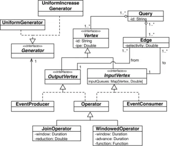
Figure 3 shows a diagram of the classes used to represent query graphs in CEPSim. The V ertex class
is at the top level of the hierarchy, and two subtypes of this class have been identified: OutputV ertex and InputV ertex. The former represents vertices with
outgo-ing edges, and the latter represents vertices with incomoutgo-ing edges. EventP roducer describes event producers (sources)
and therefore is a subclass of OutputV ertexonly. Similarly,
EventConsumer characterizes event consumers (sinks) and is a subclass of InputV ertex. Finally, an Operator is both an OutputV ertex and an InputV ertex because it receives events from some vertices and sends them to others.
1) Vertex: Every V ertex has a unique identifier (id) and an attribute instructions per event (ipe), which represents the number of CPU instructions needed to process a single event. For EventP roducers, this attribute estimates the number of
instructions required to take events from the system input
Fig. 3. CEPSimclass diagram.
queues and forward them to query execution. A similar observation applies to EventConsumers: the ipe attribute
measures only the effort required to forward the resulting events to external systems or servers that effectively consume the events.
2) Edge: A graphEdgeconnects an originOutputV ertex
with a targetInputV ertex, and has an associatedselectivity
attribute. Theselectivity determines how many of the events
that are input to the origin vertex are sent to the target. For example, the outgoing edges of operators that only transform events have selectivity = 1, whereas operators that filter or
combine events haveselectivity <1.
3) Query: A Query is defined as a simple composition of vertices and their associated edges. Similarly to vertices, a query also has anidwhich uniquely identifies it in the system.
4) Operator: The base Operator class can be used to
simulate stateless operators. For example, an Aurora filter is an operator that routes events to alternative outputs based on event attributes [12]. This operator is represented inCEPSim
by anOperatorinstanceopconnected tomneighboursopm.
Each edge (op!opm) has a selectivity that determines the
percentage of allopinput events sent toopm.
To simulate stateful operators, two Operator subclasses have been created:JoinOperatorandW indowedOperator. AJoinOperatoris similar to a database join in the sense
that it also findsn-tuples of events that satisfy some condition.
A JoinOperator has two parameters: a window, which
controls the window size used to search for then-tuples, and a reductionfactor that determines the percentage of all possible n-tuples that satisfy the join condition. For example: ifop is
defined as a join operator with two inputs and a window size of one minute, and if 100 events arrived at each input during the last minute, then there are 10 thousand event pairs that could satisfy the join. Thereductionfactor controls the number of these pairs that are sent to theopoutput.
Fig. 4. Window attributes.
simulate operators that process windows of events and com-bine them in some manner. Typical examples are aggregation operators that count events or calculate the average value of attributes. W indowedOperators behaviour is determined by
three main attributes: a window size, an advance duration,
and a combination f unction.
Figure 4 illustrates the window and advance concepts.
The window specifies the period of time from which the events are taken, and the advance duration defines how the window slides when the previous window closes. Finally, the combinationf unctionis defined as:
f :Rm0!R 0 (1)
wheremis the number of operator predecessors. The function
regulates the number of events that are sent to the output given the number of events accumulated in the input. Commonly, it can be defined as a constantf(x) = 1, meaning that for each
window, only one event is generated (e.g., for counting events).
5) Generator: Every EventP roducer is associated with a Generator instance, which defines the number of events generated per simulation interval. CEPSimcurrently contains two different implementations:
• U nif ormGenerator: generates a constant number of
events per simulation interval;
• U nif ormIncreaseGenerator: generates a uniformly
increasing number of events until it reaches a maximum rate. After this point, this maximum rate is maintained until the end of the simulation.
Other type of generators can be easily added toCEPSimby creating extra Generatorimplementations.
B. Query executor
The main idea of the CEPSim simulation algorithm is to keep with each query an internal state representing its execution and, at equally spaced simulation ticks, to update the state of all active queries.
The state of a query on a CEP system is roughly determined by a queue of events associated with each operator’s in-coming edge (attribute inputQueuesfrom the InputV ertex
interface). As a simulator, CEPSim only tracks the number of events in each queue and does not handle real events. Therefore, to “enqueue” events is equivalent to adding to the queue size counter the number of incoming events. Moreover,
CEPSimalways represents the number of processed events as a floating-point number, which enables “partially processed”
Fig. 5. Query execution class diagram.
Fig. 6. Placement definitions.
events to be exchanged between operators. This characteristic is especially useful to simulate complex operators that require more than one simulation tick to process an event. For exam-ple, an operator that requires five simulation ticks to generate an output can be simulated by generating0.2events per tick.
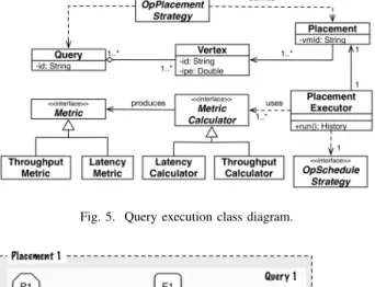
Figure 5 shows the main classes and interfaces developed for query simulation. The first step in a simulation is to define a set of queryP lacements, in which each P lacementmaps
a set of vertices to the virtual machine on which they will run. Note that the vertices from a query can be mapped to more than one virtual machine, which implies distributed query execution. In addition, a placement can also contain vertices from more than one query. Figure 6 illustrates this concept:
P lacement1 maps all vertices fromQuery1 and some from
Query2 toV m1, whereas P lacement2 maps the remaining
Query2 vertices to V m2. Defining placements for a set of
queries is an instance of the operator placement problem, as defined by Lakshmanan et al. [23]. CEPSim is pluggable and can incorporate different placement algorithms by using alternative implementations of the OpP lacementStrategy
interface.
The execution of eachP lacementis handled by an instance
of the P lacementExecutor class, which encapsulates most
of the simulation logic. The class has three main methods that constitute theP lacementlifecycle: init,run, andf inish.
Theinitmethod simply iterates over all vertices belonging to theP lacementand initializes each one, whereas thef inish
Fig. 7. Execution of a simulation tick.
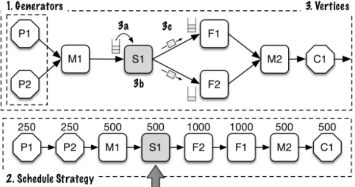
The run method is invoked at each simulation tick and
receives two main parameters: the number of CPU instructions that the placement can use at that tick, and the clock time at which the method has been invoked. Figure 7 shows a schematic representation of the steps executed in a simulation tick, which are:
1) All Generators associated withEventP roducers from the placement are activated to determine the number of events that have been generated from the last simulation tick to the current one;
2) The OpScheduleStrategy associated with the P lacementExecutor is invoked to define the order
in which the vertices will be run and the number of instructions allocated to each vertex. The default scheduling strategy sorts the placement vertices according to a topological order and allocates a number of instructions proportional to the vertices’ ipe
attribute. This strategy ensures that each vertex has the chance to process the same number of events at each iteration. Nevertheless, other strategies can also be used by providing alternative OpScheduleStrategy
implementations. The bottom of Figure 7 shows an example of a vertex processing sequence determined by a schedule strategy alongside the number of instructions allocated to each vertex.
3) Finally, all vertices are traversed and executed according to the specified order. Each vertex execution is also a multi-step process:
a) The events in the input queues are consumed (step 3a). For EventP roducer vertices, the generators are
considered as the incoming neighbours. The total number of events consumed is obtained by dividing the number of allocated instructions by the operator ipe. If the
operator has more than one input queue, then this total is distributed proportionally to the size of the queues. b) The operator is “executed”, and the output events are
generated (step 3b). The number of generated outputs depends on the operator implementation, as described in Section III-A.
c) The generated events are sent to the vertex successors and enqueued in their input queues (step 3c).
TABLE I
CEPSimSIMULATION PARAMETERS.
Name Description
Simulation interval Length of the simulation tick
Placement strategy Algorithm that maps query vertices to vir-tual machines
Scheduling strategy (per placement) Algorithm that defines the order on which vertices are traversed and the number of instructions allocated to each Generator (per event producer) Function that charac-terizes the rate at which input events are generated
Queue size (per vertex) Input queue size
These steps are repeated for all vertices in the sequence returned by the scheduling strategy.
Bounded queues: Most CEP systems limit the size of operator queues to avoid memory overflow and to maintain overall system performance. Because of this characteristic,
CEPSimalso supports the definition of bounded input queues. When using this feature, it is necessary to define the behaviour of the system when new events arrive at an already full queue. Currently, CEPSim supports only the application of
backpressureto the incoming neighbours.
When usingbackpressure, operators inform their predeces-sors about the maximum number of events accepted for the next iteration at the end of every simulation tick. Then the predecessors limit their output on the next tick (if needed). Nevertheless, when an operator limits its output, it may also accumulate events in its own input queue and, consequently, applybackpressureon its own set of predecessors. Ultimately, the backpressure arrives at the event producer generators, which may also choose to discard extraneous events or ac-cumulate them in their own queues.
Table I summarizes the parameters and policies that can be customized by the user and affect the simulation behaviour. The table, however, contains onlyCEPSimspecific parameters. Other aspects of the simulation, such as datacentre characteris-tics and resource allocation policies are defined byCloudSim, and their description is out of the scope of this article.
C. Logging
In therunmethod,CEPSimmaintains a log of all important events occurring during the simulation. Formally, this log is defined for each placement as a list of three types of entries: 1)
Processed, representing events processed by a vertex; 2)Sent, representing events sent to a remote vertex; and 3)Received, representing events received from a remote vertex.
Each log entry has the following attributes: 1) t, the sim-ulation tick number; 2) ts, a timestamp measuring the wall clock time elapsed since the beginning of the simulation; 3)id, the vertex identifier; and 4) processed, the number of events processed, sent, or received by the vertex.Senttuples also have adestattribute containing the vertex identifier to which events have been sent, and Received tuples have an orig attribute
D. Metrics
One of the most important parts of a simulator is how the metrics of interest are calculated. CEPSimhas an extensible metrics framework which enables new metrics to be added by creating implementations of theM etricCalculator interface
(see Figure 5). These implementations are registered on the
P lacementExecutor before the simulation and can measure
any aspect of the simulation state. Because of their importance,
CEPSim provides built-in implementation for two metrics:
query latency andquery throughput.
The query latency metric is calculated for each consumer
c and measures the average number of milliseconds from the
moment an event arrives at the query to the moment it is consumed byc. Latency calculation is based on the following procedure:
• Each queue Uuv connecting a vertex u to a vertex v
has an associated timestamp tsq(Uuv). This timestamp
measures the average simulation time at which the events have arrived at the queue. Ifv is an event producer, then uis the generator connected to the producer;
• Each queue Uuv also has an associated latency lq(Uuv)
that measures the average latency of events from their producers to vertex v. If v is an event producer, then
lq(Uuv) = 0;
• When a vertex vemits a new set of eventsEvt at timet,
the timestamp and latency of these events are calculated as: tse(Evt) = P i2pred(v)tsq(Uiv)·p(Uiv, Evt) P i2pred(v)p(Uiv, Evt) (2) le(Evt) = P i2pred(v)lq(Uiv)·p(Uiv, Evt) P i2pred(v)p(Uiv, Etv) +(t tse(Evt)) (3) wherepred(v)is the set of predecessor vertices ofvand
p(Uiv, Evt)is the number of events consumed from queue
Uiv to produceEvt.
• For each queue Uvw that succeeds v, the timestamp
tsq(Uvw)and latencylq(Uvw) are updated as:
tsq(Uvw) = | Et v| ·t+|Uvw| ·tsq(Uvw) |Et v|+|Uvw| (4) lq(Uvw) = | Et v| ·le(Evt) +|Uvw| ·lq(Uvw) |Et v|+|Uvw| (5) where |Et
v| is the number of events inEvt and |Uvw| is
the number of events in queue Uvw.
• The latency of a consumercis simply the average latency
of all events consumed by c: latency(c) =X
t2T
le(Ect)/|T| (6)
whereT is the set of all timestamps whenchas consumed
some event.
Query throughput is also calculated for each consumer c
as the average number of events processed per second during
its lifespan. Formally, the following procedure is executed to calculate this metric:
• Given a query Q, a consumer c has an associated total
tl(c, pk)for each producerpk 2Qp, whereQp is the set
of all producers fromQ. This value is an estimate of the total number of events from pk that had to be produced
to generate coutputs;
• Each queueUuv connecting a vertexuto a vertexvalso
has an associated total tlq(Uuv, pk) for each producer
pk 2 Qp. This quantity measures the number of events
from pk that had to be produced to originate the events
currently in queueUuv.
• When a vertex v emits a new set of events Evt at time
t, a total for these events and for each producer pk is
calculated as: tle(Evt, pk) = X i2pred(v) ✓p(U iv, Evt) |Uiv| · tlq(Uiv, pk) ◆ (7)
• For each vertex w that succeeds v and each producer
pk 2Qp, the totaltlq(Uvw, pk)is updated as:
tlq(Uvw, pk) =tlq(Uvw, pk) +tle(Evt, pk) (8)
• When a consumercconsumes a set of eventsEvt, its total
for each producerpk is updated as:
tl(c, pk) =tl(c, pk) +tle(Evt, pk) (9)
• Finally, the throughput of consumer cis calculated as:
throughput(c) =✓ X pk2Qp tl(c, pk) |paths(pk, c)| ◆ /Q.time (10) where|paths(pk, c)|represents the number of paths from
producer pk to consumer c and Q.time is the query
execution time in seconds.
IV. CLOUDSIMINTEGRATION
In accordance with the reuse design principle, CEPSim
leverages many functionalities provided byCloudSimto enable the simulation of CEP queries. For instance, CloudSim is used to define the cloud computing environments in which the simulations are run and to select and customize resource allocation algorithms used in these environments. These al-gorithms implement different strategies for assigning physical servers and CPUs to virtual machines, and for splitting the available processing power among VM processes. In addition,
CloudSimalso provides a discrete simulation framework that is used to control theCEPSimmain simulation loop.
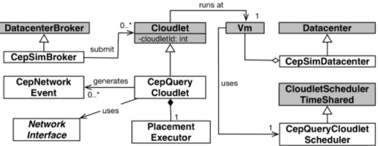
This section describes howCloudSimhas been extended and integrated with the CEPSim core described in the preceding section. The main parts of this extension are depicted in the class diagram of Figure 8. Classes shown in grey are part of CloudSim, whereas those shown in white are new classes created to enable the integration.
Fig. 8. CEPSimintegration withCloudSim.
A. Standalone queries
First, the CloudSim simulator was extended to simulate standalone CEP queries running on a single server. The main part of this extension is the CepQueryCloudlet class, a Cloudlet specialization that encapsulates the CEP placement
executor described in Section III-B.
In CloudSim, a Cloudlet represents a workload that is submitted and processed by the cloud virtual machines [8]. Normally, a Cloudlet represents a finite computation with
a length pre-defined by a fixed number of instructions. It is assumed that these computations are independent and there is no visibility of the Cloudlets internal state other than its
expected finish time.
CEP queries, on the other hand, are continuous computa-tions that run indefinitely or for a specific period of time. Moreover, tracking queries internal state during simulation is essential to the analysis of any given CEP system. For example, an input queue that is always full indicates that an operator cannot keep up with the incoming event rate. TheCepQueryCloudletclass implements these features, but
because it is aCloudletspecialization it can still be managed
by CloudSimsimulation engine.
During the simulation, aCepQueryCloudletorchestrates a P lacementExecutorexecution by invoking therunlifecycle
method at each simulation tick. Both parameters needed by the
runmethod, the number of available CPU instructions and the
clock time, are provided by the CloudSimsimulation engine. The other main classes created for the integration are:
• CepSimBroker: a broker acts as a mediator
between SaaS and cloud providers [8]. The
CepSimBroker extends the CloudSim broker to
handle CepQueryCloudlets. It also keeps a mapping
of all vertices to the VMs to which they have been allocated.
• CepSimDatacenter: this datacentre specialization
guar-antees that a simulation event is generated at equally spaced intervals. CloudSimupdates the state of all sim-ulated entities in response to each of these events. Therefore, the shorter the interval, the more accurate the simulation will be, but at a higher computation cost.
• CepQueryCloudletScheduler: a scheduler defines how
the processing power of a VM is shared among all cloudlets allocated to it [8]. This research extends the
Fig. 9. Storm topology.
time-sharing policy, in which each cloudlet receives a time slice of the VM cores. This policy has been chosen because it is a natural model that reflects current operating system implementations. The extension had to be created because the regular policy handles neither infinite nor duration-based cloudlets.
B. Networked queries
CloudSim has also been extended to simulate networked (distributed) CEP queries. This extension works as follows:
1) At the end of eachP lacementExecutorsimulation tick,
the CepQueryCloudlet class checks the P lacement
log for Sent log entries. For each entry found, the
CepQueryCloudletinvokes the sendM essage method
at theN etworkInterf ace.
2) ThesendM essagemethod calculates the delay in
send-ing the events from the target to the destination vertex and schedules a new simulation event at the calculated timestamp. When this simulation event is processed, the sent events are enqueued into the destination vertex input queue.
3) At the next simulation tick, the enqueued events are processed by the correspondingP lacementExecutor.
Note that CloudSim includes basic network simulation capabilities that are used to calculate the network delay. Nevertheless, more advanced network simulations can be used by creating alternative implementations ofNetworkInterface.
V. EXPERIMENTS
This section describes the experiments that have been per-formed to validate the CEPSim simulator. The experiments compare the latency and throughput metrics obtained by running queries on a real CEP / stream processing system (Apache Storm [16]) and by simulating them onCEPSim.
Figure 9 shows the Storm query (topology) used in the experiment. Aspoutin the Storm terminology is equivalent to an event producer, whereas aboltis equivalent to an operator. An event consumer in Storm is simply aboltwith no outgoing edges. The query in the figure is a use case from Powersmiths’ WOW system [24], a sustainability management platform that draws on live measurements of building systems to support energy management.
There are three main steps in this query: the first bolt detects and filters anomalous sensor readings, the second bolt groups readings into windows of 15 seconds and calculates the average, and the final bolt stores the calculated average in a database. The query has been implemented using Java according to the Storm APIs. In addition, it has also been instrumented to obtain reliable latency and throughput mea-surements.
TABLE II
STORM CLUSTER SPECIFICATION.
# CPU Mem. Description
1 1 core - Intel Xeon E5-2630 2.6 GHz 512 MB zookeeper 2 1 core - Intel Xeon E5-2630 2.6 GHz 768 MB nimbus 3 1 core - Intel Xeon E5-2630 2.6 GHz 2048 MB workers
Table II describes the cluster of virtual machines (VMs) used in the experiments. VMs #1 and #2 run zookeeper and
nimbus, which coordinates the cluster communication and assigns tasks to workers, respectively. The worker VM is the one which effectively executes the queries. All VMs were deployed on the same physical server (12 cores Intel Xeon E5-2630, 2.6Ghz / 96GB RAM).
A. Setup
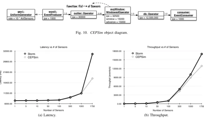
The first step of the experiment was to implement the Storm query in the CEPSim model. The mapping of Storm queries to CEPSimis straightforward because both use DAGs as the underlying query model. As an example, Figure 10 depicts an object diagram of the query as implemented in CEPSim. Storm’sspouts andbolts are mapped toEventP roducerand Operatorinstances respectively. More specifically, the second
bolt is mapped to an instance of the W indowedOperator
class because it uses the rolling window concept.
Each link connecting two objects in Figure 10 represents an edge of the query graph and is annotated with the corre-sponding edge selectivity. For example, the operator outlier
is connected to avgW indow with selectivity = 0.95. This selectivity represents the fact that only 95% of the events processed by outlier are sent to avgW indow (the other 5% are anomalies). Finally, each vertex of the graph also contains the ipe attribute, which estimates the number of instructions needed to process an event. These values were obtained beforehand in a separate experiment which estimated the maximum throughput for each Storm operator. Based on estimations of the processor MIPS and the maximum operator throughput, it is possible to roughly calculate the number of instructions required to process each event.
Following, CloudSim was used to create a simulation en-vironment as close as possible to the Storm cluster servers. Processor capacity has been estimated as 2500 MIPS. A
simulation interval of 10 ms was used to achieve higher
precision.
B. Results
Figure 11 summarizes the results of the experiment. The first graph plots the query latency as a function of the number of sensors sending data to the query. The second graph is similar and depicts the query throughput as a function of the number of sensors.RandomSensorSpoutfrom the Storm query was implemented to send 10 readings each second per sensor, of which 5% are anomalies.
The Storm query was run for every number of sensors for 30 minutes. The values shown in the graphics are the
average latency (throughput) for the last 20minutes.CEPSim
results were simulated only once, because the results are deterministic.
Generally speaking, CEPSim achieved very high accuracy for latency and good accuracy for throughput. The latency error was less than2%up to1000sensors, and even though the
error was higher at1750 sensors,CEPSimcorrectly captured
the general shape of the curve and the fact that the query started to overload at this point.
CEPSim also accurately calculated the query throughput, achieving 0% error from1 to100 sensors and approximately 10% for 500 and 1000 sensors. The throughput accuracy diminished at higher generation rates, but once againCEPSim
could show the performance degradation at 1750sensors.
Further analysis concluded that this divergence in metric values has been mainly caused becauseCEPSimservers were not as overloaded as the real ones during the experiments. By changing the operators’ipeattributes it was possible to better approximate the real behaviour. Therefore, this experiment has also showed the importance of a controlled procedure to estimate the ipevalues with higher precision. This limitation will be addressed as a future work.
VI. CONCLUSIONS
This article has presented CEPSim, a simulator for cloud-based Complex Event Processing systems. CEPSim extends
CloudSim, an existing cloud computing simulator, with a new application model based on DAGs and an engine that can sim-ulate the execution of CEP queries. Moreover,CEPSimenables its user to customize the simulation by creating alternative operator placement and scheduling strategies. Experimental results have shown that CEPSim can simulate a real system (Apache Storm) with high precision and accuracy.
By using the simulator, system architects and researchers can experiment with different environment configurations and strategies without incurring the costs of running large-scale tests on cloud environments. In addition, we hope that this simulator can encourage and facilitate research in this field.
As future work, we plan to develop alternative load shedding strategies and a more comprehensive set of experiments, including networked queries, scalability tests, comparison with other CEP systems, and experiments in real cloud environ-ments. Finally, a mechanism will also be implemented that enables queries to arrive and leave during the simulation.
ACKNOWLEDGMENT
This research was supported in part by an NSERC CRD at Western University (CRDPJ 453294-13). Additionally, the authors would like to acknowledge the support provided by Powersmiths.
REFERENCES
[1] F. J. Ohlhorst,Big Data Analytics: Turning Big Data into Big Money, 1st ed. Hoboken, NJ, USA: Wiley, 2012.
[2] K. Grolinger, M. Hayes, W. A. Higashino, A. L’Heureux, D. S. Allison, and M. A. M. Capretz, “Challenges for MapReduce in Big Data,” in Services, 2014 IEEE World Congress on, Jun. 2014, pp. 182–189.
Fig. 10. CEPSimobject diagram.
(a) Latency. (b) Throughput.
Fig. 11. Experiment results.
[3] W. A. Higashino, C. Eichler, M. A. M. Capretz, T. Monteil, M. B. F. De Toledo, and P. Stolf, “Query Analyzer and Manager for Complex Event Processing as a Service,” inWETICE Conference, 2014 IEEE 23rd International, Jun. 2014, pp. 107–109.
[4] Z. Qian, Y. He, C. Su, Z. Wu, H. Zhu, T. Zhang, L. Zhou, Y. Yu, and Z. Zhang, “TimeStream: Reliable Stream Computation in the Cloud,” in Proceedings of the 8th ACM European Conference on Computer Systems. New York, NY, USA: ACM Press, 2013, p. 1.
[5] V. Gulisano, R. Jimenez-Peris, M. Patino-Martinez, C. Soriente, and P. Valduriez, “StreamCloud: An Elastic and Scalable Data Stream-ing System,”IEEE Transactions on Parallel and Distributed Systems, vol. 23, no. 12, Dec. 2012, pp. 2351–2365.
[6] S. K. Garg and R. Buyya, “NetworkCloudSim: Modelling Parallel Applications in Cloud Simulations,” 2011 Fourth IEEE International Conference on Utility and Cloud Computing, Dec. 2011, pp. 105–113. [7] D. Kliazovich, P. Bouvry, and S. U. Khan, “GreenCloud: A packet-level simulator of energy-aware cloud computing data centers,”Journal of Supercomputing, vol. 62, 2012, pp. 1263–1283.
[8] R. N. Calheiros, R. Ranjan, A. Beloglazov, C. A. F. De Rose, and R. Buyya, “CloudSim: a toolkit for modeling and simulation of cloud computing environments and evaluation of resource provisioning algo-rithms,”Software: Practice and Experience, vol. 41, no. 1, Jan. 2011, pp. 23–50.
[9] A. N´u˜nez, J. L. V´azquez-Poletti, A. C. Caminero, G. G. Casta˜n´e, J. Carretero, and I. M. Llorente, “ICanCloud: A Flexible and Scalable Cloud Infrastructure Simulator,”Journal of Grid Computing, vol. 10, 2012, pp. 185–209.
[10] D. Luckham, “Rapide: A Language and Toolset for Simulation of Dis-tributed Systems by Partial Orderings of Events,” Stanford University, Tech. Rep., 1996.
[11] ——, The Power of Events: An Introduction to Complex Event Pro-cessing in Distributed Enterprise Systems, 1st ed. Addison-Wesley Professional, 2002.
[12] D. J. Abadi, D. Carney, U. C¸etintemel, M. Cherniack, C. Convey, S. Lee, M. Stonebraker, N. Tatbul, and S. Zdonik, “Aurora: a new model and architecture for data stream management,”The VLDB Journal, vol. 12, no. 2, Aug. 2003, pp. 120–139.
[13] A. Arasu, S. Babu, and J. Widom, “The CQL continuous query language: semantic foundations and query execution,”The VLDB Journal, vol. 15, no. 2, Jul. 2005, pp. 121–142.
[14] G. Cugola and A. Margara, “Processing flows of information: from data
stream to complex event processing,”ACM Computing Surveys, vol. 44, no. 3, Jun. 2012, pp. 1–62.
[15] D. Luckham and R. Schulte, “Event Processing Glossary - Version 2.0,” Event Processing Technical Society, Tech. Rep. July, 2011.
[16] Storm, “Storm, distributed and fault-tolerant realtime computation.” [Online]. Available: http://storm-project.net/
[17] M. Hong, M. Riedewald, C. Koch, J. Gehrke, and A. Demers, “Rule-based multi-query optimization,” in Proceedings of the 12th Inter-national Conference on Extending Database Technology Advances in Database Technology - EDBT ’09. New York, NY, USA: ACM Press, 2009, p. 120.
[18] J. Dean and S. Ghemawat, “MapReduce: Simplified Data Processing on Large Clusters,”Communications of the ACM, vol. 51, no. 1, Jan. 2008, p. 107.
[19] A. Brito, A. Martin, T. Knauth, S. Creutz, D. Becker, S. Weigert, and C. Fetzer, “Scalable and Low-Latency Data Processing with Stream MapReduce,” 2011 IEEE Third International Conference on Cloud Computing Technology and Science, Nov. 2011, pp. 48–58.
[20] A. M. Aly, A. Sallam, B. M. Gnanasekaran, L.-V. Nguyen-Dinh, W. G. Aref, M. Ouzzani, and A. Ghafoor, “M3: Stream Processing on Main-Memory MapReduce,” in2012 IEEE 28th International Conference on Data Engineering. IEEE, Apr. 2012, pp. 1253–1256.
[21] T. Gu´erout, T. Monteil, G. Da Costa, R. Neves Calheiros, R. Buyya, and M. Alexandru, “Energy-aware simulation with DVFS,”Simulation Modelling Practice and Theory, vol. 39, Dec. 2013, pp. 76–91. [22] N. Grozev and R. Buyya, “Performance Modelling and Simulation of
Three-Tier Applications in Cloud and Multi-Cloud Environments,”The Computer Journal, Sep. 2013.
[23] G. T. Lakshmanan, Y. Li, and R. Strom, “Placement Strategies for Internet-Scale Data Stream Systems,”IEEE Internet Computing, vol. 12, no. 6, Nov. 2008, pp. 50–60.
[24] Powersmiths, “Powersmiths WOW - Build a more sustainable future.” [Online]. Available: http://www.powersmithswow.com/