A TASK HAND-OFF FRAMEWORK FOR MULTI-ROBOT SYSTEMS
A Thesis by
SAURABH MISHRA
Submitted to the Office of Graduate and Professional Studies of Texas A&M University
in partial fulfillment of the requirements for the degree of MASTER OF SCIENCE
Chair of Committee, Nancy M. Amato Committee Members, Dylan Shell
Suman Chakravorty Head of Department, Dilma Da Silva
May 2018
MajorSubject:ComputerScience
ABSTRACT
Multi-robot systems have many uses such as cleaning, exploration, search and rescue. These robots operate under constraints such as communication, battery etc. In this thesis, we provide a method by which the robots can hand-off their current task to a new robot so that the given task can be continued without interruption. It is assumed that the task can be handed off to any other robot without losing the progress on the task. In the task hand-off framework, the robots complete as much of the task as possible before trying to replenish their resources (e.g., refuel). The robots must also make sure that the task is handed over to another robot before they go back to refuel.
We demonstrate the task hand-off framework in the context of a battery constraint. The robots hand-off their current task once they are low on battery. The robots are divided into helpers and workers. The workers are the ones that perform the given task while the helpers wait at charging locations. Once a worker determines it is running out of battery it calls for help and switches behaviors with a helper. The new worker then takes over the task. This framework allows a user to model robot teams performing common robotic tasks such as exploration, coverage or any other task where the task can be easily handed-off without losing any progress on the task.
We also present a simple priority based inter-robot contention resolution algorithm using mo-tion replanning to avoid inter-robot collisions. Each robot is assigned a priority. Whenever the robots are close to each other, the lower priority robots halt and the highest priority robot replans a path around the robots by considering them as additional robots.
We demonstrate the task hand-off framework approach using a physics based simulator that is built on top of a physics engine and also using physical hardware. The physical hardware consists of multiple iRobot Create robots with an onboard ASUS Netbook. We provide results from room 407 of the Harvey Bum Bright Building at Texas A&M University. We show that the tasks get completed faster with task hand-off than when task hand-off was not allowed.
DEDICATION
This work is dedicated to my family. None of this would have been possible without their constant support.
ACKNOWLEDGMENTS
I would like to thank Dr. Nancy M. Amato, my thesis advisor, for her continuous guidance and support throughout my life at Texas A&M University. I would also like to thank my committee members, Dr. Suman Chakravorty and Dr. Dylan Shell, for their kindness and encouragement during this journey. I want to thank Dr. Shawna Thomas for her constant guidance in this project.
I would also like to thank Read Sandstrom for his help whenever I was struggling with the code. This work would not have been possible without his help. I also want to thank William Adams and James Motes for working with me on this project and helping me with all the experiments.
CONTRIBUTORS AND FUNDING SOURCES
Contributors
This work was supervised by a dissertation committee consisting of Professor Nancy M. Amato (chair) and Professor Dylan Shell, both of the Department of Computer Science and Engineering, and by Professor Suman Chakravorty of the Department of Aerospace Engineering.
Other colloborators on this project were Read Sandstrom, William Adams, James Motes and Shawna Thomas.
Funding Sources
This research supported in part by NSF awards CNS-0551685, CCF0833199, CCF-1423111, CCF-0830753, IIS-0916053, IIS-0917266, EFRI1240483, RI-1217991, by NIH NCI R25 CA090301-11, and by Asociacin Mexicana de Cultura A.C.
TABLE OF CONTENTS
Page
ABSTRACT . . . ii
DEDICATION . . . iii
ACKNOWLEDGMENTS . . . iv
CONTRIBUTORS AND FUNDING SOURCES . . . v
TABLE OF CONTENTS . . . vi
LIST OF FIGURES . . . viii
1. INTRODUCTION . . . 1
2. RELATED WORK . . . 3
2.1 Autonomous Charging Problem . . . 3
2.2 Robot Recruitment and Replacement . . . 4
2.3 Task Planning with Constraints. . . 5
3. PRELIMINARIES . . . 6
3.1 Sampling Based Motion Planning . . . 6
3.2 Multi-Agent Motion Planning . . . 6
3.2.1 Centralized Multi-Agent System . . . 6
3.2.2 Mobile Agent Model and Behavior . . . 7
4. A TASK HAND-OFF FRAMEWORK FOR MULTI-ROBOT SYSTEMS . . . 8
4.1 Problem Formulation and Battery Constrained Planning . . . 8
4.2 Worker Behavior . . . 9
4.3 Calling for Help and Worker Helper Swap . . . 10
4.4 Modeling the Battery. . . 12
5. EXPERIMENTAL INFRASTRUCTURE . . . 14
5.1 Physical Robot Hardware . . . 14
5.1.1 Localization and Robot Detection . . . 15
5.1.2 Controller for Robot (simulated and hardware) . . . 15
5.2 Physics Based Simulator . . . 16
5.3.1 Robot-Simulator Communication . . . 17
5.3.2 Inter-Robot Contention Resolution . . . 17
5.3.3 Implementation Details . . . 18
6. EXPERIMENTS . . . 20
6.1 Setup . . . 20
6.1.1 Zone Inspection Problem. . . 20
6.1.2 Patrolling Problem. . . 21
6.2 Metrics for Measurement . . . 22
6.3 Analysis of Results . . . 22
7. SUMMARY AND CONCLUSIONS. . . 27
LIST OF FIGURES
FIGURE Page
5.1 iRobot Create with mounted Eee PC netbook for webcam use. Markers placed around the robot are used by neighboring robots to determine relative position and orientation.. . . 14 5.2 The robot first calculates the angle needed to rotate and face the goal φ. It then
computes the lengthLneeded to translate. . . 16 5.3 Robot detects if it is going to collide head-on with another agent. Once the
clear-ance value is less than the robot radius, the agent knows that the current path will lead to a head-on collision. . . 18 6.1 HRBB 4th floor represented in the Simulator. The different zones are marked with
white rectangles. The charging location is marked with a red circle.. . . 21 6.2 Simulator results from the Zone inspection problem. Here we assume that robots
can charge instantaneously. We can see that the worker/helper approach does better in all cases than the only worker scenario. As the number of goals in Zone 2 increases, the difference is much more noticeable. . . 22 6.3 Zone inspection problem with finite charging rate. We can see that the
worker/helper approach does better in all cases than the only worker scenario. Here we have recharge rate of 20 times the battery discharge rate. Hence the agents have to wait a certain amount before going back to work. . . 23 6.4 Physical robot results from the Zone inspection problem. We can see that the
worker/helper approach does better in all cases than the only worker scenario. Here we have recharge rate of 20 times the battery discharge rate. Hence the agents have to wait a certain amount before going back to work. . . 24 6.5 Physical robot results from the patrolling experiments. We can see that we achieve
1. INTRODUCTION
Multi-Robot systems has been an active area of research with applications to various tasks such as delivery, exploration, search and rescue missions, etc. Challenges include planning for multiple constraints that apply to the robots such as energy, communication, cargo capacity, etc. Robots may be deployed to perform tasks that may require more resources than the capacity of the individual robots. In such scenarios, robots sometimes complete as much of the task they can and then refill their resources before continuing. However, some tasks require continuous progress or presence by the robot. In this case, the robots need to hand-off the task to other robots so that the task can be continued without interruption. The robots may need to be in close vicinity of each other for the task hand-off to take place. This could be because the robots are required to exchange information and in some scenarios exchanging information over an unsecured network may be undesirable or even dangerous. By being in vicinity of each other, robots can exchange information via other secure means such as infrared.
In this work we provide a mechanism for a robot to hand-off its tasks to another robot in case it needs help. We demonstrate the task hand-off framework in the context of battery constraints and assume that a task hand-off is required when the robot needs help because it is low on battery. After handing over the task, the robot may return to recharge its battery, and subsequently it in turn could help another robot.
The task hand-off framework can be applied to various real world scenarios. Consider a case where robots need to inspect a set of zones in an environment and there is a limit on the number of robots that can be present in each zone at a given time due to reasons such as avoiding clutter in the environment or that the robots are a sharing a device that they use to inspect the zone. Replacing the robot by allowing it to hand-off the task when it is low on battery would allow for a faster completion of the task. Another example is where robots are employed to take care of patients in a hospital. We want to limit the number of robots to reduce noise levels. The patients also require constant monitoring so if one robot leaves another robot has to take over. During the task
hand-off, the robots would exchange relevant information about the patients so that the new robot can continue the monitoring task without losing any progress on the task.
In this thesis, we provide a framework to maintain the persistency of a task and to perform task hand-off. The team of robots performing the task is divided into workers and helpers. Worker robots perform the task while the helper robots wait at charging locations. When a worker robot is running out of battery, it calls for help and then switches with a helper. The helper becomes the new worker, taking over the tasks from the previous worker. We assume that the task can be handed off to another robot without losing any progress on the task. An example of such a task is a cleaning scenario where a robot takes over the cleaning equipment from another robot and carries on the cleaning task.
In summary, our contributions are as follows:
• A framework allowing task hand-off for robot teams: We divide the robots into workers and helpers. Workers can switch with helpers when they need help, thereby maintaining the persistency of the task.
• A simple priority based collision avoidance method for multi-robot systems.
We demonstrate the task hand-off framework using a physics based simulator that is built on top of the Bullet physics engine [1] and also on physical hardware. The physical hardware consists of multiple iRobot Create robots [2] with an onboard ASUS Netbook [3]. Our results show that by using the task hand-off mechanism the task can be completed faster than on a system where the robot has to go back to a charging station to recharge.
A portion of the results presented in this thesis were presented at the 2016 IEEE International Conference on Automation Science and Engineering (CASE) [4].
2. RELATED WORK
The problem of task completion under constraints has been extensively studied. Much work has been done to recruit or replace robots when some robots fail or need help. Refueling or replenishing the energy resource of a robot is another area of research. Replenishing the resource may be required to complete the given task successfully. Among the different concerns addressed are: when and how to recruit robots for help; the method for recharging the robots; whether the charging station should be static or mobile; the overhead of recharging the robots, etc.
2.1 Autonomous Charging Problem
How to allow robots to charge autonomously has been extensively studied. Many tasks require the robots to work for longer than their battery capacity would allow. Charging mechanisms are needed so that the robots can return to performing the tasks once they have recharged their bat-teries. Market based solutions have been applied to the Autonomous Recharging Problem in [5]. In that work each robot tries to minimize its cost leading to the overall good. The decision on when to recharge the robot is another issue to consider. The most common approach is to use a fixed threshold as a reference as in [6]. That method recharges the robot after some constant time (approximating a fixed battery level threshold). An alternative approach recharges robots as soon as they sense an available charging station even if their batteries are not low [7].
Optimizing the charging process has also been studied. Optimizing the time taken to recharge directly affects how long it would take to complete the given task. An optimization method to place mobile docking stations to maximize the power available to working robots is presented in [8]. A method that tries to optimize the process of charging and executing the behavior of the robots based on the foraging behavior of animals is presented in [9]. The task being performed can also be optimized to reduce the amount of energy used. A coverage method has been proposed in [10] that is aware of the battery levels of the robot so that the robot returns to its initial (charging) position every time it is needed in order to fulfill its coverage task. An algorithm for generating
an optimal path for a robot considering different constraints including remaining fuel through a multi-dimensional cost function is provided in [11]. To reduce the amount of time taken by a robot to go back and forth from a charging location, a mobile recharging station capable of recharging multiple small robots is developed in [12]. In all the cases, the objective is to make sure the robots can recharge to resume the task while making sure the task is not halted for a long time. All these methods could benefit from a task hand-off method such as is proposed in this thesis so that the task can be continued without interruption when the robot is recharging.
2.2 Robot Recruitment and Replacement
The work presented in [13] provides a mechanism for a heterogeneous team to reshape the team when a robot fails or when adding new robots depending on the need. They provide a method for a coalition of robots in search and rescue missions. A coordinator robot is responsible for maintaining the desired team. A desired team consists of different robots based on the requirements of the tasks. The coordinator makes sure that these different types of robots are always present in the team. An emotion-based method where the robot uses emotions to decide when it needs or wants to help other robots is presented in [14]. A method to recruit the help of other robots while maintaining the balance of the work the robots are doing is presented in [15]. The robots either broadcast that they need help while simultaneously performing the current task or they actively look for a helper robot if the task cannot be performed by the individual robot. A quota-based recruitment strategy is presented in [16] where aerial robots try to recruit wheeled robots to detect land mines on the ground. It is also important to know when to recruit more robots into the planning process which is studied in [17]. The work presented here considers resource abundance, limit on foraging, etc., to determine when to recruit new robots. Biologically inspired robot recruitment has also been widely studied. Authors of [18] use ant-inspired algorithms to make teams of robots forage efficiently. They found out that teams that allowed recruitment of other robots in an ant-like fashion were able to forage better than teams where recruitment wasn’t allowed. A distributed strategy to get new robots into the team is discussed in [19]. Robots recruit other robots into their teams if the task requires capabilities beyond what the current robot can handle. Another
distributed strategy is discussed in [20]. Each robot runs the algorithm locally and passes the messages to other robots in its neighborhood. This strategy is used by a robot to recruit other robots if it needs assistance. In [21] the recruitment of robots is done using chemical substances inspired by the pheromones of species of social insects, such as ants and termites.
Much of the work discusses how to recruit robots when a robot fails. However, task hand-off or task take-over from a failed robot is not discussed. The information obtained by a robot must be passed on to another robot if the current robot fails to continue. Our method allows us to hand-off the task to a new robot which can then continue the task while the other robot has a chance to go back and recover.
2.3 Task Planning with Constraints
The work in [22] introduces a combined coverage and energy dependent control law that drives an robot to a fixed docking station as its energy level becomes low. The work presented in [23] provides a system that calculates a path for a single robot considering a fuel constraint. They de-sign a graph using boustrophedon cell decomposition [24] and weigh the edges based on the fuel constraints. The robot then approximates a minimum cost walk which circles back to a charging location. They consider the problem only for one robot. The work in [25] provides a method to solve the Multi-Robot Persistent Coverage Problem. The system provides a method the allows robots to visit different targets of a given set while maximizing the frequency of visitation and maintaining their energy levels by recharging at charging depots. The work in [26] provides a method to address the deployment of robots with both battery and timing constraints. A speed management system is provided to increase the traveling distance while reducing the battery and time consumed. A capacitated arc routing approach to develop a solution for the coverage plan-ning under energy constraints is applied in [27, 28]. The environment is modeled as a Generalized Voronoi graph [29]. A graph search algorithm is used to generate a coverage route. The environ-ment is represented using generalized Voronoi diagrams (GVD) [30]. A similar method is used in [31] to divide the space into time varying regions which the robots can cover. The work in [32] presents a framework for calculating paths for cable robots based on the energy constraints.
3. PRELIMINARIES
In this section we discuss some of the preliminaries for motion planning and planning for multi-agent systems. We briefly describe the motion planning framework used by every multi-agent to plan a path through the given environment. An agent is a high level decision-making algorithm that makes the plan for a robot.
3.1 Sampling Based Motion Planning
We use a Probabilistic Roadmap [33] to generate the roadmap of the environment. The roadmap consists of a set of nodes sampled in the free/valid space of the environment. The nodes are connected using simple local planning techniques with a valid edge added to the roadmap between two nodes if the intermediate nodes lie in the valid space. An agent that needs a valid path through the environment can then query the roadmap for a given start and goal configuration by connecting the configurations to the nearest node in the roadmap in the same connected component. Basic graph search techniques are used to return a valid path.
3.2 Multi-Agent Motion Planning
In this section we briefly describe the main aspects of the roadmap-based multi-agent system which impact the overall motion of agents undergoing a scenario. This includes a description of the agents, their motion model, and the environmental model. For more information on the roadmap-based multi-agent system and applications that have been studied previously, see [34] [35] [36].
3.2.1 Centralized Multi-Agent System
The model is a centralized system where a coordinator program loads up the problem and initializes the other child agents. The team of robots is then directed by this coordinator. The coordinator then generates a roadmap for the environment, tracks the task progress, and compiles individual robot percepts to construct a team-level view of the system state. The team can query
the coordinator for information regarding other agents’ positions, charging locations etc. 3.2.2 Mobile Agent Model and Behavior
In this work we consider scenarios consisting of a set of N agents, A = a1, a2, ..., aN. An
agent ai is represented by positional, velocity, and acceleration values: ai = {p,v,a}. These
values dictate the agent’s motion state in the environment. Agents are equipped with a behavior rule responsible for creating a plan for the agent given it’s goals and knowledge of the environment. For example a goal based behavior rule guides the agent towards its goals.
4. A TASK HAND-OFF FRAMEWORK FOR MULTI-ROBOT SYSTEMS
In this section we describe the mainaspects of our task hand-off framework for multi-robot systemsoperatingunderresourceconstraints. InthisapproachtheteamissplitintoWorkersand Helpers. Workeragentscarryoutspecifictaskswhilehelperagentswaitatdefinedstationstohelp workersincasetheyneedhelp.
This framework is designed to provide support for “persistent” tasks, i.e.; tasks that require that a specified number of robots are continuously present to perform the task. Allowing current workers to swap with waiting helpers can allow such tasks to be accomplished if the robots don’t have sufficient resources to complete them on their own. The worker hands off its task to the helper which then takes on the task as a new worker. We assume that the task can be handed off without any loss of progress.
Currently, we assume that the ratio of workers to helpers is equal so that each worker can be helped when needed. This an area for future work where it could be determined how to decide on the optimal ratio of workers to helpers.
4.1 Problem Formulation and Battery Constrained Planning
We apply the task hand-off framework in the context of a battery constraint. We use battery as the deciding factor to calculate when a robot needs help. When a robot is running low on battery it must hand-off its current task before going to a charging location to recharge. Once the robot hands off the task and successfully reaches a charging location, it can then be ready to help other robots. This framework allows us to model any behavior (Covering, Patrolling, etc.) while taking into account the battery constraint on the robots. Realistic applications of multi-robot systems will always need to consider battery constraints.
As mentioned above, the team of robots is divided into workers and helpers. The workers
1Some of this work was presented in S. Mishra, S. Rodriguez, M. Morales and N. M. Amato, "Battery-constrained coverage," 2016 IEEE International Conference on Automation Science and Engineering (CASE), Fort Worth, TX, 2016, pp. 695-700. c2011 IEEE
perform specific tasks while spending their battery and eventually reaching a threshold value when they send a request for help. This threshold can be a fixed value or an adaptive value as shown in [6, 9]. Meanwhile, helper agents charge their batteries at a charging location and, when ready, respond to requests for help. In this work we use arbitrary charging locations to improve the probability of reaching the charging location from any position in the environment.
The problem of task planning with battery constraints can be defined as: given a set of agents ai...aj with finite batteries performing a task, find a solution to the task that allows for the robots
to recharge when required.
We assume that the tasks performed by these robots can be handed off to another robot without losing any progress on the task. In this work we study the case of battery where agents are aware of their battery levels.
4.2 Worker Behavior
The Worker behavior governs the general worker behavior that executes its assigned task while keeping track of its battery levels. The battery level of the agent is dependent on the agent’s move-ments, see Section 4.4 for a detailed explanation about the modeled battery. Once a worker gets to low battery, it calls for help. The worker queries the coordinator for the positions of the available helpers and picks the helper closest to itself. The worker behavior is described in algorithm 1.
Algorithm 1ExecuteWorkerBehavior
Input: agentworkeri
1: ifworkeri →HasNewGoal()then
2: workeri →FindPathToNewGoal()
3: end if
4: ifworkeri →HasNoBehavioralRoute()then
5: ComputeBehavioralRoute() 6: end if
7: ifworkeri →BatteryMethod() == “threshold"then
8: ifworkeri →BatteryLowerThanThreshold()then
9: workeri →CallForHelp()
10: end if
11: else ifworkeri →BatteryMethod() == “AdaptiveThreshold"then
12: if !workeri → CanReachGoalAndCharingLocation(workeri →NextGoal(),
NearestCharingLocation(workeri →NextGoal()))then
13: workeri →CallForHelp()
14: end if 15: end if
4.3 Calling for Help and Worker Helper Swap
The worker finds the closest helper that is available (with a recharged battery) by querying the coordinator for information. The closest helper is then dispatched to the worker’s location. Once the helper is close enough to the worker, the robots swap their behaviors. The new worker then takes over and finishes the tasks. The new helper goes to the nearest available charging location to recharge. Algorithm 2 describes the implementation of this algorithm.
Algorithm 2CallForHelp
Input: agentworker,help_tag
1: helper =worker→FindClosestAvailableHelper() 2: helper →New_Goal =worker→GetCurrentPosition() 3: helper →HelpingAgent =worker
Once the helper is called for help, its new goal would be set appropriately by the agent calling for help. The helper will get close to the worker and then swap the behavior. The behavior swap includes the task hand-off.
After the behavior swap, the previous helper becomes a worker and starts executing the task while the new helper goes to a charging location to recharge its battery. Algorithm 3 describes the behavior executed by a helper.
Algorithm 3ExecuteHelperBehavior
Input: agenthelperi
1: ifhelperi →HasNewGoal()then 2: helperi →FindPathToNewGoal() 3: end if
4: ifHelperReachedCloseToWorker(HelpingAgent)then 5: worker= HelpingAgent
6: worker→New_Goal = NearestChargingLocation(worker→GetCurrentPosition()) 7: SwitchHelperWorker(worker,helper)
8: helperi →UpdateReachedGoal() 9: end if
10: ifhelperi →IsAtChargingStation()then 11: helperi →RechargeBattery()
12: else ifhelperi →!IsAtChargingStation()then
13: helperi →New_Goal = NearestChargingLocation(helper→GetCurrentPosition()) 14: end if
4.4 Modeling the Battery
The battery is defined as a function of the speed of the agent. The battery discharges by a certain fixed amount plus a factor based on the speed of the agent. This shows a somewhat realistic model of a real battery. When the agent does not move, the speed will be zero. This will make the battery discharge at a slower rate since the robot will not be doing any work. Equation 4.1 describes the implementation of a simple battery. See the work presented in [37] for another simple battery model.
5. EXPERIMENTAL INFRASTRUCTURE
In this section we will describe the experimental infrastructure for both simulations and physi-cal hardware deployment. We also describe a simple robot contention resolution algorithm that is used to avoid collision among robots.
5.1 Physical Robot Hardware
The robot platform we use is ASUS EEE PC netbook equipped with an on-board webcam and wireless networking capability, mounted on an iRobot Create (Figure 5.1) and controlling it through the Player robot interface [38].
Figure 5.1: iRobot Create with mounted Eee PC netbook for webcam use. Markers placed around the robot are used by neighboring robots to determine relative position and orientation.
The camera has a maximum resolution of 640x480 pixels. The Creates are two-wheel differen-tial drive unicycle robots with a maximum speed of about0.5m/sand a minimum speed of about
0.1m/s, below which their motion is highly unreliable. Internal robot odometry information is highly inaccurate, especially when rotating, and at particular speeds. To compensate for this, we require accurate observations of environmental features.
5.1.1 Localization and Robot Detection
We rely on frequent localization using visual markers. For robust marker creation and detec-tion, we utilize the ArUco marker detection library from the University of Córdoba [39]. Markers are placed along the walls in the environment at roughly regular intervals. Each marker has a known unique ID and known absolute position and orientation in the environment.
Robots localize themselves by calculating their relative pose to the markers and transforming it into global coordinates based on the markers’ known positions and orientations. OpenCV [40] provides the functionality to get the marker’s rotational and translational vector relative to the camera’s position. The rotation vector is then converted to a rotation matrix R. In equation 5.1 C is the camera’s position in the world frame and T is the translation vector returned from the marker.
C =−RT ×T (5.1)
The size of the markers determines the minimum and maximum range, as well as the maximum angle, from which they can be fully captured by the camera. The wall markers used for localization are larger, hence they are visible from further away (up to 2m and 30 degrees from the normal); however, when they are too close, they are not fully captured by a webcam image. The smaller markers on the robots are visible from a closer minimum and maximum distance (up to 1.5m) but also a wider angle (45 degrees) since their centroids are visible from a larger angle before they become occluded.
5.1.2 Controller for Robot (simulated and hardware)
The iRobot Create controller is designed to compute the controls for a robot to move from one point to another. Once the roadmap is constructed and a path computed, the next step is to
basically move from one point to another until the robot reaches the goal. The robot first computes the rotation amount required to rotate and face the next point and then it computes the translation amount.
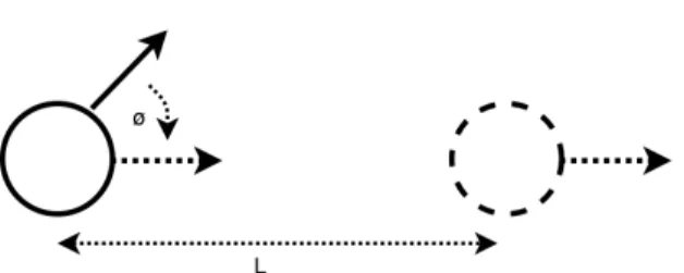
Figure 5.2: The robot first calculates the angle needed to rotate and face the goal φ. It then computes the lengthLneeded to translate.
In Figure 5.2 the robot first calculates the angle needed to rotate the face the goal φ and the computes the length L needed to translate. Equation 5.5 shows the angles calculation and the translation calculation.
x=current_position.x−goal_position.x (5.2) y=current_position.y−goal_position.y (5.3) φ =atan2(x, y)−current_angle (5.4) L=EuclideanDistance(current_position, goal_position) (5.5)
5.2 Physics Based Simulator
To test the algorithm in realistic scenarios, we implemented a physics based simulator. The simulator is built on top of the Bullet physics engine to show realistic simulations. The simu-lator uses the Parasol Motion Planning Library (PMPL) as the motion planning library. PMPL is developed and maintained by the members of Parasol Laboratory at Texas A&M University. See [41, 34, 42] for more information on PMPL.
5.3 Coordinating Hardware and Simulator 5.3.1 Robot-Simulator Communication
We use a server client model to communicate between the simulator and the physical hardware system. The robot runs the Aruco Marker detection program and sends back the calculated camera position when the simulator requests for it. The positions from different markers are averaged together to generate the most accurate approximation of the position.
5.3.2 Inter-Robot Contention Resolution
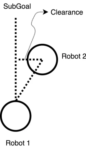
In this section we describe the simple collision avoidance mechanism used to avoid collisions among the agents. Each agent is assigned a priority at the beginning of the program. Workers are assigned a priority that is higher than any helper. Among the workers and helpers, the priority is then randomly assigned. When an agent comes within a certain threshold of any other agent, the lower priority agent halts till the higher priority agent is out of the way. The higher priority agent checks to see if it is going to collide head-on with any of the halted agents. The agent continues if there is no head-on collision. If it is on a head-on collision path, the higher priority agent clears its current path. It then plans a new path using Lazy PRM [43]. All the halted robots are then treated as obstacles. Once the higher priority agent is out of the way, other agents can start moving based on their priorities. Figure 5.3 shows how the robot detects if it is going to collide head-on with another agent. Once the clearance value is less than the robot radius, the agent knows that the current path will lead to a head-on collision.
Lazy PRM waits until the path planning stage to check for collision. Initially nodes are gen-erated and connected using edges assuming that all nodes and edges are valid. Once a path is found from the start to the goal in the given graph, Lazy PRM then checks the edges and nodes for collision. The nodes that are invalid are then removed. A new path is then found or new nodes are added to the graph if needed. In our implementation, instead of deleting the invalid nodes, we mark them as invalid and ignore them in planning. This is done because there could be robots at the invalid nodes. Since we are treating the other robots as obstacles, we want to mark their positions
Figure 5.3: Robot detects if it is going to collide head-on with another agent. Once the clearance value is less than the robot radius, the agent knows that the current path will lead to a head-on collision.
as invalid and mark them as valid once they have moved from there. 5.3.3 Implementation Details
As mentioned before, we use the Player robot interface to control the iRobot Creates. The iRobot Creates receive a command which describes what motor controls should be applied and for how long. The player interface provides aSetSpeedfunction provided by Player library. For the iRobot Creates, the SetSpeed function takes in 3 arguments; forward speed, yaw speed and rotation speed. We ignore the yaw speed. We first make the robot rotate to face the goal, and then translate towards the goal. The control signal is sent to the robot and applied at each time step.
times. The simulator runs at a time resolution of 0.05 seconds, which means each time step for the simulator is 0.05 seconds long. We compute the desired control required to move the robot for the 0.05 seconds at every time step. However, we soon realized that this time was too short for sending the command to the physical robot. We measured the communication time to be around 0.2 to 0.3 seconds over wifi. To accommodate for this we make the simulator plan ahead multiple time steps and execute the commands at once. So in our case, the agent plans for about 6 time steps worth of work and then sends the commands to the physical as well as the simulated robot.
The iRobot Create robots have a very high error rate while moving. In the simulation the robots can move very close to the obstacles and still not hit anything. However, in the physical system that assumption does not hold true most of the time. To solve the issue we sample points that are at least a certain clearance away from any given obstacle. This gives the robots enough buffer to avoid other agents and move safely in the environment.
6. EXPERIMENTS
In this section we present an example scenario where we show how persistently a robot team can perform a task. Here we consider the problem of Zone inspection with robot occupancy limit. 6.1 Setup
In this section we describe the two set of experiments performed. The first set of experiments is a Zone inspection problem where the robots must inspect certain zones assigned to them. The second set of experiments is a patrolling problem where the robots must continuously patrol a given area.
6.1.1 Zone Inspection Problem
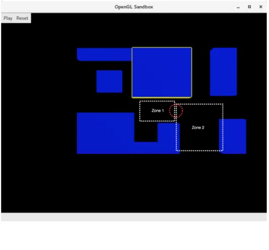
Consider two distinct zones which must be inspected by a robot team of two robots. Each zone must be inspected by a single robot. Each zone has an occupancy limit of one robot at a time. The zones have different sizes which means that one robot will be done with the inspection earlier than the other robot. The smaller zone is designed so that the robot can finish the work and return to a charging location so that it be available to help in the task hand-off scenario. To inspect a zone, a robot needs to visit a set of pre-defined configurations within the zone. A PRM will be used to generate a path between the inspection points. The environment for our testing is room 407 on the fourth floor of Harvey Bum Bright Building. Figure 6.1 shows the simulated model of the building. We also mark the different zones that need to be visited by the robots.
For the Zone inspection experiments, we compare our method against a method that does not allow task hand-off. Following is a brief description of each of the settings. Execution without task hand-off: Each robot inspects its zone on its own. When the first robot completes its task, it will sit idle while the second robot completes its work. If a robot runs low on battery before its task is complete, it will return to a charging station, recharge, and then resume working. Execution with task hand-off: Once the first robot finishes its task, it switches roles to a helper for the second robot.
We vary the traversed size of Zone 2 by increasing the number of goals visited in the zone. This would force the agents to recharge multiple times. We explore the effect of charging rate on the performance as well. We show results from simulated as well as physical robot experiments. 6.1.2 Patrolling Problem
In the second set of experiments we consider the case of robots patrolling a given area. Here we have two workers and two helpers. In this scenario the helpers start off at charging locations while the workers start performing the task. The patrolling zones for the 2 workers is similar to the previous experiment scenario. The agents must repeatedly visit a set of points. Our method allows the agents to swap when the robot is low on battery thereby maintaining the persistency of the task. The environment for our testing is room 407 on the fourth floor of Harvey Bum Bright Building.
Figure 6.1: HRBB 4th floor represented in the Simulator. The different zones are marked with white rectangles. The charging location is marked with a red circle.
6.2 Metrics for Measurement
For the zone inspection problem the metric for measurement is the time taken to visit all the points in different zones by the robots. Total runtime is measured in seconds.
For the patrolling task the success rate was measured by the number of goals reached by the agents.
6.3 Analysis of Results
In this section we will analyze the results obtained from the physical as well as simulated experiments.
Zone 2 = 4 goals Zone 2 = 6 goals Zone 2 = 10 goals Time taken to complete goals (seconds) 0
20 40 60 80 100 120
140 Zone inspection results
Without Hand-Off With Hand-Off
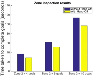
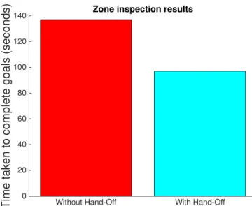
Figure 6.2: Simulator results from the Zone inspection problem. Here we assume that robots can charge instantaneously. We can see that the worker/helper approach does better in all cases than the only worker scenario. As the number of goals in Zone 2 increases, the difference is much more noticeable.
From Figures 6.2 and 6.3 we can see that our method performs better than a scenario where there is no task hand-off allowed. Here we had assumed that the robots can charge instantaneously. In realistic scenarios there will always be some downtime to charging even if the robots could replace their batteries at the charging station. In Figure 6.2 we see the effect of increasing the
Without Hand-Off With Hand-Off
Time taken to complete goals (seconds) 0
20 40 60 80 100 120
140 Zone inspection results
Figure 6.3: Zone inspection problem with finite charging rate. We can see that the worker/helper approach does better in all cases than the only worker scenario. Here we have recharge rate of 20 times the battery discharge rate. Hence the agents have to wait a certain amount before going back to work.
number of goals in zone 2. We can see that as the number of goals increase, the difference between the two approaches increases as well. Increasing the number of goals means that it would take longer time to inspect the zone, hence more battery will be used. This is expected because the worker would need to switch more times in order to recharge its battery. In Figure 6.3 we show results from experiments where the recharge rate is about 20 times the battery discharge rate. Here we can see that there is a bigger difference between the two methods. This is because the task hand-off method allows the helper to recharge while the worker is working. Whereas without the hand-off there is a significant time spent in recharging the robot.
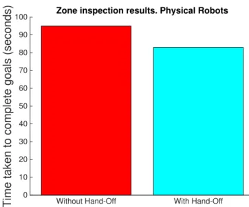
In Figure 6.4 we show the results from physical robot experiments. Here the robot needed to visit 2 goals in Zone 1 and 4 goals in Zone 2. The hand-off method takes about 83 seconds whereas the one without hand-off takes about 95 seconds. The task hand-off method uses Lazy PRM as the contention resolution mechanism. This method added approximately 15s worth of time as the agent needed to replan a route and move around the other agent. This can be improved by using a better contention resolution algorithm.
Without Hand-Off With Hand-Off Time taken to complete goals (seconds) 0
10 20 30 40 50 60 70 80 90
100 Zone inspection results. Physical Robots
Figure 6.4: Physical robot results from the Zone inspection problem. We can see that the worker/helper approach does better in all cases than the only worker scenario. Here we have recharge rate of 20 times the battery discharge rate. Hence the agents have to wait a certain amount before going back to work.
Now we will discuss the patrolling experiments. Our main metric for measurement here is the number of times the agents successfully completed their goals and the number of worker/helper switches made overall. We use four agents in our experiments, two workers and two helpers. Below are the results from ten runs of the algorithm. We define success to be when the workers complete their goals, the helpers successfully switch with workers when needed and then reach charging location. Figure 6.5 shows the results from these experiments.
• Complete Success: This was achieved 30% of the time. Complete Success means that robots were able to complete all the goals and successfully swap with a helper whenever needed.
• Partial Success:This was achieved 20% of the time. Partial success means that some robots completed the goals while others failed. Failure here means that the robot either could not localize or was not able to reach the goals for some reason. It does not mean the robot collided with anything, any collision is treated as a complete failure of the run.
• Complete Failure: The system completely failed 50% of the time. Any robot collision was treated as a complete failure for the fun. Robots have high error rate as discussed above, hence the rate of failure is high.
Complete Success Partial Success Complete Failure Number of times result was achieved0
1 2 3 4 5
6 Robot Patrolling results
Figure 6.5: Physical robot results from the patrolling experiments. We can see that we achieve complete success 30% of the time.
As you can see we get 30% complete successes, 20% partial successes and 50% failures. The failures arise due to a few reasons:
1. The robots have high rate of error, hence they run into each other or obstacles. To fix this we would need a better mechanism to track the error of the robot. An external system dedicated to track the robot’s state would help us in tracking the error. This would allow us to fix the error when we think it is high enough.
2. The robots sometimes over turn or don’t turn enough and end up following wrong path. This is related to the error in movement as discussed in the previous point.
3. Localization can be erroneous at some points and the robot my get "lost". We rely on the robot using its own camera to localize itself. This can be erroneous at times. We need to
track the marker observations the robot has made so far and use that information to remove the outliers when the robot detects new markers.
7. SUMMARY AND CONCLUSIONS
In this work we have presented a way for robots to hand-off their current task to other robots in case they need help and are unable to carry on with the task. We show the task hand-off frame-work in the context of a battery constraint. When a robot is low on battery, it hands off its task before returning to recharge. We show that the tasks get completed faster with task hand-off than compared to methods where task hand-off is not allowed. We show results from a physics based simulator and also physical robot experiments.
We identified several areas of future work. Multi-Robots have multiple other constraints on them such as communication constraint, cargo capacity if they are carrying things around. We would like to study the effect of other constraints through our behavior. Task hand-offs in such scenarios may require further planning. For example shifting cargo from one robot to another.
To improve the physical robot platform, we would also like to develop a better inter-robot contention resolution algorithm. We realize that our inter-robot contention resolution algorithm has some problems which may lead to the robots being in a deadlock in certain cases. We chose this method because it was simple enough and allowed us to demonstrate the capabilities of our algorithm. We would also like to explore better ways of localizing the robot.
REFERENCES
[1] E. Coumans, “Bullet physics engine,”Open Source Software: http://bulletphysics. org, vol. 1, 2010.
[2] “Create 1 programmable robot,”iRobot, http://www.irobot.com/About-iRobot/STEM/Create-2.aspx.
[3] “Eee pc 1015pn | laptops,”ASUS Global, https://www.asus.com/Laptops/Eee_PC_1015PN/. [4] S. Mishra, S. Rodriguez, M. Morales, and N. M. Amato, “Battery constrained coverage,”
2016 IEEE International Conference on Automation Science and Engineering.
[5] B. Kannan, V. Marmol, J. Bourne, and M. B. Dias, “The autonomous recharging prob-lem: Formulation and a market-based solution,” in2013 IEEE International Conference on
Robotics and Automation, pp. 3503–3510, May 2013.
[6] D. Austin, L. Fletcher, and A. Zelinsky, “Mobile robotics in the long term-exploring the fourth dimension,” inIEEE/RSJ International Conference on Intelligent Robots and Systems, 2001. Proceedings. 2001, vol. 2, pp. 613–618 vol.2, 2001.
[7] F. SempÃl’, A. Muôsoz, and A. Drogoul, “Autonomous robots sharing a charging station with no communication: a case study,” inProceedings of the 6th International Symposium on Distributed Autonomous Robotic Systems (DARS), vol. 5, pp. 91–100, 2002.
[8] A. Drenner and N. Papanikolopoulos, “Docking station relocation for maximizing longevity of distributed robotic teams,” inIEEE International Conference on Robotics and Automation,
2006. ICRA 2006. Proceedings 2006, pp. 2436–2441, May 2006.
[9] J. Wawerla and R. Vaughan, “Near-optimal mobile robot recharging with the rate-maximizing forager,” inAdvances in Artificial Life(F. Almeida e Costa, L. Rocha, E. Costa, I. Harvey, and A. Coutinho, eds.), vol. 4648 ofLecture Notes in Computer Science, pp. 776–785, Springer Berlin Heidelberg, 2007.
[10] I. Shnaps and E. Rimon, “On-line coverage of planar environments by a battery powered autonomous mobile robot,” inWorkshop on the Algorithmic foundations of Robotics (WAFR), 2014.
[11] R. Simpson, J. Revell, A. Johansson, and A. Richards, “Multi-cost robotic motion planning under uncertainty,” inIntelligent Robots and Systems (IROS), 2014 IEEE/RSJ, 2014.
[12] A. Kottas, A. Drenner, and N. Papanikolopoulos, “Intelligent power management: Promot-ing power-consciousness in teams of mobile robots,” in IEEE International Conference on Robotics and Automation, 2009. ICRA’09., pp. 1140–1145, IEEE, 2009.
[13] T. Gunn and J. Anderson, “Dynamic heterogeneous team formation for robotic urban search and rescue,”Journal of Computer and System Sciences, vol. 81, no. 3, pp. 553–567, 2015. [14] A. Gage and R. R. Murphy, “Affective recruitment of distributed heterogeneous agents,” in
AAAI, pp. 14–19, 2004.
[15] G. Nagy and J. Anderson, “Active recruitment mechanisms for heterogeneous robot teams in dangerous environments,” in Canadian Conference on Artificial Intelligence, pp. 276–281, Springer, 2016.
[16] C. Pinciroli, R. O’Grady, A. L. Christensen, and M. Dorigo, “Self-organised recruitment in a heteregeneous swarm,” in International Conference on Advanced Robotics, 2009. ICAR 2009., pp. 1–8, IEEE, 2009.
[17] L. Pitonakova, R. Crowder, and S. Bullock, “Understanding the role of recruitment in collec-tive robot foraging,” 2014.
[18] M. J. Krieger, J.-B. Billeter, and L. Keller, “Ant-like task allocation and recruitment in coop-erative robots,”Nature, vol. 406, no. 6799, pp. 992–995, 2000.
[19] L. D. R. d. S. e. S. Junior and N. Nedjah, “Distributed strategy for robots recruitment in swarm-based systems,” International Journal of Bio-Inspired Computation, vol. 8, no. 2, pp. 99–108, 2016.
[20] L. Silva and N. Nedjah, “Wave algorithm for recruitment in swarm robotics,” inInternational Conference on Computational Science and Its Applications, pp. 3–13, Springer, 2015. [21] R. Fujisawa, S. Dobata, K. Sugawara, and F. Matsuno, “Designing pheromone
communica-tion in swarm robotics: Group foraging behavior mediated by chemical substance,”Swarm Intelligence, vol. 8, no. 3, pp. 227–246, 2014.
[22] J. Derenick, N. Michael, and V. Kumar, “Energy-aware coverage control with docking for robot teams,” inIEEE/RSJ International Conference on Intelligent Robots and Systems (IROS), 2011, pp. 3667–3672, Sept 2011.
[23] G. Strimel and M. Veloso, “Coverage planning with finite resources,” inIEEE/RSJ Interna-tional Conference on Intelligent Robots and Systems (IROS 2014), 2014, pp. 2950–2956, Sept 2014.
[24] H. Choset and P. Pignon, “Coverage path planning: The boustrophedon cellular decomposi-tion,” inField and service robotics, pp. 203–209, Springer, 1998.
[25] D. Mitchell, M. Corah, N. Chakraborty, K. Sycara, and N. Michael, “Multi-robot long-term persistent coverage with fuel constrained robots,” in IEEE International Conference on Robotics and Automation (ICRA), 2015, pp. 1093–1099, IEEE, 2015.
[26] Y. Mei, Y.-H. Lu, Y. C. Hu, and C. G. Lee, “Deployment of mobile robots with energy and timing constraints,”IEEE Transactions on Robotics,, vol. 22, no. 3, pp. 507–522, 2006. [27] A. Sipahioglu, G. Kirlik, O. Parlaktuna, and A. Yazici, “Energy constrained multi-robot
sensor-based coverage path planning using capacitated arc routing approach,”Robotics and Autonomous Systems, vol. 58, no. 5, pp. 529–538, 2010.
[28] A. Yazici, G. Kirlik, O. Parlaktuna, and A. Sipahioglu, “A dynamic path planning approach for multirobot sensor-based coverage considering energy constraints,”IEEE Transactions on Cybernetics,, vol. 44, no. 3, pp. 305–314, 2014.
[29] H. Choset and J. Burdick, “Sensor based planning. i. the generalized voronoi graph,” in
Robotics and Automation, 1995. Proceedings., 1995 IEEE International Conference on,
vol. 2, pp. 1649–1655, IEEE, 1995.
[30] F. Aurenhammer, “Voronoi diagramsâ ˘AˇTa survey of a fundamental geometric data structure,”
ACM Computing Surveys (CSUR), vol. 23, no. 3, pp. 345–405, 1991.
[31] A. Kwok and S. Martinez, “Deployment algorithms for a power-constrained mobile sensor network,” inIEEE International Conference on Robotics and Automation, 2008. ICRA 2008., pp. 140–145, IEEE, 2008.
[32] P. H. Borgstrom, A. Singh, B. L. Jordan, G. S. Sukhatme, M. Batalin, W. J. Kaiser, et al., “Energy based path planning for a novel cabled robotic system,” inIEEE/RSJ International
Conference on Intelligent Robots and Systems, 2008. IROS 2008., pp. 1745–1751, IEEE,
2008.
[33] L. E. Kavraki, P. Svestka, J.-C. Latombe, and M. H. Overmars, “Probabilistic roadmaps for path planning in high-dimensional configuration spaces,”IEEE transactions on Robotics and Automation, vol. 12, no. 4, pp. 566–580, 1996.
[34] S. Rodriguez, J. Denny, A. Mahadevan, J. Vu, J. Burgos, T. Zourntos, and N. M. Amato, “Roadmap-based pursuit-evasion in 3d structures,” in24th Intern. Conf. on Computer Ani-mation and Social Agents (CASA), 2011.
[35] S. Rodriguez, J. Denny, T. Zourntos, and N. M. Amato, “Toward simulating realistic pursuit-evasion using a roadmap-based approach,” inMotion in Games, pp. 82–93, Springer, 2010. [36] O. B. Bayazıt, J.-M. Lien, and N. M. Amato, “Swarming behavior using probabilistic
roadmap techniques,” inSwarm Robotics, pp. 112–125, Springer, 2005.
[37] I. Poulakakis, J. A. Smith, and M. Buehler, “Modeling and experiments of untethered quadrupedal running with a bounding gait: The scout ii robot,” The International Journal of Robotics Research, vol. 24, no. 4, pp. 239–256, 2005.
[38] B. Gerkey, R. T. Vaughan, and A. Howard, “The player/stage project: Tools for multi-robot and distributed sensor systems,” inProceedings of the 11th international conference on ad-vanced robotics, vol. 1, pp. 317–323, 2003.
[39] S. Garrido-Jurado, R. Muñoz-Salinas, F. J. Madrid-Cuevas, and M. J. Marín-Jiménez, “Auto-matic generation and detection of highly reliable fiducial markers under occlusion,”Pattern Recognition, vol. 47, no. 6, pp. 2280–2292, 2014.
[40] G. Bradski, “The opencv library.,”Dr. Dobb’s Journal: Software Tools for the Professional Programmer, vol. 25, no. 11, pp. 120–123, 2000.
[41] X. Tang, J.-M. Lien, N. Amato, et al., “An obstacle-based rapidly-exploring random tree,” inIEEE International Conference on Robotics and Automation, 2006. ICRA 2006., pp. 895– 900, IEEE, 2006.
[42] S. Wilmarth, N. M. Amato, P. E. Stiller, et al., “Maprm: A probabilistic roadmap planner with sampling on the medial axis of the free space,” inIEEE International Conference on Robotics and Automation, 1999. Proceedings. 1999, vol. 2, pp. 1024–1031, IEEE, 1999. [43] R. Bohlin and L. E. Kavraki, “Path planning using lazy prm,” inIEEE International
Confer-ence on Robotics and Automation, 2000. Proceedings. ICRA’00., vol. 1, pp. 521–528, IEEE, 2000.