Bulletin of the ACM Slovakia
September
2011
Volume 3, Number
3
Z. P
ř
ik
r
yl
A. Kovárová
P. Sehnalov
á
M.Vaga
č
P. Mederly
M. Kotočová,
M. Bieliková
J. Zendulka,
R. Ružička
Advanced Methods of Microprocessor Simulation
Special Interaction Approaches and
their Impact on
Usability
Stability and
C
onvergence of
N
umerical
C
omputations
A Dynamic Software Evolution by Metamodel Change
Semi-automated Construction of Messaging-Based
Enterprise Application Integration Solutions
Report from Slovak University of Technology
in Bratislava
Report from Brno University of Technology
Published by Slovak University of Technology Press, Bratislava on behalf of the ACM Slovakia Chapter
ISSN 1338-1237 Registration number: MK SR EV 3929/09
1
1
4
26
36
44
55
57
Aim and Scope of the Information Sciences and
Technologies Bulletin of the ACM Slovakia
ACM Slovakia offers a forum for rapid disseminationof research results in the area of computing/informatics and more broadly of information and communication sci-ences and technologies. It is primarily a web based bul-letin publishing results of dissertations submitted at any university in Slovakia or elsewhere, perhaps also results of outstanding master theses. Besides that, conferences that meet bulletin’s expectations with regard to scien-tific rigor are invited to consider publishing their papers in the bulletin in form of special issues. Besides the web version of the bulletin, a paper version is available, too. The Bulletin aims:
• To advance and to increase knowledge and inter-est in the science, design, development, construc-tion, languages, management and applications of modern computing a.k.a. informatics, and more broadly of information and communication sciences and technologies.
• To facilitate a communication between persons hav-ing an interest in information and communication sciences and technologies by providing a forum for rapid dissemination of scholarly articles.
Scope of the Bulletin is:
• original research in an area within the broader fam-ily of information sciences and technologies, with a particular focus on computer science, computer engineering, software engineering and information systems, and also other similarly well established fields such as artificial intelligence or information science.
Types of contributions:
• Extended abstracts of doctoral dissertations.
This is the primary type of article in the Bulletin. It presents main contributions of the dissertation in form of a journal paper together with separate sec-tion with list of published works of the author. In Slovakia and the Czech Republic, it corresponds to typical length of so calledautoreferat. In fact, it is envisaged that publishing the extended abstract in the Bulletin makesautoreferat obsolete and even-tually can replace it completely. It should be noted that by publishing it in the Bulletin, the extended abstract will receive a much wider dissemination. Exceptionally, at the discretion of the Editorial Board, the Bulletin may accept extended abstracts of other than doctoral theses, e.g. Master theses, when research results reported are sufficiently wor-thy of publishing in this forum. Rules and proce-dures of publishing are similar.
• Conference papers. The Bulletin offers
orga-nizers of interesting scientific events in some area within the scope of the Bulletin to consider pub-lishing papers of the Conference in the Bulletin as
its special issue. Any such proposal will be subject of discussion with the Editorial Board which will ultimately decide. From the scientific merit point of view, method of peer reviewing, acceptance ratio etc. are issues that will be raised in the discussion. Besides that the Bulletin may include other types of con-tributions that will contribute to fulfilling its aims, so that it best serves the professional community in the area of information and communication sciences and tech-nologies.
Editorial Board
Editor in ChiefPavol N´avrat
Slovak University of Technology in Bratislava, Slovakia
Associate Editor in Chief
M´aria Bielikov´a
Slovak University of Technology in Bratislava, Slovakia
Members:
Andras Benczur
E¨otv¨os Lor´and University, Budapest, Hungary
Johann Eder
University of Vienna, Austria
Viliam Geffert
P. J. ˇSaf´arik University, Koˇsice, Slovakia
Tom´aˇs Hruˇska
Brno University of Technology, Czech Republic
Mirjana Ivanovi´c
University of Novi Sad, Serbia
Robert Lorencz
Czech Technical University, Prague, Czech Republic
Karol Matiaˇsko
University of ˇZilina, Slovakia
Yannis Manolopoulos
Aristotle University, Thessaloniki, Greece
Tadeusz Morzy
Poznan University of Technology, Poland
Valerie Novitzk´a
Technical University in Koˇsice, Slovakia
Jaroslav Pokorn´y
Charles University in Prague, Czech Republic
Luboˇs Popel´ınsk´y
Masaryk University, Brno, Czech Republic
Branislav Rovan
Comenius University, Bratislava, Slovakia
Jiˇr´ı ˇSafaˇr´ık
University of West Bohemia, Plzeˇn, Czech Republic
Executive Editor:Peter Lacko
Cover Design:Peter Lacko
Zdenˇek Pˇrikryl
∗Faculty of Information Technology Brno University of Technology in Brno Božetˇechova 2, 612 66 Brno, Czech Republic
Abstract
Embedded systems have become indivisible part of our ev-eryday activities. They are dedicated devices performing a particular job. A computing core of more complicated embedded systems is formed by one or more application-specific instruction set processor. Therefore, powerful tools for processors development are necessary. One of the most important phases is the testing and optimization phase of the processor design and target software. In the testing phase, the most often used tool is a simulator. The simulator can discover bugs in the processor design and target software before the embedded system realization. This paper describes several advanced methods of proces-sor simulation, which can be used in the different phases of processor development. In the optimization phase, the most frequently used tool is a profiler. The profiler can uncover problematic parts, such as bottleneck points, in the processor design or in target software. Then, using the results from the profiler, the designer can easily find which parts of the processor design or target software should be modified to get a better performance or reduce the power-consumption. In this paper, two methods of profiling are described. Furthermore, the ways how to simulate and profile multiprocessor systems are also described in this thesis. The processor or multiprocessor system is designed using architecture description language.
Categories and Subject Descriptors
I.6.5 [Simulation And Modeling]: Model Development; I.6.7 [Simulation And Modeling]: Simulation Support Systems
Keywords
Simulation, profiler, hardware/software co-design, appli-cation-specific instruction set processors, architecture de-scription languages, embedded systems
∗Recommended by thesis supervisor: Prof. Tom´aˇs Hruˇska. Defended at Faculty of Information Technology, Brno University of Technology in Brno, Czech Republic on September 9, 2011.
c
⃝Copyright 2011. All rights reserved. Permission to make digital or hard copies of part or all of this work for personal or classroom use is granted without fee provided that copies are not made or distributed for profit or commercial advantage and that copies show this notice on the first page or initial screen of a display along with the full citation. Copyrights for components of this work owned by others than ACM must be honored. Abstracting with credit is permitted. To copy other-wise, to republish, to post on servers, to redistribute to lists, or to use any component of this work in other works requires prior specific per-mission and/or a fee. Perper-missions may be requested from STU Press, Vazovova 5, 811 07 Bratislava, Slovakia.
Pˇrikryl, Z. Advanced Methods of Microprocessor Simulation. Informa-tion Sciences and Technologies Bulletin of the ACM Slovakia, Vol. 3, No. 3 (2011) 1-13
1. Introduction
The area of the hardware/software co-design deals with the design of new embedded systems. These systems are used in devices for the specific application domain, such as network or multimedia processing. They consist, among other things, of one or more application-specific instruc-tion set processors (ASIPs, further referred only as pro-cessors). Each processor usually takes care of specific ac-tions and is highly optimized for it (unlike the general purpose processors, such as x86 family [19]). Hence, the processor has to fulfill several constraints, such as chip size, performance, etc. Furthermore, in the case of mo-bile devices, a designer also has to take care of power-consumption of each processor and the system as a whole. The process of finding the most optimal design according to given constraints can be called either thetrade-off ex-ploration [22] ordesign space exploration (DSE) [26, 31]. The shorter time needed for DSE is always helpful. Be-cause the time needed for the design of processor should be as short as possible, there is a need to have a good in-tegrated desktop environment (IDE) helping the designer in the DSE.
In the IDE, s/he uses tools for the processor program-ming, such as a C compiler or assembler, and tools for the processor simulation, such as different types of simulators or profilers. One of the most important tools used during all processor design phases is asimulator. The simulator is used for testing and validation of the design; it can un-cover hidden bugs. There are several types of simulators. Each type has several advantages and disadvantages and it is used in the different phases of the processor design. The main three types described in this paper are:
• theinterpreted, • compiled, and • translated simulator.
The interpreted simulator is not dependent on a target application (i.e. its creation is based on the processor de-sign only), but it is the slowest type of the simulators. The compiled and the translated simulators in the basic version are dependent on the target application (i.e. their creation is based on the processor design and the target application). The enriched versions of these simulators, which are not dependent on the target application, are also available (so-called just-in-time versions). Note that the translated simulator is the fastest type of the simu-lators. Features of all mentioned types and the concepts used within them are described in this paper. The con-cepts have been designed in a way that the simulators do
2 Pˇrikryl, Z.: Advanced Methods of Microprocessor Simulation
not require a specific platform (e.g. Unix-like systems of
MS Windows) and they are not dependent on any third party platform (e.g. SystemC platform [39]).
When the design hits the optimization phases, the simple simulation is not sufficient. It does not give enough infor-mation about utilization of particular parts of the proces-sor. Hence, the tool calledprofiler is used. The profiler tracks all important activities within the processor dur-ing the target application execution. When the target application ends, the profiler evaluates the collected in-formation and provides an evaluated data to the designer in a readable form (e.g. coverage graphs, such as source code coverage, or lists of instructions or functions which are important for some reason, such as the most executed instructions etc.). The designer can optimize either the processor design itself or the target application. For the processor design optimizations, thelow-level profiler can be used. It uses instructions from the processor instruc-tion set as the main entity to which the statistics are collected to (i.e. it works on an assembly language level). On the other hand, for the target software optimization, the high-level profiler can be used. Then, a function is used as the main entity to which the statistics are col-lected to. Both types of the profilers are also described in this paper.
Nowadays, the embedded systems contain usually more than one processor. In such case, we are talking about the multiprocessor systems on chip (MPSoC) [20]. For instance, a video player can contain:
• one reduced general purpose processor – the control unit, and
• twovery long instruction word processors (VLIW) – the video processing unit, and
• one DSP processor for audio processing.
Therefore, the IDE used for the system design should sup-port the simulation of more than one processor. There are two basic ways described how to simulate these systems. It can be either thesynchronous orasynchronous simu-lation. The first type is used for the simulation of sys-tems with a shared memory. The second type is used for the simulation of the systems without the shared memory, where the processors communicate in other way (e.g. mes-sage based communication). The designer should be able to debug and/or obtain profiling information of such sys-tems. In this case, the profiler tracks utilization of shared resources, such as memories or buses. Both simulation types are described in this paper.
The ADL called ISAC [15, 28] is used for the single-processor or multisingle-processor system description. Note that some of the language aspects are inspired by the LISA lan-guage [14]. The ISAC lanlan-guage has been developed within theLissomproject [24] at Brno University of Technology. 1.1 Goals of the Thesis
There are several main goals. Basically, all of then needs the processor description in the ISAC language. The list of them follows.
• Improve and/or create the new single processor sim-ulation techniques. The speed and accuracy of the
simulation is crucial during the processor design, so the time needed for the simulator creation and the simulation time should be as small as possible. • Add the possibility to debug a running target
appli-cation (i.e. allow different types of the breakpoints, watchpoints setting, etc.).
• Because the system on chip contains also other de-vices, such as I/O dede-vices, the developer should have a possibility to simulate the devices together with the processor core. This technique is called co-simulation.
• Simulation is useful for the testing and validation, but from the optimization point of view, the profiler has to be used. Therefore, one of the main goals is to generate the profiler from the processor description without any additional instrumentation. The pro-filer should provide the information about functional unit utilization and it should also provide informa-tion about instrucinforma-tion set and the target applicainforma-tion utilization.
• Nowadays embedded systems consist of more appli-cation-specific instruction set processors, so the sim-ulation of the multiprocessor systems should be pos-sible. Furthermore, the profiling and debugging of such systems should by also possible.
Note that the author’s contributions fulfill the goals.
2. State of The Art
Nowadays, demands for audio/video applications or net-work applications are very high. For instance, a video de-coder needs to process thousands pixels per single second. Ordinary general purpose processors usually cannot han-dle such a throughput. And even if they could hanhan-dle such the throughput, they are big and they have high power-consumption (e.g. [18, 17]). Therefore, new application-specific instruction set processors are designed. They can preprocess the input stream, so other processor can use the preprocessed stream. Since they are optimized for a particular job, they are smaller, powerful, and consume less energy. This is very important for handheld devices, such as mobile phones or portable game consoles. The technology of the processor manufacturing allows us to place more things on a single chip. By thing, we mean other processors, specialized functional units, or in-put/output devices. This technology also opens a new area for high performance applications. In the applica-tion domains, such as multimedia processing, the input data stream can be divided into several non-conflicting streams. Hence, several processors can work in parallel, which leads to a very good performance of such systems in comparison with the single-processor systems. The methodology of the processor design (i.e. DSE) has significantly changed in the last two decades [33]. The methodology based on an iterative process was very pop-ular at first. In this approach, the processor designers create an informal processor design description. The ar-chitecture is created based on this description. After that, they implement all necessary tools for the processor pro-gramming and simulation, the so-calledtool-chain(i.e. an assembler, simulator etc.). Then, they are able to start the testing of their processor design. This process is very time and money consuming. The designers have to change the design, and then re-implement all the tools based on
Architecture design • HW/SW partitioning • Instruction-set • Microarchitecture Architecture implementation • VHDL/Verilog description • Processor synthesis
Programming and Simulation tools
• Assembler, linker • Disassembler • Simulator • ... Integration • Testing • Validation • Verification
Figure 1: Traditional methodology of a processor design
the results from the testing phase (e.g. a bug was found or the design had poor performance). Furthermore, an ad-ditional testing of the tool-chain itself must be performed to ensure the consistency among the tools. This approach leads tofirst hardware, then software scenario. Such ap-proach is shown in the Figure 1.
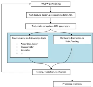
However, it has turned out it is necessary to design both hardware and software at the same time, so the mutual relations between them are explored. The designers can build the architecture accordingly to the algorithm it ex-ecutes. Without concurrent design of the hardware and software, it is difficult to explore various trade-offs like whether a task should be handled by hardware or by soft-ware, and also to adjust the hardware/software interface. The more effective way of the design space exploration is the use of architecture description languages (ADLs). They allow the hardware/software co-design. The de-signer describes the processor in the selected ADL and the complete tool-chain is automatically generated. The hardware description can also be generated from the same processor description. The software developers can start to write the target application, and meanwhile, the hard-ware designers can work on the processor microarchitec-ture and/or other functional units, which do not influ-ences/conflicts with the software development (e.g. a modification the processor instruction set). This leads to shorter design phases, so the final design is created in a fraction of the original time. Furthermore, the au-tomatically generated tools are usually based on formal models which often imply better chances for the proces-sor design verification/validation. The way of the hard-ware/software co-design is shown in the Figure 2. There are a few projects which try to give the developers a whole IDE for the processor design. Each of them uses its own description language which has been developed within the project. Some of the important projects are mentioned in this section.
An open source project ArchC [1] uses the eponymous ADL [2]. It is a description language for pipeline sys-tems. It is based on SystemC platform. The processor description is composed of several parts. The designer can describe the resources, such as memories or registers, the instruction set and its behavior. S/he can also
de-Architecture design, processor model in ADL
Tool-chain generators, HDL generators
Programming and simulation tools • Assembler, linker • Disassembler • Simulator • ... Hardware description in VHDL/Verilog Processor synthesis Testing, validation, verification
HW/SW partitioning
Figure 2: Processor design methodology using the ADL
scribe the processor microarchitecture. The behavior is described with C constructions and SystemC functions from the delivered shared libraries.
Another widely used ADL is LISA [14]. The processor description in the LISA language is composed of several parts. In one part, the resources are defined. In the other part, the instruction set with the behavior and processor microarchitecture is described. The behavior of instruc-tions is described using the C language.
TheSim-nML[37] project uses an ADL callednML[7]. This ADL can be used only for simple models without pipelines and other timing features. In its basic form, it is suitable for instruction set modeling only. Note that there are some extensions [8] adding a support of microar-chitecture description.
At the Vienna University of Technology, an ADL called
xADL[3] has been developed. The processor is described as hardware blocks which are interconnected. Since one uses the hardware blocks, the model is at cycle-accurate level. A part of the tool-chain generation is based on the
LLVM platform [25].
The comparison of simulators which are available in the other projects follows. Although from all mentioned lan-guages the interpreted simulator can be generated [2, 4, 7, 14], as far as the author knows, the simulators use the dynamic scheduling of events, which decrease the simu-lator performance. Our proposed solution replaces the dynamic scheduling with the improved static scheduling (the differences are described in the following section). The compiled simulator can be also generated from all mentioned languages. Note that the simulation platform in the ArchC project uses the SystemC platform. The interpreted simulator is dependent on the SystemC plat-form, but the final binary of compiled simulator is not [1]. The generated code can be compiled by a normal com-piler. The compiled simulator does not have the just-in-time features and the self-modifying code is not
sup-4 Pˇrikryl, Z.: Advanced Methods of Microprocessor Simulation
ported (support for self-modifying code has to enabled even for the interpreted simulator). From the description in the LISA language the compiled simulator can be also generated. It is based on a table containing sets of func-tions [31]. In each clock cycle, a particular set of funcfunc-tions is executed (e.g. a set can contain functions for fetch and decode pipeline stage). They also provide a just-in-time compiled simulator [31], so the self-modifying code is sup-ported. The compiled simulator can be generated from the nML language in the Sim-nML project as well, but is does not support self-modifying code and it also does not have the just-in-time features [11].
All types of simulators can be generated from the proces-sor model in the xADL language. The simulator is de-pendent on the LLVM framework, so the time needed for its creation can be quite high (compilation of the LLVM platform takes a lot of a computation time) [3].
The basic profiler can be generated from the processor description in the ArchC project. It collects statistics by the tracking of executed instructions within the proces-sor microarchitecture [1]. The Sim-nML project provides the basic profiler generated from the instruction-accurate model. A profiling statistic can be achieved by the in-jection of new code into an application [37]. In both projects, the profilers are integrated to an interpreted or compiled simulator and, as far as the author knows, the profilers are low-level (i.e. statistic, such as how many times a particular instruction was executed, are avail-able). Their profilers can be compared with the proposed low-level profiler. A high-level profiler for the C language is not available at those projects till this time. Within the project running at the Vienna University of Technology, no profilers are available [3]. The LISA allows a descrip-tion of pipeline models and the profiler at an assembly language as well as a profiler for the C language can be also generated [14]. Unfortunately, none of the mentioned project provides any information about types of statistics or speeds of theirs profilers, so the comparison with the proposed profilers cannot be done.
3. Description Languages
The description languages used for the processor descrip-tion can be divided into two basic classes. The first one contains the hardware description languages (HDLs), such as VHDL [42] or Verilog [41]. Although these languages have capabilities of the processor description, the level of abstraction is very low. In other words, these languages demand deep details about the new processor architec-ture. This is not very suitable for the rapid processor prototyping or for the fast DSE. These details can be unimportant or unknown at the beginning of the processor design (in early stages of the design space exploration) or they can change a lot within the processor design phases. Therefore, their specification costs a lot of a developer time. This is one of the reasons why the second class has appeared.
The second class contains the architecture description lan-guages (ADLs). They use a higher level of abstraction, so they allow the fast changes of processor microarchi-tecture or an instruction set description. They are more suitable for the fast processor or multiprocessor system prototyping. The details needed by the HDLs are either computed automatically or the ADLs contain construc-tions for them with a higher level of abstraction. The
main class of ADLs can be divided into three sub-classes. The description of each sub-class follows.
• ADLs focused on the instruction set description. These ADLs are focused only on the processor in-struction set description. The processor microarchi-tecture is not described at all. The advantage of these languages is that the tools for the processor programming are easily generated based on the de-scription. The hardware description cannot be gen-erated since there is no description of the proces-sor microarchitecture. Hence, such languages can be used if we need the tools for the target software development. One of such languages is nML [7]. • ADLs focused on the processor architecture
descrip-tion. The processor description consists of inter-connected blocks. Each block represents some func-tional unit in the processor (e.g. an adder, a fetch unit). The advantage is the description can be eas-ily transformed to some HDL (ports of functional units are known so are the interconnections among them). The problem is with the instruction set ex-traction (the textual form of instructions etc.). It is not explicitly described anywhere, so the tools for processor programming are not obtained fully auto-matically. One of these languages is MIMOLA [27]. • Mixed ADLs. These languages combine the advan-tages of previous two sub-classes. The processor de-scription consists of the instruction set dede-scription and the processor microarchitecture description. It should be noted that the microarchitecture descrip-tion is opdescrip-tional. If the processor descripdescrip-tion con-tains the microarchitecture, then the programming tools and the hardware description are generated from the same processor model. The ArchC [2], EX-PRESSION [10], LISA [14], RADL [38], xADL [3] or ISAC [15] languages are examples of mixed ADLs.
The last mentioned ADL ISAC is used as the ADL in this paper. The programming and simulation tools are generated based on the processor description in this lan-guage. The hardware description can be also generated. The next subsection contains detailed description of this language.
3.1 The ISAC Language
The ISAC language was developed within the Lissom [24] project at Brno University of Technology. It is inspired by the LISA language, but it extends LISA with additional constructions allowing the faster processor or multipro-cessor system prototyping. The promultipro-cessor model itself consists of two basic parts. In the first one, the processor resources, such as registers or memories, are described. In the second one, the processor instruction set and the pro-cessor microarchitecture are described. The second part forms the four basic models of the processor. Each model describes different features of the processor.
There are
• theinstruction set model, • thebehavioral model, • thetiming model, and
ISAC Language Processor resources group constructions
operation constructions Instruction set model Behavioral model Timing model
Hierarchy of instruction decoders
Figure 3: Structure of the ISAC language
The basic construction which is used in these models is theoperationconstruction. The operation can have sev-eral sections. Each section is used for a description of some model. Theassemblerandcoding sections are used for the instruction set model. They describe the textual or binary form of an instruction (or its part). The ex-pression or behavior sections are used for the behavior model. The subset of the ANSI C is used in these sec-tions. These sections can also be used for the descrip-tion of behavior of the funcdescrip-tional units in the processor microarchitecture (operations without the assembler and coding sections; such operations are calledevents). Note that the expression section has the same meaning as the return statement in a C function (i.e. it is used for return-ing of a value if a particular operation is used durreturn-ing an instruction decoding). Theactivation section is used for the timing model description. It denotes what and when will be done during the target application execution, such as pipeline stalls etc. Thestructure section is used for the model of hierarchy of instruction decoders. It describes when and which decoder will be activated during the tar-get application execution (e.g. the pre-decode and decode phase of an instruction execution in a pipeline).
The operations can be grouped according to some similar-ities. For instance, the developer can group operations de-scribing the arithmetic instructions. For such situations, s/he can use thegroupconstruction. All grouped opera-tions can be accessed via the created group later in the model. Note that the groups can be also put together. The operation can be also connected to another opera-tion or group (i.e. the operaopera-tion can use other operaopera-tion or group). For such connection, theinstance statement is used at the beginning of the operation construction. Typically, an instruction is formed by several connected operations and/or groups. The processor model contains many operations and groups. The structure of the ISAC language is depicted in the Figure 3. There are three special operations (events) which have to be described in each processor model. The eventmain is a special event which is executed at the beginning of each clock cycle (i.e. it is used for the clock cycle generation). It is also called
synchronization event. The eventreset is performed be-fore the simulation starts and brings the processor into the defined state. And then, there needs to be the event
halt, executed when the simulation ends.
The model can be written in two levels of accuracy – the instruction-accurate or cycle-accurate level. In the
case of the cycle-accurate level, all four models have to be described, whereas only the instruction set model and the behavior model has to be described in the case of instruction-accurate level. The detailed description of the ISAC language constructions used in this thesis follows.
4. Formal models
The tools for the processor programming and simulation can be created in several ways. One can take the pro-cessor description and each operation or group transform into one or more functions. Although this approach is straightforward, it does not have many good properties (especially if we want to validate/verify the generators). Therefore in our case, the generators of these tools are based on the formal models. The fact that the processor description is captured in the formal models brings several advantages. Among the others, there is only one represen-tation of particular processor features. Therefore, an op-timization can be performed on the single model and the optimization will be reflected in all generated tools for the simulation or programming. The simulator and the hard-ware realization are generated also from the same formal models, only the generator language back-end differs (C or VHDL code generator). Therefore, no additional huge validation of a generated hardware description is needed. The different forms of a finite automaton have been cho-sen as the basic formal model. The reason for that is that the finite automaton is easy to implement either in the C language or in some HDL (VHDL or Verilog). Addi-tionally, the assembly and machine languages are finite (and regular) languages, so it is appropriate to use the finite automaton without cycles as an acceptor of those languages.
There are four formal models which captures different as-pects of the described processor. The processor instruc-tion set is captured in so-called two-way coupled finite automata [16]. Based on this model, tools, such as an assembler, disassembler, are created. The simulator par-tially uses this model. The processor microarchitecture is captured in the so-calledevent automata. The event au-tomata represent the controllers in the processor microar-chitecture. The algorithm creating the event automata is based on the activation tree. The activation tree cap-tures the relationships among the events in the processor microarchitecture (i.e. it knows which events should be activated in a particular clock cycle). It is also used for profiling purposes too. The last model is the decoding tree. It is used in the profiler for the computation of the instruction set coverage.
5. Single-processor Simulation
Simulation is one of the most important (and in some cases the only one) ways of a testing and validating the processor design. Therefore, it is significant to have a good simulation platform with several types of simulators. The three types of simulators are presented in this section. Each type has its advantages and disadvantages. 5.1 Generated Simulators
The first type is aninterpreted simulator. The concept of this simulator is based on a constant fetching, decoding and execution of instructions from memory element. The disadvantage of this concept is that instructions within a loop in the target application are fetched and decoded sev-eral times, although they have not been changed. There-fore, the simulation itself is relatively slow. On the other
6 Pˇrikryl, Z.: Advanced Methods of Microprocessor Simulation
hand, the simulator itself is not dependent on the target application (i.e. the simulator can simulate any target application), and furthermore, the self-modifying code is supported out of the box (i.e. it is supported by the de-sign). The time of the creation of the interpreted simula-tor is also relatively short (the shortest of the all types of the presented simulators).
The simulator generated from the processor description in the ISAC language is formed from three basic parts. The first part simulates the processor resource. Each resource has to be transformed into a C construction. Each con-struction should be as optimal as possible from the host computer point of view, so specific inline functions and/or macros are used. The second part simulates the instruc-tion decoders. It is based on the two-way coupled finite automaton. The automata are transformed into the C construction according to the algorithm described in [34]. The third part is the part that simulates the processor microarchitecture. The algorithm transforming the event automata to the C language construction is described in [28]. The event automata form the static scheduling of events within the microarchitecture. The concept of the interpreted simulator works for both levels of accu-racy in the same way (i.e. the concept of the simulation creation is independent on the level of accuracy of the processor description).
If the developer wants to increase the speed of the simula-tion, s/he can use the second type of simulator, the com-piled simulator. It is created in two steps. In the first step, the target application is analyzed. The C code simulat-ing the target application is emitted ussimulat-ing the information from the analysis. In the second step, the emitted C code is compiled together with the static C code of the sim-ulator, such as processor resources etc. The compilation time of the emitted code should be as small as possible, so the emitted code has to be structured into a specific form. If the emitted code is placed in functions, the functions cannot be arbitrarily big because it can lead to serious compilation problems, such as not enough virtual mem-ory or bad (long) optimization process. Therefore, the address space of the target application is divided into sev-eral non-overlappingfragments. The emitted code for a particular fragment is compiled independently. It is clear that this version of the compiled simulator (also known as astatic compiled simulator) is dependent on the target application and the self-modifying code is not supported. Nevertheless, the speed of such simulator can be several times faster than the speed of the interpreted simulator. The second version of the compiled simulator is the just-in-time compiled simulator (JIT). It supports the self-modifying code and it is not dependent on the simulated application. It is created in only one step and it works in the following way. At the beginning of the simulation, the simulator works as the interpreted simulator. The main task of this phase is to find the so-calledhot-spots (i.e. parts of the target application in which the most of a sim-ulation time is spent in, e.g. function). Then, these parts are compiled only, so the subsequent simulation of these parts will be quite faster. In our case, the smallest size of the hot-spot is not a function, but the fragment. Each host-spot analysis create new file with C code. The cre-ated file is compiled as a dynamic library. It is supported by the all major platforms (e.g. dll files in the MS Win-dows,sofiles in the Unix-like systems, etc.). Furthermore,
this type of libraries can be loaded by the running pro-gram. Dynamic library loading is also supported by the all major platforms (e.g. functionLoadLibrary in the MS Windows, functiondlopenin the Unix-like systems, etc.). When the fragment is compiled as the dynamic library, it is then loaded by the running simulator. Next time the simulator hits this fragment, the new function from the created library is executed instead of the using slow in-terpreted simulation. Thanks to the first part (hot-spots location), the speed of the just-in-time compiled simulator is slower than the speed of the static compiled simulator. Still, it can be several times faster than the speed of the interpreted simulator. The compiled simulator creation can take more time than the creation of the interpreted simulator (especially the just-in-time compiler simulator). The last type of simulators mentioned in this paper is the
translated simulator. It improves the compiled simulator. The translated simulator is the fastest type of simulators, but it needs some additional information about the tar-get application. It needs starting and ending addresses of all basic-blocks in the target application. Thanks to this information, the simulator can be highly optimized. The addresses are stored usually as debug information in the target application. These addresses cannot be obtained via a static analysis of the target application, because of indirect jump instructions. Such instruction uses a value of a register or memory as a destination address of the jump. Therefore, the static analysis does not know where the instruction will jump in a runtime. The only way how to reliably obtain the addresses is to use a high-level lan-guage compiler. If it is used for the target application cre-ation, then it knows exactly where the basic-blocks start and end, and it can simply store the addresses in the tar-get application as the debug information. It should be noted that we also provide the C compiler generation. The C compiler is created from the same processor model as the simulation tools or programming tools (see author’s publications). The translated simulation has also two types, the static translated simulation and just-in-time translated simulation. It uses almost the same concepts as the compiled simulation (i.e. the address space is also divided into the fragments and the basic idea of the JIT translated simulator is the same as in the JIT compiled simulator).
The interpreted and compiled simulators can have two levels of accuracy. They can be either the instruction-accurate one or the cycle-accurate one. The translated simulation can be created only at the instruction-accurate level now because of the performance reasons. Note that the translated simulation at the cycle-accurate level is un-der research.
An additional property of the interpreted simulation is theevent processing(i.e. how the simulator activates and executes behavior of the events in the processor microar-chitecture). The processing of the events can be done via dynamic scheduling of events [14]. It is based on a principle of an event calendar [35]. The event calendar determines which events have to be executed in a partic-ular clock cycle. According to the executed events, new events are dynamically activated (planned for the execu-tion), which means they are added into the event calendar. This analysis is done in the runtime of the simulator, so it quite decreases the simulator performance. On the other hand, the processing of events can be done via a static
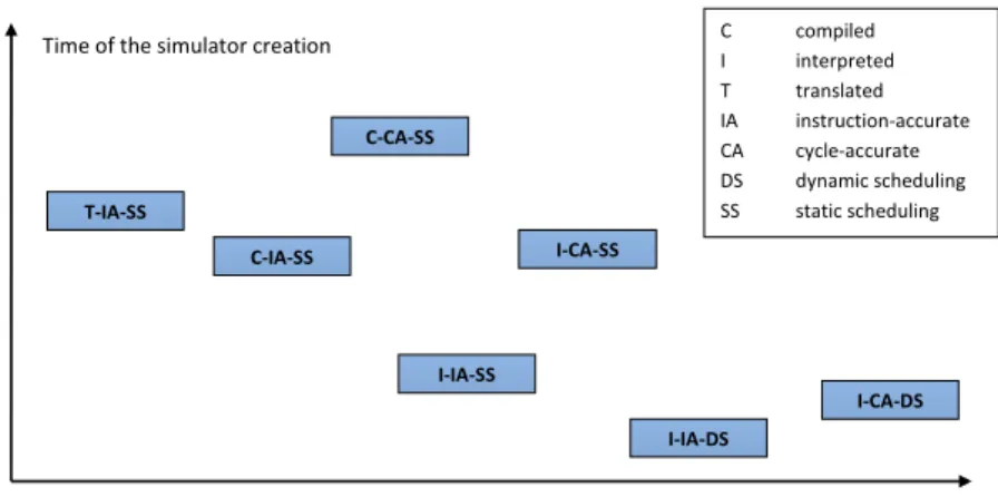
scheduling of events [14]. First, the processor microar-chitecture is analyzed and sets of events, which have to be executed in a particular clock cycle, are determined. Second, a set of functions, which represents the events, is assigned to a particular clock cycle. Note that with more complicated timing models, combinations of the event ac-tivations raise rapidly, so with the static scheduling, a size of the simulator increases. However, the actual simulation is very fast. The compiled and the translated simulation always use the static scheduling of events in our case. Figure 4 depicts the simulation speed with regards to the time, which is needed for the simulator creation.
All simulators with the static scheduling are available in the Lissom project. The experimental results and the comparison with other projects are shown at the end of the paper. The text in this section is based on the author’s publications.
5.2 Debugger
The debugger is a tool that helps the developer search and remove the processor or target application bugs1(the
de-bugging can be seen as a process of bug removing [36]). There are several possibilities to the target application de-bugging, such as program instrumentation, post mortem analysis, or other methods [12]. The developer can also use simple printouts inserted in the processor descrip-tion for debugging purposes. But sometimes, especially in complex processor descriptions and/or complex target applications, it is not enough. Therefore, all types of the simulators include a debugger (except the translated sim-ulators; although it is possible, the debugger is omitted for performance reasons). In general, the debugger can have several features. The most important feature, which all debuggers should have, is that the debugger must not influence the original semantic of the target application in any way [9]. The text in this section is based on author’s publication.
The developer can debug the target software before the real processor is available in the Lissom project at three levels of abstraction:
• cycle-accurate level,
• instruction-accurate level, and • source (statement) level.
The lowest level of the abstraction is the cycle-accurate level. It uses single clock cycle as basic step in the debug mode. The developer can see what is happening during an instruction execution in processor microarchitecture (e.g. an instruction passage through the processor pipeline). The disadvantage of it is that the instruction is not ex-ecuted at once, so the semantics of the instruction will change the processor state in the future clock cycle. The developer has to be aware of this behavior. Note that it is also very hard to debug target program at this level, but it can be very useful in the case of optimizations of the target program or for the processor microarchitecture debugging (e.g. debugging of the processor pipeline).
1bug is a defect in a target program or in a processor
model
The second level has a single instruction as the basic step in the debug mode. Each instruction is executed at once, even if it takes more clock cycles. This level is useful for debugging at assembly language level. It should be noted that the previous levels does not need any additional in-formation about the target application, such as symbol names, etc.
These kinds of debuggers allow runtime control via set-ting the conditional or unconditional breakpoints, step-ping, resuming, or setting the conditional or uncondi-tional watchpoints. They also support an evaluation of processor resources, such as obtaining the actual value of any processor resources (note that the expressions are also supported). More, the processor resources can be set to a given value, or memory dumps can be performed, etc. The debugger itself is a part of the simulator.
The crucial feature of any kind of the debugger is the optimal breakpoint detection. The following concept is used in the Lissom project. The address of each decoded instruction is checked by the debugger during the instruc-tion decoding. If the address matches one of the break-point addresses, the execution of the target program is stopped and the developer can investigate the state of the target program or processor microarchitecture. The address of decoded instructions is stored in the resource specified in the processor description. This solution is similar to hardware breakpoints, except the breakpoint address is not stored in the processor register but within the debugger itself.
The last level uses the whole statement of a higher pro-grammable language as a basic step in a debug mode. This level is dependent on debug information generated by a higher programmable language compiler. Note that this level is out of the scope of this paper, so it is not described here, but additional information can be found in [23].
The developer should have a possibility to debug the tar-get program on the real hardware. This refers to the
on-chip debugging. It is very useful either for the testing of the hardware or for the debugging of the target appli-cation on real hardware (the speed of the real processor is usually higher than the speed of the simulator). The col-lection of different levels of debugging can be called multi-level debugging (the developer should be able to switch among the abstraction levels as s/he wants).
5.3 Co-simulation
The embedded systems contain additional devices on a chip. It can be some I/O devices or other functional units, which do not belong to the processor core, such as DRAM controllers etc. These functional units can be modeled at a different level of abstraction using different languages. Therefore, we must add a support forco-simulationof the processor core described in the ISAC language and these functional units. We distinguish between two versions of co-simulation. Either the simulator can be used by other simulation platform, such as ModelSim, or the simulator can simulate additional functional units using so-called
plugins.
In the first approach, the simulator is used by a different tool. There are many APIs created by different vendors, such asDPI [40],FLI [32], etc. The simulator has to be
8 Pˇrikryl, Z.: Advanced Methods of Microprocessor Simulation
Simulation time Time of the simulator creation C compiled
I interpreted T translated IA instruction-accurate CA cycle-accurate DS dynamic scheduling SS static scheduling C-IA-SS I-IA-SS I-CA-SS C-CA-SS I-IA-DS I-CA-DS T-IA-SS
Figure 4: The simulation speed comparison
enriched by some functionality based on the mandatory part of the vendor API.
In the second approach, the functional units are modeled in any language that can build dynamic libraries (e.g. C++, . . . ). The dynamic library can be called plugin
in this context. The dynamic library can be linked to the simulator (or it can be loaded by the running simu-lator). This allows the complex system simulation. For instance, the developer can design timers/counters in the C language. S/he can also design an LCD display and a keyboard. If s/he starts the simulation, the all functional units together with the processor core are simulated in parallel. The plugins can be reused in a different pro-cessor description with the same interface, which is very good feature.
Since both types of the co-simulations are supported, the developer can combine both concepts, so the created sim-ulation platform is very powerful.
6. Single-processor Profiling
One of the key roles concerning the application-specific instruction set processors development cycle is the opti-mization of it and an optiopti-mization of target programs. From the optimization point of view, simple simulation is not enough way since it does not provide enough of nec-essary information, such as detailed statistics about the processor resources or the target program utilization. For this purpose aprofileris used. The profiler tracks all the important activities in the processor microarchitecture, so that detailed statistics about them can be gathered. Af-ter the profiler ends, the designer gets some information, such as lists of instructions which are important from the different points of views (e.g. the top five of the most frequently used instructions or the top five of the most frequently memory-active instructions). The profiler also gives some information about the target program (e.g. the list of functions in which the most of execution time was spent in, or the list of the most frequently executed func-tions). From this information the developer can identify the functional units, which are overloaded; or units, which can be safely removed or replaced with more proper units. S/he can also easily improve the target program perfor-mance because the most problematic functions (or parts of them) are detected, and therefore can be rewritten. The profiler has several characteristics which determine
its behavior and accuracy of its output statistics (e.g. the profiler can work at an assembly language level or in a more abstract level, for example, at the C language level). We can distinguish between high andlow level profilers. The low-level profiler has as a basic entity of interest a single instruction from the processor instruction set. In such case, the profiler does not need any additional in-formation about the target application (an instruction is denoted by its operation code and this is taken from the processor description). The high-level profiler’s basic en-tity of interest is usually a function (or other constructions from a higher programmable language
The architecture dependent low and high-level profiler can be generated using information about the processor instruction set and microarchitecture from the processor description. The text in this section is based on the au-thor’s publications.
6.1 Generated Profilers
The profiler is built in two phases and it uses the same formal models as the simulators. Since the microarchitec-ture is capmicroarchitec-tured in the event automata, the architecmicroarchitec-ture dependent profiling functionality, such as an instruction tracking, is inserted in into the event automata. The architecture independent profiling functionality, such as evaluation of the most executed instructions, is stored outside of the event automata, so that functionality does not slow down the profiling. The key thing of the profiling functionality is the detection of the beginning and end of an instruction (correct cycle-accurate statistics). The in-struction tracking is based on theenriched queues which are generated using the activation tree.
During the profiling the objects used for storing infor-mation about instructions are filled. When the profiler ends, these objects are analyzed and several statistics are created. The following statistics are created:
• a list of the five most executed instructions, • a list of five instructions taking the most execution
time,
• a list of the five most memory active instructions, • an instruction set coverage, and
When the target application is written using C language, the developer wants to see the statistics related to the C application. In such case, the profiler for C language is used. It is also fully generated from the processor descrip-tion. This compiler stores all needed information such as a table with functions together with addresses denoting where the functions begin and end. The table is stored in the target application as debug information. The profiler uses this information for the function identification dur-ing the target application run. The core of the profiler is quite the same as the core of the profiler for the assem-bly language. The key thing of the profiling functionality is also the detection of the beginning and ending of an instruction (correct clock cycle statistic). The instruc-tion denotes the funcinstruc-tion which is actually executed. The profiler at C language level uses the same algorithm as the profiler at an assembly language level. The collected statistics are quite similar to the statistic in the low-level profiler, but this time, the function is the main object of interest. The following statistics are created:
• a list of the five most executed functions, • a list of the five most memory active functions, • a list of the five functions taking the most execution
time,
• a list of all executed functions, • a source code coverage, and • a call-graph.
7. Description, Simulation and Profiling of
MP-SoC
Nowadays embedded systems, especially for multimedia processing or network applications, consist of more appli-cation-specific instruction set processors, therefore the de-veloper should have a possibility to describe such a system using one ADL. Based on used processors, the MPSoC can behomogeneousorheterogeneous. The homogeneous MP-SoC is formed from the same type of processors. If there is only one global shared memory among the processors (they communicate via this memory), then the system is often called amulti-core processor. If each processor has its own memory and the communication is done via mes-sages (they are sent over the network on chip [13]), then the system is callednetwork on chip. On the other hand, a heterogeneous MPSoC uses a reduced general purpose processor as a control processor and some DSP/VLIW processor(s) for an audio/video processing. In the follow-ing text, the term multi-core processor denotes homoge-nous MPSoC with shared memory and the term MPSoC denotes heterogeneous MPSoC.
In complex systems, such as multi-core processors or MP-SoCs, interconnections among cores or processors, as well as connection to shared memories, etc., have to be de-scribed. The interconnection should be described using the ADL as well. However, the support for description of such things is very weak or completely missing nowadays ADLs (e.g. nML, LISA, etc.). Therefore, new construc-tions in the ISAC language have been added.
Each processor used within the multiprocessor system is described in a separate processor description; therefore the whole tool chain and simulation tools are created for it. The processor can communicate with other processor cores via shared resources or via other medium, which is
Presentation Layer
Middle Layer
Simulator Simulator
Simulation Layer Simulator
Figure 5: Three-layer architecture
simulated using the co-simulation techniques. Therefore, the ISAC language constructions describing memory ele-ments, such ascache or ram construction, and construc-tion describingbuses can be shared. Each of the shared resources is owned by a single core/processor. This re-source is marked as shared in the processor resource scription so they can be accessed in other processor de-scription. Note that in the case of cache description a cache coherence protocol is specified.
In the following text, the concept of the multi-core pro-cessor and MPSoC simulation is described. It should be noted that some of the principles that are described fur-ther, such as a copying of a simulator to a network host, are also used in a single-processor simulation.
The single-processor and MPSoC simulation platform in the Lissom project is based on the so-called three-layer
architecture. They are thepresentation,middle,and sim-ulation layer (see Figure 5). The layers uses message based protocol, where the messages are sent using a stan-dard TCP/IP protocol [5]. The presentation layer accepts commands from the developer, such as a start of a simula-tion, and displays important informasimula-tion, such as results from the simulation. The presentation layer can have sev-eral forms. There is a graphic user interface (GUI) in a form of a plugin forEclipseplatform [6]. Advanced users can use a command line interface (CLI) allowing scripting and other advanced techniques, such as automatic test-ing, etc. The presentation layer communicates with the middle layer. The middle layer accepts commands and processes them. For example, it accepts a command that the developer wants to create a simulator from a proces-sor description, so the middle layer creates a simulator and sends message to the presentation layer about any possible errors that have occurred.
The middle layer also takes care of an installation of the simulator into the simulator layer. The simulators can be installed into any suitable host in a network, according to the user configuration. After the simulator is installed, it is executed and waits until it receives a message which starts the simulation. This message is sent by the middle layer based on user’s command (i.e. user action from GUI or a command entered in the command line).
The first simulator in the configuration file is the so-called boss-simulator. We provide two kinds of simula-tion. There is synchronous and asynchronous MPSoC simulation. In the asynchronous simulations, the boss-simulator is just an ordinary boss-simulator without any spe-cific tasks. The simulators are synchronized within the target application (i.e. the target application is
responsi-10 Pˇrikryl, Z.: Advanced Methods of Microprocessor Simulation
ble for valid reading and writing to the shared resources). This kind of simulation is suitable for example for NoC ar-chitecture simulation (generally, the systems where there is no shared memory among the processors). On the other hand, the synchronous simulation is designed for the sys-tems with shared memory. In the case of synchronous simulations, the boss-simulator is used for the clock cycle generation
The developer can set breakpoints on any source code line in any target application. Hence, any processor of MPSoC can hit one of the set breakpoints. If some of the simulator within MPSoC hits the breakpoint, it stops and all other simulators also stop (note that this behavior can be changed in the case of the asynchronous simula-tion). Then the developer can obtain/set a value of/to any resource of any processor etc. Also, s/he can con-trol application execution flow in step mode. In the case of synchronous simulation, the step is performed by all simulators. In the case of asynchronous simulation, the step can be performed either by all simulators or by a particular simulator only. The simulator can also be re-sumed from stepping mode. Resuming works in similar way as the step mode, so either all simulators are resumed or, in the case of asynchronous simulation, only selected simulators can be resumed.
The profiling information about the shared resources can be obtained when the profiling of the target applications ends. Each target application can be profiled by one of the presented profilers. Furthermore, the profilers are en-riched about a shared resources tracking. It means that the profiler created from the processor description own-ing some shared resource tracks, among the other thown-ings, accesses to the shared resource. At the end it can give statistics displaying how many times has the resource been accessed by a particular processor. By this way, the designer can find the bottle-neck points among the processors sharing that resource.
The text in this section is based on the author’s publica-tions.
8. Experimental Results
In this section, the results of the solution using the ISAC language are provided. Several programs from
MiBench [29] test suite (e.g. crc32, sha, dijkstra, etc.) were chosen as the testing algorithms. The results shown in the graphs are the average values from several runs (the maximum and minimum values differ from the av-erage values in tenths of a percent). All simulators were compiled with the gcc (v4.4.5) compiler with optimiza-tions–O3 enabled. The tests were performed on the In-tel Core2Quad with 2.8 GHz, 1333 MHz FSB and 4GB RAM running 64-bitLinux based operating system. The speed is measured in themillion instructions per second
(MIPS).
The first comparison is the comparison with the ArchC project (see Figure 6). They provide interpreted and compiled simulator. The comparison is done using the MIPS architecture [30]. Unfortunately, the speed of the bit count and dijkstra are missing (they are not available on the project web pages). As one can see, the interpreted simulator is a little faster in average than the interpreted simulator based on the ArchC language. The compiled simulator beats their compiled simulator a lot. It is more than two times faster in several cases.
0 10 20 30 40 50 60 70
bit count crc32 dijkstra quicksort sha
M
IP
S
Interpreted simulator, ArchC Intepreted simulator, Lissom Compiled simulator, ArchC Compiled simulator, Lissom
Figure 6: Speeds comparison with the ArchC
project
1 10 100 1000
bit count crc32 dijkstra sha stringsearch
M
H
z
Interpreted simulator, xADL Interpreted simulator, Lissom Translated simulator, xADL Translated simulator, Lissom
Figure 7: Speeds comparison with the xADL
project
The next project is the project running at Vienna Univer-sity of Technology using the xADL language. The com-parison is based on their publication [4]. Five algorithms from the MiBench test suite are compared. The compar-ison is done using the MIPS architecture too. Note that the speeds are measured in the MHz now. As we can see in the Figure 7, the interpreted simulator from the Lissom project is quite faster than their interpreted simulator. In fact, it is almost three times faster. The translated sim-ulator depends on a particular application. They reach the speed of 66.92 MHz in average, whereas the trans-lated simulator from the Lissom project reaches a speed of 93.66 MHz in average. It is almost about 1/3 faster. Note that the logarithmic scale is used in the Figure 7. For the following comparison, the additional architecture is used. It is VLIW Chili3 developed by OnDemand Mi-croelectronic. Chili 3 is VLIW architecture with four symmetric slots. The interpreted simulator in the Lissom project reaches 2.77 MHz in average. The interpreted simulator available in the xADL project reaches 0.7 MHz in average, so it is almost four times slower.
At Czech Technical University in Prague (CTU), new pro-cessor ADOP [21] was created. They have written the instruction-accurate interpreted simulator for it by hand. The processor is 16-bit, so the testing application had to be modified. The 16-bit version ofcrcwas created and a few more applications from the MiBench test suite were rewritten. The speed of their simulator reaches 6.25 MHz, meanwhile the generated simulator in the Lissom project reaches 40.47 MHz, which is more than six times faster. Figure 8 shows the speeds comparison of the two men-tioned project in one graph. Note the logarithmic scale.
0,1 1 10 100 Chili 3 ADOP M H z Interpreted simulator, xADL Interpreted simulator, Lissom Interpreted simulator, CTU
Figure 8: Speed comparison with xADL and CTU
The speeds of the simulators available in the Lissom project are higher than in the other projects in the most cases. It proves that the concepts described in this thesis are well chosen and the simulation platform is robust, so it can be used in the industry as well as for teaching purposes.
9. Conclusion
In this paper, three types of simulators are presented. Each of them has its advantages and disadvantages. The collective feature of all types is that they are based on the same formal models. Namely, the processor microarchi-tecture is captured in the event automata and the instruc-tion decoders are captured in the two-way coupled finite automata. Both formal models are based on the extended finite automata. The advantage of these formal models is undoubtedly the possibility of implementing models in different languages. ANSI C is used for the simulator and profiler. VHDL is used for the hardware realization. Because the algorithms generating the simulator or hard-ware realization use the same formal models as inputs, no huge additional validation among them is needed. This is indeed a big advantage. Usage of finite automata has clearly its advantages in a simulator speed.
Different types of simulators can be useful in different phases of the processor design. The first type is the in-terpreted simulator. This type has the shortest creation time, so it is very useful in the early phases of the proces-sor design, when the design changes a lot. The disadvan-tage of this simulator is its performance. The simulation can be cycle-accurate or instruction-accurate based on the processor model.
The second type of simulator is the compiled simulator. It tries to improve the performance in a way that it firstly analyzes the target application. Based on the analysis, additional C code is generated. It is compiled together with the application independent parts, such as C code for the processor resources simulation. The mentioned concept is used in static compiled simulator. This simu-lator gives better performance, but it is dependent on the target application and without extension of the simula-tor, the simulation of self-modifying code in not possible. Therefore, the JIT compiled simulator is introduced. It can be used instantly on any target application, because it is not dependent on the target application. The target application is recompiled piecewise based on the found hot-spots (often used pieces of the code within the target application). Therefore, only parts of a possibly huge ap-plication are compiled. Furthermore, it extends concept of the self-modifying code detection, so the self-modifying code is supported. The JIT compiled simulator uses
addi-tional solutions, such as dynamic libraries, in the runtime. The simulation is cycle-accurate or instruction-accurate based on the processor model.
The last type of simulator is the translated simulator. It improves the compiled simulator performance with a help of the target C compiler. The information about basic-blocks in the target application is necessary for a successful simulator generation. There are also two ver-sions, the static and the JIT version with similar features. The C compiler can be generated from the same processor description as the simulator. The simulator can be gener-ated only from the instruction-accurate processor descrip-tion now.
When the processor design hits the optimization phase, the profilers can be used. The profiler can find prob-lematic parts in the processor architecture and/or in the target application. As well as the simulators, the profilers use several formal models. Explicitly, an activation tree is used for the instruction tracking and a decoding tree is used for the instruction set coverage computation. The event automata and two-way coupled finite automata are also used. Two types of profilers are presented. Both of them are architecture dependent, so detailed statistics are available after the profiler finishes. The first type is the low-level profiler working on the assembly language level. It collects the statistics with regards to the instructions. The second type of profiler is the high-level profiler work-ing on the C language level. The basic entity of interest is a function in the target application. The results from the profiler are shown in a call-graph and in three other statis-tics, so the designer can easily find problematic parts in the target application. Together with the low-level pro-filer, they create powerful tools for the processor and the target application optimization.
The support of parallel systems, such as different types of MPSoC, description is very limited (or completely miss-ing) in most of the modern architecture description lan-guages. The new constructions of the ISAC language al-low such a description. The two ways of the simulation and debugging of MPSoC are presented. The synchronous simulation can be used with MPSoC where the proces-sors access the same shared memory. The asynchronous simulation can be used with MPSoC, where the commu-nication is done via sending/receiving packets, interrupts, etc.
All of these features prove that the presented solutions are robust and usable in the industry as well as for teaching purposes. Furthermore, the simulation platform is not dependent on any third party software, such as SystemC, and it is also not dependent on any particular platform.
Acknowledgements. This work was supported by the
research funding MPO ˇcR No. FT-TA3/128 and FR-TI1/038, BUT FIT grant FIT-S-10-2, doctoral grant GA ˇcR 102/09/H042, European project SMECY, and by the Research Plan No. MSM 0021630528.
References
[1] ArchC project.http://archc.sourceforge.net. Accessed:
March 2011.
[2] R. Azevedo, S. Rigo, M. Bartholomeu, G. Araujo, C. Araujo, and E. Barros. The archc architecture description language and tools. Int. J. Parallel Program, 2005.