Electrical grounding is required on all Steambath Generators.
Do not remove or change the Generator's grounding unless specifi cally directed to do so by
these instructions.
All electrical supplies to the Generator should be
discon-nected before and during the installation of this kit.
All wiring must be installed by a licensed electrical contractor in accordance with local and
national codes.
All plumbing must be installed by a licensed plumber in
accor-dance with local and national codes. (an air gap or check valve
may be required)
WARNING
AUTOMATIC DRAIN KIT
MODEL ADT
SAVE THESE INSTRUCTIONS
READ ALL INSTRUCTIONS CAREFULLY
BEFORE INSTALLATION.
The Steam Generator is listed by ETL. The ETL listing will remain valid so long as the ADT kit is installed per these instructions.
CONDUIT
DIAGRAM 6
SHELF, BENCH OR FLOOR MOUNT
DIAGRAM 1
DIAGRAM 2
DIAGRAM 3
DIAGRAM 4
DIAGRAM 5
Single Generator Installation
INST LL L E R IN RESSURE RELIEF L E INST LL SI L E RO I E STE M OUTLET NO L E IN THIS LINE
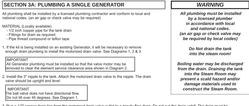
SECTION 3A: PLUMBING A SINGLE GENERATOR
All plumbing shall be installed by a licensed plumbing contractor and conform to local and national codes. (an air gap or check valve may be required)
MATERIAL (Locally available)
- 1/2 inch copper pipe for the tank drain - Fittings for drain as required
- Pipe thread compound or tefl on tape IMPORTANT
Detailed drain connection information is in the Installation Instructions packed with the Steam Generators. The instructions must be used to assure proper drain operation.
1. If this is an old installation being upgraded, it can require up to three (3) automatic drain valves, one per generator. IMPORTANT
If additional drain valves or automatic drain valve kits are required, call the Technical Support Department at 1-800-363-0251. 2. Install all automatic drain valves. All valves should be installed as shown in Diagrams 1 thru 6.
IMPORTANT
All motorized drain valve outlets must be within six (6) feet and one (1) 90° bend of the site gravity drain. Use pipe thread compound or tefl on tape on all threaded fi ttings.
All plumbing must be installed by a licensed plumber in accordance with local
and national codes. (an air gap or check valve may
be required by local codes) Do Not drain the tank
into the steam room! Boiling water may be discharged from the drain. Draining the tank
into the Steam Room may present a scald hazard and/or
damage materials used to construct the Steam Room.
SECTION 3B: PLUMBING MULTIPLE GENERATORS
All plumbing shall be installed by a licensed plumbing contractor and conform to local and national codes. (an air gap or check valve may be required)
MATERIAL (Locally available)
- 1/2 inch copper pipe for the tank drain - Fittings for drain as required
- Pipe thread compound or tefl on tape
1. If the kit is being installed on an existing Generator, it will be necessary to remove enough drain plumbing to install the motorized drain valve. See Diagrams 1, 2 & 3. IMPORTANT
All Generator plumbing must be installed so that the valve motor may be removed to clear the element service clearance area shown in Diagram 2.
2. Install the 3" nipple to the tank. Attach the motorized drain valve to the nipple. The drain valve should be upright and level.
IMPORTANT
The ball valve does not have directional fl ow. Do not tilt over 45 degrees. See Diagram 1.
3. Run a 1/2" copper drain line from the motorized drain valve outlet to a gravity fl ow drain. Do not run the drain uphill. The drain must be connected in accordance with local and national codes.
WARNING
SECTION 4: MOUNTING THE DRAIN VALVE'S MOTOR
The drain valve is designed so its motor may be easily removed to facilitate installation and ser-vice. Before removing or installing the motor, make sure the lever (used to manually
DIAGRAM 7
DIAGRAM 8
Manual Lever
DIAGRAM 11
DIAGRAM 10
DIAGRAM 9
All electrical supplies to the Generator should be discon-nected before and during
instal-lation of this kit. User Shock Hazard! 208-240V
wires attached to this Option must be routed per these
in-structions.
User Shock Hazard! If existing wiring is disturbed assure that the fi nal installation conforms with generator wiring diagram.
Conduit must be used when installing drain valve to connect
the valve to ground.
WARNING
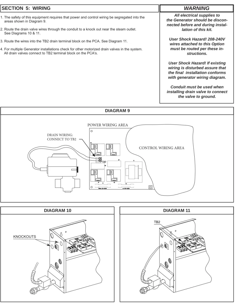
SECTION 5: WIRING
1. The safety of this equipment requires that power and control wiring be segregated into the areas shown in Diagram 9.
2. Route the drain valve wires through the conduit to a knock out near the steam outlet. See Diagrams 10 & 11.
3. Route the wires into the TB2 drain terminal block on the PCA. See Diagram 11. 4. For multiple Generator installations check for other motorized drain valves in the system. All drain valves connect to TB2 terminal block on the PCA's.
TB2
KNOCKOUTS
DRAIN WIRING: CONNECT TO TB2
POWER WIRING AREA
1. Assure power and water are on.
2. Turn on the Generator(s) using the owner's control. Allow the tank(s) to fi ll completely. Adjust the bath temperature to a point at least 10°F (6C) above the current steam room temperature to ensure the steamer begins heating the water.
3. Turn off the Generator(s) using the owner's control.
4. Sixty minutes (60) after the Generator is turned off, the drain will open and close a few times and water will be added to the generator as needed to cool the water and drain the tank; this could take up to 15 minutes. Once the drain cycle is complete, the tank will remain empty until the next bath. No water should come out the steam head.
The unit is now ready for operation.
SECTION 6: OPERATIONAL TEST
There are no user serviceable parts in the Generator. All repair should be performed by a qualifi ed service person. For additional assistance or the factory authorized service person nearest you call Technical Support at 1-800-363-0251. The Troubleshooting Guide below is meant as a general aid only. Follow ACTION TO BE TAKEN in order until the problem is resolved.
SECTION 7: TROUBLESHOOTING GUIDE
SYMPTOMS
PROBABLE CAUSES
ACTION TO BE TAKEN
Drain Valve leaks Motor not secured to the valve or
Valve part way open or
Debris in valve or
Faulty PCA (Circuit Board)
Remount motor per Section 4
Make sure the motor’s manual lever is not latched open or sticking aginst an obstruction.
Clean valve
Remove wires from PCA. If leak stops the PCA may be faulty. If leak continues, check steps above.
NOTE: The ADT Drain Valves are normally closed. They open only when engergized by the steam generator. These valves are ball valves and are not directional.
Water does not run out of the drain.
Manual drain valve closed or
Valve or drain piping plugged or
Faulty Drain Valve
or
Faulty PCA (Circuit Board) Water runs out steam
outlet during drain cycle. Faulty PCA PCA or steamer faulty; Contact Support at 1-800-363-0251 Make sure any manual valves in the drain piping are open Clean valve and piping
Make sure the motor’s manual lever can move freely and is moving when the valve should be opening. If it does not move, check wiring. Call technical support at 1-800-363-0251. If steamer is not operating, check the 1A fuse on the PCA. Otherwise, contact Technical Support at 1-800-363-0251.