Group of Experts for the revision of the IMO/ILO/UNECE
Guidelines for Packing of Cargo Transport Units
Fourth session
Geneva, 4 – 6 November 2013
Draft Informative Material
1. The secretariat reproduces hereafter the draft informative material developed by the Group of Experts for the revision of the IMO/ILO/UNECE Guidelines for Packing of Cargo Transport Units.
2. The informative material provides practical guidance and background information on the packing of cargo transport units. It may be used as a supplement to the IMO/ILO/UNECE Code of Practice for Packing of Cargo Transport Units (CTU Code). 3. Detailed information on the development of the informative material is available in the report of the fourth session (Informal document EG GPC No. 19 (2013) at www.unece.org/trans/wp24/guidelinespackingctus/intro.html).
4. The CTU Code is available in Informal document ITC (2014) No. 7 at www.unece.org/trans/main/itc/itc_inf_76.html.
Informal
document EG GPC No. 20 (2013)Distr.: Restricted 29 January 2014
Informative Material
January 2014
DRAFT
Table of Contents
IM 1 Consequences of improper packing procedures
IM 2 Typical documents related to transport
IM 3 CTU types
IM 4 Species of concern regarding recontamination
IM 5 QUICK LASHING GUIDE
IM 6 Intermodal load distribution
IM 7 Manual handling
IM 8 Transport of perishable cargo
IM 9 CTU seals
Informative material 1
Consequences of improper packing procedures
1
Consequences of badly packed and secured cargo
1.1 Cargo which has not been properly packed and sufficiently secured in a CTU may move inside the unit when it is exposed to acceleration, e.g. by hard braking of a vehicle on the road or by heavy ship motions at sea. Moving cargo resulting from improper securing may cause accidents, damage to the cargo, to other cargo or to the CTU. In particular heavy cargo items may develop inertia forces under such traffic accelerations, which may let them break through the CTU boundaries, menacing persons, environment or property of third parties.
Figure 1.1 Lack of longitudinal securing Figure 1.2 Inadequate side wall strength 1.2 Figure 1.1 shows an example where hard braking and a lack of longitudinal securing has
resulted in the cargo breaking through the container doors. Figure 1.2 shows a second example where the cargo has been secured against a vehicle side with inadequate strength. 1.3 Cargo breaking out of CTUs is of particular danger on board RO/RO vessels, where shifting
cargo and CTUs may affect safe operations on the vehicle deck or the stability of the ship (see figures 1.3 and 1.4).
1.4 Cargo having broken out of a trailer has caused other trailers to shift and the vessel to get a heavy list (see figure 1.5)
1.5 Damage to the cargo is always an economic loss. Additionally, in case of dangerous goods, any damage to a receptacle may impair its containment capability and cause spillage of the contents (see figure 1.8), thus endangering persons and affecting the safety of the transport vehicle or ship.
Figure 1.6 Unsecured packages Figure 1.7 Loose packages on rail wagon 1.6 Spilled cargo may also endanger the environment. Cargo from road or rail transport may
cause contamination of the soil and/or water, and marine pollution when released at sea.
Figure 1.8 Spilled liquid dangerous goods Figure 1.9 Broken IBCs
2
Consequences of insufficient control of humidity
2.1 Some CTUs like containers present a closed box with a specific micro climate. During a long distance transport the moisture contained in the goods and in the packaging material including any timber used for blocking and protection may condense on the inner boundaries of the container or on the cargo or even within the cargo. If sensitive goods are packed carelessly into such a closed CTU, mainly box containers for sea transport, metal parts, if not properly protected, may corrode, clean surfaces may be stained and organic materials may suffer from mould or rot or other degradation.
2.2 In particular hygroscopic cargoes have variable water content. In ambient air of high relative humidity, they absorb water vapour, while in ambient air of low relative humidity, they release water vapour. If packed into a container in a climate of high relative humidity they would bring a considerable amount of water into the container, providing for an internal high relative humidity. This water may be released from the goods during temperature changes and may condense with the above mentioned consequences. If this threat has not been averted by pre-drying the cargo to a so-called "container-dry" state, the high water content may result in mould, rot and biochemical changes. For some products, these phenomena are also associated with self-heating, which may go as far as spontaneous combustion, for example with oil seeds, oil seed expellers and fish meal.
3
Consequences of the use of unsuitable CTUs
3.1 A CTU should be suitable for the particular cargo to be packed:
• climatically sensitive cargoes may require ventilated containers or a CTU with controlled atmosphere (reefer or heated container)
• heavy packages or packages with small footprints may require CTUs capable of carrying concentrated loads
• dry bulk powders and granules may require CTUs with stronger end walls to avoid structural failure, overloading, serious damages or cargo losses.
3.2 CTUs showing structural deficiencies may fail under normal transport conditions, e.g. the bottom of a damaged container may collapse when the container is lifted, the front wall of a damaged road vehicle may give way upon hard braking or goods in a container with leaking roof may suffer from water ingress. This makes a thorough pre-check of each CTU essential before packing commences.
4
Consequences of overloading of CTUs
4.1 A CTU overloaded by excess mass presents a serious threat to the safety of work of the various persons along the chain of transport, who are in charge of handling, lifting or transporting the CTU. This applies to all modes of transport on road, rail and sea.
4.2 There are many hazards associated with an overloaded CTU: 4.2.1 When loading or unloading the CTU on or
off a ship, vehicle or rail-car and handling the CTU by mobile lifting equipment in a terminal area may result in a failure of the lifting equipment.
4.2.2 While attempting to lift an overloaded CTU from a ship, vehicle or rail-car, the lifting equipment may have inadequate lifting capacity and the lift fails (see figure 1.14) or is aborted. An unacceptable delay will occur while a replacement device with greater capacity is sourced.
4.2.3 Where cranes and lifting equipment are equipped with weight limit controls such failures may not occur, however, as these controls are designed to protect the crane from overstressing, they may not detect that the CTU is overloaded. As a consequence the overloaded CTU will enter the transport chain and may cause an accident where the CTU turns over or falls from the transport equipment.
4.3 A CTU that is not overloaded, i.e. the gross mass of the CTU is less than the maximum permissible mass of the CTU, may be packed with cargo so that the gross mass exceeds the permissible gross mass of the transport vehicle. This hazard may be aggravated by the road vehicle’s driver being unaware of the excess mass, and as a consequence may not adjust his driving habits accordingly. A similar hazard may arise from the specific conditions in intermodal road/rail transport, as rail wagon design does not provide for a sufficient overweight safety margin.
4.4 In view of the above, all efforts should be taken to prevent exceeding the maximum gross mass of the CTU or the capacity of the transport medium. However, if a unit is found to be overloaded or overweight, it should be removed from service until it has been repacked to its maximum gross mass.
4.5 Where there are no facilities for lifting and / or repacking an overloaded or overweight CTU, the CTU operator should arrange transport under the supervision of transport authorities back to the nearest facility where repacking can be undertaken.
5
Consequences of improper documentation and misdeclaration
5.1 Missing or incomplete documentation may hamper the proper planning or executing the packing of a CTU. It may also interfere with the further transport and generate delays and thereby economic losses. This applies also to the correct and timely communication of non-technical information like the identification number or the seal number.
5.2 Missing information to the carrier identifying extraordinary cargo properties, such as out of gauge packages (over-height, over-width or over-length), overweight or offset of centre of gravity, may cause damage to the cargo due to inadequate handling methods that could not be adjusted to meet the unusual properties of the packed CTU.
5.3 Missing or incorrect information on dangerous goods may lead to improper stowage of the CTU on the transport vehicle, in particular a ship. In case of an incident such as spillage or fire, missing dangerous goods information will impede emergency response actions.
5.4 Inadequately packed containers or misdeclared container weights declaration may cause container stacks to collapse.
Figure 1.16 Stack failure
5.6 Incorrect gross mass declared for a CTU could result in overloading of a road vehicle or a rail car, especially if two or more units are loaded on one vehicle or one rail car. In case of sea transport, improper mass declaration of a container may result in an improper stowage position on board the ship and thereby in a fatal overstressing of the securing equipment for a stack of containers.
Informative material 2
Typical documents related to transport
1
The CMR note (Road transport)
The CMR note is the consignment note through which the CMR Convention is applied to international road haulage when at least one of the countries is a Contracting country to the Convention. There are only a very few specific exemptions. Existence of the CMR note confirms that the carrier (i.e. the transport company) has received the goods and that a contract of carriage exists between the consignor/trader and the carrier. If CMR applies to a contract it provides all parties to the contract with the complete regime for the determination of their rights, obligations, liabilities and remedies, in respect of claims for loss, damage or delay to the goods. Unlike a bill of lading, a CMR is not a document of title or a declaration, although some States regard it as such. It does not necessarily give its holder and/or the carrier rights of ownership or possession of the goods, which will be decided by the courts on a case-by-case basis.
2
Forwarders certificate of receipt (FCR) (all modes of transport)
2.1 The Forwarders Certificate of Receipt was introduced for the use of international freight forwarders. The FCR document enables the freight forwarder to provide the consignor with a special document as an official acknowledgement that he has assumed responsibility of the goods.
2.2 By completing the FCR the freight forwarder certifies that he is in possession of a specific consignment with irrevocable instructions for despatch to the consignee shown in the document or for keeping it at his disposal. These instructions may only be cancelled if the original FCR document is handed over to the issuing freight forwarder and only if he is in a position to comply with such cancellation or alteration.
2.3 The FCR will primarily be used when the supplier sells the goods ex works and needs to prove that he has complied with his obligations to the buyer by presenting a FCR. In the case of a Letter of Credit the seller will under such conditions be able to present a FCR issued by a forwarder in order to obtain payment of the sales price placed at his disposal by the buyer under the terms of the Letter of Credit. The seller can no longer dispose of goods handed over to the forwarder once the FCR document has been handed over to the buyer.
2.4 The FCR is not negotiable. As the delivery of the consignment to the consignee does not depend on the handing over of this document, only one original is issued. Should further copies be required, forms specially overprinted with the words "Copy not negotiable" should be used.
Figure 2.1 CMR example
2.5 Another similar document, the Forwarders' Certificate of Transport (FCT), is negotiable. This means that the forwarder accepts responsibility to deliver to a destination you specify - not to an unchangeable destination as with the FCR.
3
CIM consignment note (Rail transport)
3.1 This document confirms that the rail carrier has received the goods and that a contract of carriage exists between trader and carrier.
3.2 Unlike a bill of lading, a CIM note isn't a document of title. It doesn't give its holder rights of ownership or possession of the goods.
3.3 Key details to be provided in the note include: 1. a description of the goods;
2. the number of packages and their weight; and 3. the names and addresses of the sender and
recipient.
3.4 The consignor is responsible for the accuracy of CIM notes, and is liable for any loss or damage suffered by the carrier due to inaccurate information. Notes are used to calculate compensation if goods are lost or damaged.
4
Export Cargo Shipping Instruction (ECSI) (Sea transport)
This document may be used to provide the shipping company with details of the goods and set out any specific instructions for the shipment. It follows up on the initial booking, when space will have been confirmed on particular sailings. The process is often concluded by telephone.
Figure 2.3 CIM example
5
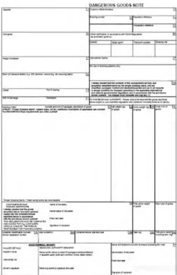
Dangerous Goods Transport Document (Sea transport)
5.1 If however, the goods are considered to be dangerous as per the IMDG Code, a Dangerous Goods Transport Document will be required. In some countries this document is also known as Dangerous Goods Note (DGN).
5.2 The Dangerous Goods Transport Document contains a section “Container / vehicle packing certificate”. This section must be completed by the person responsible for packing of the dangerous goods into the CTU, who may not necessarily be a representative of the shipper or consignor.
6
Bill of lading (Sea transport)
6.1 This is issued by the carrier and serves three purposes:
1. it shows that the carrier has received the goods; 2. it provides evidence of a contract of carriage;
and
3. it serves as a document of title to the goods. 6.2 There are a number of different types of Bill of
Lading some of which may be transmitted electronically.
Figure 2.6 BoL example Figure 2.5 DGN example
7
Multimodal bill of lading
7.1 Increasingly, international trade journeys are intermodal, with freight forwarders playing a crucial coordinating role. Many multimodal transports are handled with such a document. 7.2 The FIATA Multimodal Transport Bill of Lading (FBL) is a carrier-type transport document for
the use by freight forwarders acting as multimodal transport operators (MTO).
7.3 A freight forwarder acting as Multimodal Transport Operator (MTO) or marine carrier issuing a FBL is responsible for the performance of transport. The freight forwarder does not only assume responsibility for delivery of the goods at destination, but also for all carriers and third parties engaged by him for the performance of the whole transport.
8
Sea waybill (Sea transport)
This fulfils the same practical functions as the bill of lading, but does not confer title to the goods and is therefore quicker and easier to use. It's often used where there's a well-established trading relationship between buyer and seller or in transactions where ownership doesn't change hands, e.g. between divisions of a single company.
Informative material 3
CTU types
This informative material provides detailed information on the types of CTU available with the aim of providing packers and shippers with the best possible independent advice.
1
ISO containers
1.1 Containers – General
1.1.1 A container1 (freight container) is an article of transport equipment which is:
.1 of a permanent character and accordingly strong enough to be suitable for repeated use;
.2 specially designed to facilitate the carriage of goods by one or more modes of transport, without intermediate reloading;
.3 fitted with devices permitting its ready handling, particularly its transfer from one mode of transport to another;
.4 so designed as to be easy to pack and unpack; .5 having an internal volume of at least 1 m3 (35.3 ft3)
1.1.2 A container is further defined by the CSC2:
.1 designed to be secured and / or readily handled, having corner fittings for these purposes
.2 of a size such that the area enclosed by the four outer bottom corners is either:
• at least 14 m2 (150 ft2) or
• at least 7 m2 (75 ft2) if it is fitted with top corner fittings. 1.1.3 ISO container dimensions
Figure 3.1 ISO container sizes
1.1.4 In addition to the standard lengths there are regional / domestic variations which include 48-foot, 53-foot and longer.
1 ISO 830:1999 Freight containers - vocabulary
mm ft in mm ft in mm ft in 6 6 1EEE 1EE 45 L5 Freight container designation
Length, L Width, W Height, H
13,716 2,438 8 2,896 2,591 9 ISO Size Code L2 45ft long x 9ft 6in high
Freight container description
45ft long x 8ft 6in high
40ft long x 9ft 6in high 1AAA 45
8
40ft long x 8ft 6in high 1AA 42 2,591 8 6 2,896
9 6 12,192 40 2,438 8
30ft long x 9ft 6in high 1BBB 35 2,896 9 6 2,438
8 1,295
4 3 40ft long x 8ft high 1A 40
40ft long half height 1AX 48
30ft long x 8ft high 1B 30 11 ¼ 2,438 8 30ft long x 8ft 6in high 1BB 32 2,591 8 6
9,125 29 2,438 8
20ft long x 9ft 6in high 1AAA 25 2,896 9 6 30ft long half height 1BX 38 1,295 4 3
20ft long x 8ft high 1A 20 10 ½ 2,438 8 20ft long x 8ft 6in high 1AA 22 2,591 8 6
6,058 19 2,438 8
ISO Freight container sizes
10ft long half height 1AX 18 1,295 4 3 10ft long x 8ft high 1A 10 2,438 8
9 ¾
2,991 9 2,438 8
1.1.5 The standard width is 8 ft (2.438 mm), with regional variations of 8ft 6in (USA) and 2.5 m (Europe).
1.1.6 The ISO standard heights are half height (4ft 3in / 1,295 mm), 8ft (2,438 mm), 8ft 6in (2,591 mm) and 9ft 6in (2,896 mm).
• There are very few 8-foot high containers left in circulation
• Practically all 20-foot long containers are 8ft 6in high
• Practically all 45-foot long containers are 9ft 6in high
• Regional heights of 9 ft, 10 ft and 3 m can be found for specific cargoes. 1.1.7 Fork-lift pockets
• May be provided on 20-foot and 10-foot containers
• Are not generally fitted on 30-foot and longer containers.
• On 20-foot are generally fitted with for pockets with centres of 2,050 mm ±50 mm and may be used for lifting full containers. Some 20-foot containers may have a second set at 900 mm centres which are used for emptying lifting. However this design feature is now almost extinct.
1.2 General cargo containers for general purpose (ISO 1496 part 1) Containers built to this international standard includes:
• Dry freight (box) container
• Dry freight with bulk capabilities
• Ventilated container
• Open top container
• Open side container
• Named container 1.2.1 Dry freight containers
1.2.1.1 A general purpose container (also known as a GP or dry van) is a container which is totally enclosed and weather-proof. It generally will have a corten steel frame with a rigid roof, rigid side walls, rigid end walls at least one of which is equipped with doors, and a floor. It is intended to be suitable for the transport of cargo in the greatest possible variety.
1.2.1.2 It is not intended for the carriage of a particular category of cargo, such as cargo requiring temperature control, a liquid or gas cargo, dry solids in bulk, cars or livestock or for use in air mode transport.
Figure 3.2 20’ GP Figure 3.3 40' GP Figure 3.4 45' GP 1.2.1.3 The GP container is by far the largest container type in the intermodal fleet comprising
about 90% of the ISO series I (maritime) fleet. The 20ft x 8ft 6in GP container is the largest single container type forming just under half of the GP fleet and about 40% of all container types and sizes.
1.2.1.4 Dimensions and volume
• There are very few 20-foot long x 9ft 6in high GP containers
• There are very few 45-foot long GP container that are not 9ft 6in high. GP containers with lower heights can be considered as unavailable.
.1 Minimum internal dimensions and volume
Figure 3.5 Table of internal dimensions .2 Minimum door openings
• 9ft 6in high – 2,566 mm high x 2,286 mm wide.
• 8ft 6 in high – 2,261 mm high x 2,286 mm wide
• 8ft high – 2,134 x 2,286 mm wide .3 Rating and load distribution
• 20-foot long GP containers generally have a maximum gross mass greater than 30,000 kg. The ISO standard was 30,480 kg, but this has been increased to 32,500 kg.
• 40-foot and 45-foot GP containers generally have a maximum gross mass of 32,500 kg or 34,000 kg
• Loads should be distributed across the flooring (see table below):
Figure 3.6 Guide for load distribution 1.2.1.5 Strengths and ratings
.1 Wall strengths
• side walls - 0.6P evenly distributed over the entire side wall
• front and rear walls – 0.4P evenly distributed over the entire wall.
Walls are tested to withstand the above load so that there is no or limited plastic (permanent) deformation. Walls that are tested and found to have a greater plastic deformation will be down rated and this will be marked on the CSC safety approval plate. Line 7 and / or 8 will be marked with end wall and side wall strength respectively, if it is lesser or greater than the standard load.
mm ft in mm ft in mm ft in m3 ft3
45ft long x 9ft 6in high 1EEE 2,655.0 8 9 ½ 83.6 3,068 45ft long x 8ft 6in high 1EE 2,350.0 7 9 ½ 74.0 2,719 40ft long x 9ft 6in high 1AAA 2,655.0 8 9 ½ 74.2 3,043 40ft long x 8ft 6in high 1AA 2,350.0 7 9 ½ 65.7 2,697 40ft long x 8ft high 1A 2,197.0 7 2 ½ 61.4 2,495 40ft long half height 1AX 1,054.0 3 6 ½ 29.5 1,236 30ft long x 9ft 6in high 1BBB 2,655.0 8 9 ½ 55.2 2,007 30ft long x 8ft 6in high 1BB 2,350.0 7 9 ½ 48.9 1,779 30ft long x 8ft high 1B 2,197.0 7 2 ½ 45.7 1,646 30ft long half height 1BX 1,054.0 3 6 ½ 21.9 809 20ft long x 9ft 6in high 1AAA 2,655.0 8 9 ½ 36.3 1,220 20ft long x 8ft 6in high 1AA 2,350.0 7 9 ½ 32.1 1,081 20ft long x 8ft high 1A 2,197.0 7 2 ½ 30.0 1,000 20ft long half height 1AX 1,054.0 3 6 ½ 14.4 491 10ft long x 8ft high 1A 2,197.0 7 2 ½ 14.3 235 10ft long half height 1AX 1,054.0 3 6 ½ 6.9 115
7 7 ¾ 5,867 19 3 2,330 7 7 ¾ 44 4 ⅜ 7 7 ¾ 2,330 7 ¾ ISO Freight container internal dimensions
Volume, V 9 2 5/ 16 2,330 7 2,802 8,931 29 3 ⅝ 2,330 11,998 39 4 ⅜ Height, H 13,522 Freight container description Freight container designation Length, L Width, W 2,330 7 7 ¾
30480
32500
34000
30480
32500
34000
45ft
2.25
2.40
2.51
967
1,032
1,079
40ft
2.54
2.71
2.83
1,090
1,163
1,216
20ft
5.20
5.54
5.80
2,230
2,377
2,487
Mass (kg) per m
2)
Length
Mass (tonnes) per linear m
.2 Floor strength
• The floor is tested using a vehicle equipped with tyres, with an axle load of 7,260 kg (i.e. 3,630 kg on each of two wheels). It should be so arranged that all points of contact between each wheel and a flat continuous surface lie within a rectangular envelope measuring 185 mm (in a direction parallel to the axle of the wheel) by 100 mm and that each wheel makes physical contact over an area within this envelope of not more than 142 cm2 . The wheel width should be
nominally 180 mm and the wheel centres should be nominally 760 mm. The test vehicle should be manoeuvred over the entire floor area of the container. The width of the test load is limited to the overall width of the wheels. The test should be made with the container resting on four level supports under its four bottom corner fittings, with its base structure free to deflect.
• Annex II of the International Convention for Safe Containers requires that containers are subjected to point loads tests identical to the ISO test except with the test load limited to 5,460 kg.
The actual capacity of the floor will depend on the size and type of wheel used by the fork truck, wider and larger diameter wheels may permit larger axle loads. .3 Cargo securing systems (if provided)
• Anchor points are securing devices located in the base structure of the container.
• Lashing points are securing devices located in any part of the container other than their base structure.
• They are either fixed, hinged or sliding eyes, rings or bars.
Figure 3.7 Table of lashings in ISO container
• Each anchor point should be designed and installed to provide a minimum rated load of 1,000 kg applied in any direction. Many containers have anchor points with a rating of 2,000 kg.
• Each lashing point should be designed and installed to provide a minimum rated load of 500 kg applied in any direction.
1.2.1.6 Typical cargoes
.1 The 20-foot long GP container provides the most flexible of all the container types and sizes as it is capable of carrying denser materials and is often used to carry granite, slate and marble blocks.
.2 The GP container is used for such cargoes as dairy and other “clean” products which require the interior to be “as new” without corrosion and flaking paint. At the other end of the spectrum, the GP container may be used for corrosive materials, such as wet salted hides. It is important that consignors advise the container supplier of the cargo prior to its delivery so that the correct standard of container can be delivered.
.3 Packages can be loaded by hand and stacked across the container, lifted in using a counterbalance or pallet truck, or slid in on skids or slip sheets. When loading using a counterbalance truck, it is important that the axle loads do not exceed the maximum permitted and that the cargo is distributed evenly.
40ft
30ft
20ft
10ft
Anchor points
8
6
5
4
Lashing points
Number of lashings per side
.4 GP containers are also used to transport cars and small vans either driven and secured to the floor, or secured to specialist racking that can be fitted and removed from the container without any modifications.
Figure 3.11 Individual cars Figure 3.12 Car racks
Figure 3.13 Solid bulk Figure 3.14 Bulk liquid .5 The GP container is also becoming a major transporter of bulk powders, granules
and liquids, within dry liner bags or flexitanks. 1.2.1.7 Variations
.1 There are few variations to the basic GP container, some 40-foot GP containers are built with a door at each end. The example shown in Figure 3.15 shows the doors above the gooseneck tunnel and fork pockets for handling when empty.
Figure 3.15 40-foot 8ft 6in high double ended container Figure 3.16 With doors open
.2 Another variant to the general purpose container is the pallet-wide container. These units have end frames that comply with the requirements of the series 1 ISO freight container, but can accommodate two 1,200 mm wide pallets across the width of the container. This is achieved through a design where the side walls are thinner and moved outside of the ISO envelope.
• Pallet-wide containers may not be fitted with anchor points and only have a limited number of lashing points.
1.2.2 Dry freight with bulk capabilities (see also 1.5.4)
1.2.2.1 These are dry freight fitted with loading hatches in the roof and / or discharge hatches in the end walls.
1.2.2.3 The lashing points along the roof may be fitted with hooks that may only be used to support the bulk liner bag.
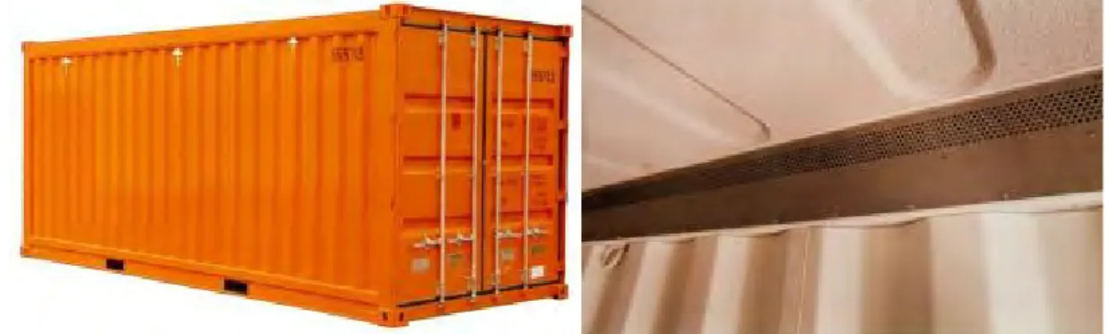
1.2.3 Closed vented or ventilated containers
1.2.3.1 A closed vented or ventilated container is a closed type of container similar to a general purpose container but designed to allow air exchange between its interior and the outside atmosphere. It will be totally enclosed and weatherproof, having a rigid roof, rigid side walls, rigid end walls and a floor, at least one of its end walls equipped with doors and that has devices for ventilation, either natural or mechanical (forced)
Figure 3.17 20-foot passive ventilated container Figure 3.18 Ventilated container inner grill 1.2.3.2 Vented containers are containers that have passive vents at the upper part of their cargo
space. While most containers built now are fitted with two or more vents fitted in the front or side walls, ventilated containers are containers which have a ventilating system designed to accelerate and increase the natural convection of the atmosphere within the container as uniformly as possible, either by non-mechanical vents at both the upper and lower parts of their cargo space, or by internal or external mechanical means.
1.2.3.3 This is a very specialised piece of equipment and was quite popular in the 1990’s with in excess of 5,000 in service.
1.2.3.4 Dimensions and volume
All ventilated containers are 20-foot long and 8ft 6in high. 1.2.3.5 Minimum internal dimensions and volume
Similar to the 20-foot GP Container 1.2.3.6 Minimum door openings
Similar to the 8ft 6in high GP containers 1.2.3.7 Rating and load distribution
The latest production of ventilated containers was built with a maximum gross mass of 30,480kg.
1.2.3.8 Strengths and ratings Similar to the GP container. 1.2.3.9 Typical cargoes
Ventilated containers were developed to carry green coffee beans and other agricultural products. Produce such as melons, oranges, potatoes, sweet potatoes, yams and onions are sometimes carried in ventilated containers.
1.2.3.10 Variations
Most ventilated containers have ventilation grills built into the top and bottom side rails and the front top rail and bottom sill. To further improve the movement of air though the container an electrical fan can be mounted in the door end and connected up to shore and ships’ supply. After the cargo has been delivered the fan can be removed and the fan
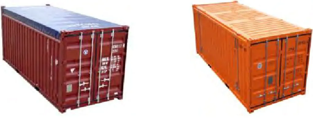
1.2.4 Open top containers
1.2.4.1 An open top container is similar to a general purpose container in all respects except that it has no permanent rigid roof. It may have a flexible and movable or removable cover, e.g. of canvas, plastic or reinforced plastic material often referred to as a Tarpaulin, “tarp” or “Tilt”. The cover is normally supported on movable or removable roof bows. In some cases the removable roof is fabricated from steel that can be fitted to lift off from the top of the container. Containers thus built have been known as ‘solid top’ containers.
Figure 3.19 20-foot open (soft) top container Figure 3.20 20-foot open hard top container 1.2.4.2 The open top container is designed to operate with the tarpaulin or hard top fitted or not
fitted, therefore to withstand the loads exerted onto the side walls the top side rails are substantially larger than those of a GP container. For the traditional open top container, the top side rail also has to accommodate receptacles for the roof bows and loops for attaching the tarpaulin. It is essential that the tarpaulin is the correct design and the eyelets on the tarpaulin match the eyes on the top side rail, front and back rails and around the corner fittings to ensure the best weathertightness and to permit the TIR wire to be threaded through all of them to maximise security.
1.2.4.3 The open top container was designed for two categories of cargo, those that are too heavy or difficult to load by conventional methods through the doors, or that are too tall for a standard GP container. The hard top, open top container caters for the former but due to the rigid roof, transporting tall cargoes may present problems with moving the roof to the destination.
1.2.4.4 The other feature of the open top container is the ability to pack tall items into the container through the doors, as the header (transverse top rail above the doors) is generally movable or removable (known as swing header). The swinging header either forms a trough into which the tarpaulin is attached or it folds over the front face of the header to prevent water runoff from entering the container. The header is held in place by hinges at each end adjacent to the corner fittings, and each hinge has a removable pin that so that the header can be swung out of the way. However it is advisable to remove both pins and lift the header down using a fork truck rather than leaving the header unsupported at one end.
Figure 3.21 20-foot open top with tilt removed and rear header open
1.2.4.5 Open tops are generally 20-foot or 40-foot long and 8ft 6in high. There are a few 9ft 6in high to cater for some cargoes and which will enable standard tarpaulins or hard tops to be used.
1.2.4.6 Dimensions and volume
With the exception of the removable tarpaulin, roof, the dimensions are generally in line with the GP container.
1.2.4.7 Minimum internal dimensions and volume Similar to the GP Container
1.2.4.8 Minimum door openings
Similar to the 8ft 6in high GP containers 1.2.4.9 Rating and load distribution
As GP container. 1.2.4.10 Strengths and ratings
Similar to the GP container. 1.2.4.11 Typical cargoes
Open top containers carry a variety of tall and heavy, generally project type cargo. Regular cargoes include glass sheets mounted on special A frames often lifted in through the roof and covered using an over height tarpaulin, large diameter tyres .for mine vehicles and scrap steel.
Figure 3.22 20-foot open top with scrap steel Figure 3.23 20-foot open top with extra large tyres
1.2.4.12 Variations
There are a few variations from the standard tarpaulin covered open top container. Many designs have been developed to ease the fitting and removal of the tarpaulin roof and roof bows. These include sliding tarpaulins which concertina towards the front of the container and captive roof bows that lift out on one side and hand from a bar on the other, thus reducing the risk of loss when an over height cargo is carried.
Figure 3.24 20-foot coil carrier Figure 3.25 40-foot ingot and bar carrier Hard top open top containers have been adapted to carry large steel coils or long bars.3
1.2.5 Open side containers
1.2.5.1 The open side container was introduced into the maritime fleet as a GP container variation and as an alternative to the standard curtain sided trailer used in road transport. Original designs had a curtain on one or both sides, a rigid roof and rear doors. Without side walls the base structure had to be self-supporting, therefore required to be more substantial than the GP floor to achieve the same floor strength and load carrying capabilities. In this form the open side container took on some of the characteristics of the platform based container with complete superstructure4. As a consequence of the self-supporting floor the tare generally increased.
1.2.5.2 To improve security some manufacturers offer solid doors in place of the curtains offering doors to one or both sides, with no rear doors, with doors at the rear of the container and with door at the front of the container, offering one, two, three and four side access.
1.2.5.3 The open side container is a specialist item of transport equipment, although the 45-foot long and 2.5 m wide pallet-wide curtain side variation is becoming more popular in Europe. However the full length side door 20-foot long unit is also becoming popular as a regional variation in other parts of the world.
Figure 3.26 45-foot curtain sided swap body Figure 3.27 20-foot side door container 1.2.5.4 Dimensions
As GP container.
1.2.5.5 Minimum internal dimensions and volume
Similar to the GP Container although the internal height is reduced to approximately 2.4 m. 1.2.5.6 Minimum door openings
Reduced height to match the reduction of internal height. 1.2.5.7 Rating and load distribution
Maximum gross mass is generally 34,000 kg for newer 45-foot long units. 20-foot units will be 30,480 kg or higher.
1.2.5.8 Strengths and ratings .1 Wall strengths
• side walls – Refer to CSC safety approval plate. Open side containers with tarpaulin sides may have little (0.3P) or no strength, however some are fitted with removable gates or rigid side doors which may achieve full side wall strength (0.6P).
• front and rear walls – 0.4P evenly distributed over the entire wall. .2 Floor strength
• as GP container. .3 Cargo securing systems
• Anchor points may be recessed onto the floor but may be rated lower than standard GP containers. Please check with CTU operator.
1.2.5.9 Typical cargoes
Open side containers are designed to carry packages that can be loaded using a fork truck, typically pallets and long packages.
1.2.5.10 Variations
Variations are available for specific trades, such as an open side container with a built in half height deck.
Other variations include internal full length or partial length central walls to provide support to the base structure and assist with pallet placement.
Figure 3.28 20-foot open side with mezzanine deck 1.2.6 Named cargo containers
1.2.6.1 Named cargo types of containers are containers built in general accordance with ISO standards either solely or principally for the carriage of named cargo such as cars or livestock.
Figure 3.29 Double height car carrier Figure 3.30 Single height car carrier
Figure 3.31 Livestock carrier Figure 3.32 Genset container
1.2.6.2 One particular container type is the Power Pack, which can be used to supply 3 phase electricity to reefer containers when carried by rail, to supplement or provide power on board during sea transport or to supplement or provide power in terminals.
1.2.6.3 A power pack would typically consist of a diesel generator set (250kW-700kW) with up to 64 sockets. They can include built in fuel tanks for the generator or use a 20-foot tank container carried in an adjacent slot.
1.3 Thermal containers (ISO 1496 part 2)
1.3.1 A thermal container is a container that has insulating walls, doors, floor and roof. Over the years the thermal container has evolved from a simple insulated container with no device for cooling and/or heating to a refrigerated and insulated container cooled using expendable refrigerants such as ice, 'dry ice' (solid carbon dioxide), or liquefied gasses but again with no external power or fuel supply.
1.3.2 A variation of this design is the porthole container, which is refrigerated by cold air from an external source introduced through a porthole. This design is being phased out.
1.3.3 The most common variant of the thermal container is the integrated refrigerated container, often referred to as the “Reefer”. The internal temperature is controlled by a refrigerating appliance such as a mechanical compressor unit or an absorption unit. The Reefer consists of a container body with insulated walls, sides and roof plus insulated doors at the rear. The front of the container body is left open for mounting the refrigeration machinery.
Figure 3.33 20-foot refrigerated container Figure 3.34 40-foot refrigerated container 1.3.4 Refrigeration machinery is generally powered by 3-phase electricity supplied by a trailing
lead that can be connected to sockets on board ship or in the terminal. Where there is insufficient power capacity freestanding “power packs” can be used. Power packs can also be used to supply power to a number of Reefers being carried by rail. When the Reefer is to be carried by road, unless the journey is relatively short, most cargo owners will require the reefer to be running and for this nose mounted or trailer mounted generator sets are available.
1.3.5 There are some refrigerated containers fitted with integrated power packs, fitted with a diesel generator negating the need for a standalone generator. However the volume of diesel that these containers can carry is limited and needs to be monitored regularly. These are very specialist pieces of equipment and used on closed loop trades, and are not generally available.
1.3.6 Where reefers are used to transport chilled or frozen cargo by road, some owners have integral refrigerated containers with the machinery including a diesel generator.
1.3.7 The refrigeration machinery works by passing air through the container from top to bottom. In general, the "warm" air is drawn off from the inside of the container, cooled in the refrigeration unit and then blown back in the container as cold air along the “T” floor grating. 1.3.8 To ensure adequate circulation of the cold air, the floor is provided with “T” section gratings.
Pallets form an additional space between container floor and cargo, so also forming a satisfactory air flow channel.
1.3.9 The last form of thermal containers are those that can operate within areas with low or very low ambient temperatures, often servicing areas of extreme cold such as Alaska. The design of these can be based on a thermal as described above except with a heating device, or by the use of a general purpose container fitted with internal insulation and heating filaments. 1.3.10 The mix of reefer units has changed over the last few years, new purchases of 20-foot and
40-foot long 8ft 6in high reefer containers has not matched the number of sales of old units, therefore the fleet size is shrinking. On the other hand the 40-foot 9ft 6in high reefer has been growing with 150,000 added to the fleet in recent years.
1.3.11 Dimensions and volume
1.3.12 Typical internal dimensions
Figure 3.35 ISO reefer container dimensions
The dimensions shown above are typical for a steel reefer unit, however packers are advised to contact the CTU operator for exact internal dimensions,
1.3.13 Door openings
• Each thermal container should be provided with a door opening at least at one end.
• All door openings and end openings should be as large as possible.
• The usable width should correspond with the appropriate minimum internal dimension given in Figure 3.35.
• The usable height should be as close as practicable to the appropriate minimum internal dimension given in Figure 3.35.
1.3.14 Table 3.Rating and load distribution
The latest production of 20-foot reefers has a maximum gross mass of 30,480 kg and 40-foot and 45-foot long a maximum gross mass of 34,000 kg
1.3.14.1 Strengths and ratings .1 Wall strengths
• side walls - 0.6P evenly distributed over the entire side wall
• front and rear walls – 0.4P evenly distributed over the entire wall.
Walls are tested to withstand the above load so that there is no or limited plastic (permanent) deformation. Walls that are tested and found to have a greater plastic deformation will be down rated and this will be marked on the CSC safety approval plate. Line 7 and / or 8 will be marked with end wall and side wall strength respectively, if it is lesser or greater than the standard load.
2. Floor strength
• The floor is tested using a vehicle equipped with tyres, with an axle load of 5,460 kg (i.e. 2,730 kg on each of two wheels). It should be so arranged that all points of contact between each wheel and a flat continuous surface lie within a rectangular envelope measuring 185 mm (in a direction parallel to the axle of the wheel) by 100 mm and that each wheel makes physical contact over an area within this envelope of not more than 142 cm2. The wheel width should be nominally 180 mm and the wheel centres should be nominally 760 mm. The test vehicle should be manoeuvred over the entire floor area of the container. The width of the test load is limited to the overall width of the wheels. The test should be made with the container resting on four level supports under its four bottom corner fittings, with its base structure free to deflect.
The strength of the floor will depend on the size and type of wheel used by the fork truck, wider and larger diameter wheels may permit larger axle loads.
Mechanical handling equipment with narrow wheels may damage the “T” section flooring, and wherever possible the width of the wheels should be greater than twice the distance between centre lines of “T” sections.
.3 Cargo securing systems
mm ft in mm ft in mm ft in m3 ft3
45ft long x 9ft 6in high 1EEE 13,115 43 ¼ 2,294 7 6 ½ 2,554 8 4 ½ 81.5 2,878 40ft long x 9ft 6in high 1AAA 2,554 8 4 ½ 67.9 2,398 40ft long x 8ft 6in high 1AA 2,350 7 9 ½ 62.5 2,697 20ft long x 9ft 6in high 1AAA 2,554 8 4 ½ 32.0 1,003 20ft long x 8ft 6in high 1AA 6 ½ 2,350 7 9 ½ 29.5 1,081
11,590
38 2,294 7 6 ½ 5,468
17 11 2,294 7
ISO Refrigerated container internal dimensions
Freight container description
Freight container designation
1.3.15 Typical cargoes
Reefer containers were developed to transport perishable cargoes. A "perishable" may be described as something that is easily injured or destroyed. Without careful treatment, the time taken to deteriorate to a condition which will either reduce the value or render it unsaleable (shelf life) may become unacceptably short.
Careful consideration of the factors affecting the "shelf life" of perishables should be made and applied during their transport.
Perishables include frozen produce, meats, seafood, dairy products, fruit and vegetables, horticultural products such as flowering bulbs and fresh flowers plus chemical compounds and photographic materials.
1.3.16 Variations
Reefers can be fitted with a number of refrigeration units from different suppliers and those can also provide controlled atmosphere provisions.
Structurally, special designs have been produced for rail based equipment, 48, 53 and 58-foot long and over wide units (2.6 m).
1.4 Tank containers for liquids, gases and pressurised dry bulk (ISO 1496 part 3)
1.4.1 A tank container comprises two basic elements, the tank (barrel) or tanks and the framework and complies with the requirements of ISO 1496-3.5
1.4.2 In the freight container industry, the term “tank” or “tank container” usually refers to a 20-foot tank container consisting of a stainless steel pressure vessel supported and protected within a steel frame.
1.4.3 The tank container industry has developed a number of containment designs that carry all sorts of bulk liquids, powders, granules and liquefied gases, however it is important to differentiate bulk liquid and pressurised dry bulk tank containers from non-pressured dry bulk containers that may look very similar to a tank container.
1.4.4 The majority of the maritime tank container fleet is 20-foot long and 8ft 6in high. The split between the major tank designs is not known although the most current production is generally Collar tanks. All the tank designs fulfil the requirements of the ISO standards. 1.4.5 Designs
There are three main structural types of tank container used in the international transport of bulk liquids and liquefied gases - beam, frame and collar. All designs have been manufactured since the 1970s.
All designs can be top lifted, must be stackable and the pressure vessel / barrel as well as all valves and other service equipment must remain within the ISO envelope, i.e. no part can protrude past the outer faces of the corner fittings.
1.4.5.1 Frame Tanks
This design consists of two end frames separated by two main beams at low level forming a support frame. Since there is more material in the support frame than with other designs the tare is relatively high. Often the lower beams are “castellated” a method of lightening the main beams by cutting holes to reduce the tare and therefore to increase the payload. Top rails are often light weight, play little part in the overall structural strength and often there to support the walkway. Top rails in these cases are not usually attached to the pressure vessel. In some designs these rails can be attached using mechanical fasteners (nuts and bolts) but are more often welded in place.
The pressure vessel is supported from the main beams generally on saddle supports which are in the form of bolted clamps or welded interface supports.
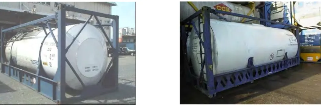
Figure 3.36 20,000 l frame tank Figure 3.37 25,000 l frame tank
The two pictures above show a 20,000 litre (Figure 3.36) and a 25,000 litre design (Figure 3.37). Both are insulated.
1.4.5.2 Beam Tanks
A beam tank is supported by a series of bearers attached to the end frames which interface with the pressure vessel at various locations on the periphery of the barrel. The interface consists of plates that are welded to the pressure vessel and the bearers to ensure load sharing and a “barrier” between carbon steel and stainless steel components. The example shown in Figure 3.38 is a typical beam tank with no top or bottom side rails. The tank is attached using four beams that connect at the four corner fittings of each end frame. The walkway is supported using brackets attached to the pressure vessel.
Figure 3.38 Beam tank no top rail Figure 3.39 Beam tank with top rail Figure 3.39 shows a different design where the attachment of the pressure vessel is made using fabricated brackets attached to the corner posts and the end frame corner braces. Top side rails are fitted to the top corner fittings.
The tank container is also uninsulated.
Both examples show 17,500 litre low volume pressure vessels.
Figure 3.40 Four 10-foot ISO beam tanks
Figure 3.40 shows four 10-foot ISO International beam tanks, being carried as two 20-foot units. In this example two 10-foot units are connected using approved horizontal interbox connectors and the design tested in that configuration. They can then be loaded, handled and stowed in the same way as any 20-foot ISO tank container.
1.4.5.3 Collar Tanks
The collar tank is probably the simplest of all the tank designs with a minimum of differing materials in contact with the pressure vessel. Attachment of the pressure vessel to the end frames is by means of a stainless steel collar which is welded to the pressure vessel end dome at the edge (out-set) or to the crown of the domed ends of the pressure vessel (in-set). The collar connects with the side posts, top and bottom rails and the diagonal braces via interface flanges.
The collar is continuous at the front / non discharge end. At the rear of the tank container some collar tank designs have a break in the collar where the discharge valve is located.
Figure 3.41 25,000 l collar tank
Figure 3.41 shows an insulated 25,000 litre collar tank. Once insulated it is virtually impossible to distinguish between the inset and outset collar design.
1.4.6 Dimensions and volume
Practically all maritime tank containers are 20-foot long and 8ft 6in high although there are 30-foot and 40-foot versions.
1.4.7 Minimum internal dimensions and volume Volumes vary from 9,000 to 27,000 litres 1.4.8 Minimum door openings
No doors fitted.
1.4.9 Rating and load distribution
Maximum gross mass for tank containers varies but is generally 34,000 kg. 1.4.10 Typical cargoes
Tank containers can carry practically all liquids from orange juice to whisky, and non-regulated to dangerous goods.
1.4.11 Variations
Tank containers can be supplied uninsulated or insulated, with steam heating, with electrical heating, with refrigerant plants attached, with cooling tubes.
Additionally the tank can be partitioned into two or more discrete compartments or divided with baffle / surge plates.
1.5 Non pressurised containers for dry bulk (ISO 1496 part 4)
1.5.1 Within this type of container, there are a number of variations available. The definition of a non-pressurised dry bulk container is:
“Container for the transport of dry solids, capable of withstanding the loads resulting from filling, transport motions and discharging of non-packaged dry bulk solids, having filling and discharge apertures and fittings and complying with ISO 1496 part 46.”
1.5.2 Within that standard two sub types are described:
“Box type – dry bulk non-pressurised container for tipping discharge having a parallelepiped7 cargo space and a door
opening at least at one end, which therefore may be used as a general purpose freight container.”
“Hopper type – dry bulk non-pressurised container for horizontal discharge having no door opening, which therefore may not be used as a general purpose freight container.”
1.5.3 These are specialised items of equipment and are generally located near companies that are actively involved with the transport of bulk materials. There are a number of specialist companies who provide complete logistics services for bulk dry materials.
1.5.4 Box type
1.5.4.1 Box type bulk containers have the outwards appearance of the GP container with loading and or discharge hatches.
1.5.4.2 Loading hatches are generally round, 600 mm in diameter varying in number from one centrally up to six along the centre line.
1.5.4.3 Discharge hatches come in a number of forms:
.1 Full width “letterbox” type either in the front wall or in the rear as part of the door structure or “cat flap” type hatches fitted into the rear doors.
.2 In some box type dry bulk containers with full width discharge hatches in the rear (door) end, the hatch can be incorporated into the left hand door, as shown in Figure 3.42, or as shown in Figure 3.44, access is gained to the interior by a smaller right hand door only. Box type bulk containers with this design feature are not available for use as general purpose containers when not being used as bulk containers.
Figure 3.43 Letterbox type hatch in container front wall
Figure 3.44 letterbox type hatch in fixed rear end
Figure 3.45 Cat flap type hatch in rear doors 1.5.4.4 New type code designations are being introduced for all categories of dry bulk containers. 1.5.4.5 Dimensions and volume
The majority of bulk containers in Europe are 30-foot long and often 2.5 m wide and therefore should be considered as a swap body, however they have the appearance of an ISO container and are often confused with them.
In other parts of the world the majority of bulk containers are 20-foot long although 40-foot and 45-foot containers have been built for transporting dry bulk materials and cellular friendly .pallet-wide containers are also built to this standard to increase the internal volume.
1.5.4.6 Minimum internal dimensions and volume
• Similar to the GP Container
• Cellular friendly – 2,400 mm internal width. 1.5.4.7 Minimum door openings
For those units with doors, they are broadly similar to 8ft 6in and 9ft 6in high GP containers 1.5.4.8 Rating and load distribution
Dry bulk containers are often built to meet the particular transport requirements of a customer or product. Maximum gross mass can be as high as 38 tonnes which require specialist road vehicles and handling equipment, but generally the maximum gross mass is higher than for a similar sized GP container.
30-foot dry bulk containers in use in Europe may also be manufactured with reduced stacking capabilities, therefore are not suitable for stacking more than one fully laden container above it.
1.5.4.9 Strength and rating .1 Wall strengths
• side walls - 0.6P evenly distributed over the entire side wall
• front and rear walls:
40-foot and 30-foot - 0.4P evenly distributed over the entire wall. 20-foot and 10-foot - 0.6P evenly distributed over the entire wall. .2 Floor strength
• The floor is tested using a vehicle equipped with tyres, with an axle load of 5,460 kg (i.e. 2,730 kg on each of two wheels). It should be so arranged that all points of contact between each wheel and a flat continuous surface lie within a rectangular envelope measuring 185 mm (in a direction parallel to the axle of the wheel) by 100 mm and that each wheel makes physical contact over an area within this envelope of not more than 142 cm2 . The wheel width should be nominally 180 mm and the wheel centres should be nominally 760 mm. The test vehicle should be manoeuvred over the entire floor area of the container. The width of the test load is limited to the overall width of the wheels. The test should be made with the container resting on four level supports under its four bottom corner fittings, with its base structure free to deflect.
.3 Cargo securing systems
• There is no requirement for either anchor or lashing points within the standard
• Containers without two opening doors and pallet-wide containers may not have anchor points and may only be fitted with liner support hooks.
1.5.4.10 Typical cargoes
These containers are suitable for all types of dry powder, granules and aggregate generally which are free flowing.
1.5.4.11 Variations
Dry bulk containers for aggregate are generally built with larger loading and/or discharge hatches. They may also be built without a solid top, so blending the dry bulk container with the open top container.
1.5.5 Hopper Type
1.5.5.1 Hopper type dry bulk containers are very specialist items of equipment and are generally built to meet the specific requirements of the cargo to be carried. An example of such a specialist item is shown in Figure 3.46 is a 30-foot five compartment silo container with each compartment capable of handling about 6 m3 of product. When designing silo containers a number of characteristics need to be considered. Firstly the length; 30-foot is associated with European transport and is ideally suited to medium density powders and granules. For higher density cargoes and for deep sea trades, the 20-foot units would be appropriate. For low density cargoes the new internationally approved length of 45-foot is becoming popular. The material, shape and volume of the hopper and discharge will be dictated by the dry cargo being carried and its flowability. Lastly the loading and discharge capabilities will need to be designed to interface with the facilities at origin and destination.
Figure 3.46 30-foot hopper type dry bulk container
1.5.5.2 In the example shown in Figure 3.46 loading is achieved through the top loading hatches and the separate compartments ensure that the container can be evenly loaded and the cargo kept stable from longitudinal movement. Unloading can be either vertical discharge where the container is positioned above receiving hoppers set below the road surface / rail bed or from the rear by horizontal discharge to the rear mounted discharge pipe via an internal conveyor / screw. This type of container would not be tipped.
1.5.5.3 If the cargo is to be discharged vertically by gravity into ground level receiver hoppers then the freight container can either be lifted onto the discharge area or must be mounted on a special trailer / chassis that permits such discharge.
1.6 Platform and platform based containers (ISO 1496 part 5)
1.6.1 Platform based containers are specific-purpose containers that have no side walls, but have a base structure. The simplest version is the platform container which has no superstructure whatsoever but is the same length, width, strength requirement and handling and securing features as required for interchange of its size within the ISO series of containers. There are approximately 16,300 platform containers in the maritime fleet.
Figure 3.47 20-foot platforms Figure 3.48 40-foot fixed post flatrack
1.6.2 Since the platform container has no vertical superstructure, it is impossible to load one or more packages on it and then stack another container above it. To do this a platform based container with incomplete superstructure with vertical ends is required. The end structure can consist of posts, posts with transverse rails or complete end walls. The original designs for these were fitted with fixed end walls and were called flatracks.
1.6.3 The next design innovation was to build a platform based container with folding ends which could act as a platform when the end walls / posts were folded down or as a flatrack with the end walls erected.
1.6.4 Folding flatracks are now the major project transport equipment with about 151,000 containers in service in the maritime fleet. They can be readily sourced in most locations, although there are areas where concentrations are greater to meet local on-going demand. 1.6.5 Dimensions and volume
Platforms and fixed end flatracks are available in 20-foot and 40-foot lengths whereas folding flatracks are available in these two lengths plus a very limited number of 45-foot long containers.
Folded flatracks can be stacked using the integral interconnectors for empty transport, forming an 8ft 6in high pile. 20-foot folded flatracks are stacked in groups of 7 and 40-foot in stacks of 4.
Figure 3.52 Stack of 40-foot folding end flatracks 1.6.6 Minimum internal dimensions and volume
Flatracks with end walls erected will have internal volume similar to the GP container, although the size of the corner posts will restrict the width at the ends. However most flatracks are built with end walls that create an 8ft 6in high container so that the distance between the deck and the top of the posts are approximately 1,953 mm (6ft 5in).
Owners, recognising that the more packages that they can fit “inside” the height of the flatrack walls, have started to build some flatracks with higher end walls thus forming a 9ft 6in high container.
A progression from that is the flatrack with extendable posts that takes the overall height to 13ft 6in high.
1.6.7 Minimum door openings No doors fitted
1.6.8 Rating and load distribution
Flatrack maximum gross mass values have increased over the past years, rising from 30,480 kg to 45,000 kg and most 40-foot flatracks are now built to this rating. This means that payloads of approximately 40 tonnes evenly distributed over the deck and supported by the side rails can be lifted and transported by suitable modes. Many flatrack owners will provide information on concentrated loads that can be carried centrally.
1.6.9 Strength and rating .1 Wall strengths
• side walls – There is no test for side walls
• front and rear walls: Where there is a solid end wall, it must be tested for 0.4P evenly distributed over the entire wall.
.2 Floor strength
• The floor is tested using a vehicle equipped with tyres, with an axle load of 5,460 kg (i.e. 2,730 kg on each of two wheels). It should be so arranged that all points of contact between each wheel and a flat continuous surface lie within a rectangular envelope measuring 185 mm (in a direction parallel to the axle of the wheel) by 100 mm and that each wheel makes physical contact over an area within this envelope of not more than 142 cm2 . The wheel width should be nominally 180 mm and the wheel centres should be nominally 760 mm. The test vehicle should be manoeuvred over the entire floor area of the container. The width of the test load is limited to the overall width of the wheels. The test should be made with the container resting on four level supports under its four bottom
.3 Cargo securing systems
• Anchor points are securing devices located in the base structure of the container.
• Lashing points are securing devices located in any part of the container other than their base structure.
Figure 3.53 Table for lashings on a flatrack
• Each unit should be fitted with cargo-securing devices complying with the following requirements:
• The anchor points should be designed and installed along the perimeter of the container base structure in such a way as to provide a total minimum securing capability at least equivalent to:
• 0.6P transversally
• 0.4P longitudinal (for those containers having no end walls or end walls that are not capable of withstanding the full end wall test.
• Such securing capability can be reached either:
• by a combination of a minimum number of anchor points rated to an appropriate load; or
• a combination of a higher number of anchor points having a lower individual rated load.
• Each anchor point should be designed and installed to provide a minimum rated load of 3,000 kg applied in any direction.
• Each lashing point should be designed and installed to provide a minimum rated load of 1,000 kg applied in any direction.
1.6.10 Typical cargoes
The platform container and flatrack are used to transport out of gauge packages and items that need special handling. One of the most readily identifiable cargoes carried are road, farm and construction vehicles carried on flatracks or platforms because they are often over-height or width.
1.6.11 Variations
There are a number of variations available from specialist flatrack suppliers, pipe carriers, coil carriers and car manufacturers to name but three. However these are generally held for specific trades and are few in number.
Figure 3.54 45-foot car carrying folding flatrack Figure 3.55 Bin carrier
40ft
30ft
20ft
Anchor points
8
6
5
Lashing points
Number of lashings per side
2
European swap body
2.1 General
2.1.1 An item of transport equipment having a mechanical strength designed only for rail and road vehicle transport by land or by ferry within Europe, and therefore not needing to fulfil the same requirements as series 1 ISO containers; having a width and/or a length exceeding those of series 1 ISO containers of equivalent basic size, for better utilisation of the dimensions specified for road traffic;
2.1.2 Swap bodies are generally 2.5 m or 2.55 m wide although thermal swap bodies can be up to 2.6 m wide.
2.1.3 Swap bodies generally fall into three length categories: Class A: 12.19 (40 ft), 12.5, 13.6 or 13.712 m (45 ft) long Class B: 30-foot long
Class C: 7.15, 7.45 or 7.8 m long. The most commonly used length in this class is 7.45 m.
2.1.4 Swap bodies are fixed and secured to the vehicles with the same devices as those of series 1 ISO containers: for this reason, such devices are fixed as specified in ISO 668 and ISO 1161, but owing to the size difference. are not always located at the swap body corners. 2.1.5 Most swap bodies were originally designed for road and rail transport without the need for
stacking and lifting achieved using grapple arms or lowering the swap body onto their own legs (Class C). Class A and B outwardly have the appearance of the ISO container and all sizes are now produced with the ability to top lift and to have limited stacking capability. 2.1.6 Stacking
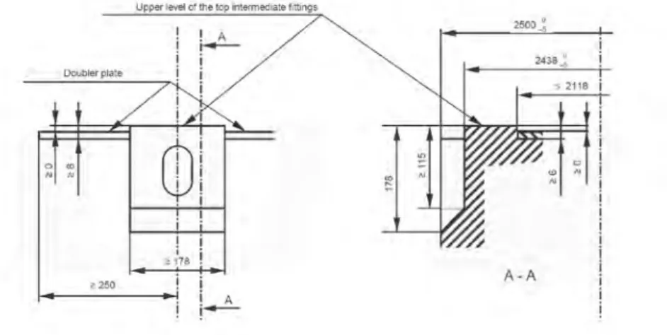
2.1.6.1 All classes of swap body may be stacked if the design permits it and has been subjected to appropriate tests. Such swap bodies will be fitted top fittings. The external faces will be 2.438 m (8 ft) when measured across the unit and 2.259 m between aperture centres.
Figure 3.58Swap body top fitting detail