An Environmental Critique of
In Situ Leach Mining :
The Case Against
Uranium Solution Mining
By Gavin Mudd
Victoria University of Technology
A Research Report for
Friends of the Earth (Fitzroy) with
The Australian Conservation Foundation
Preface
The mining and export of Australian uranium has been a controversial issue for many years, and will continue to remain an intense political issue for many more years to come. With a depressed world uranium market, the mining industry has been seeking to cut costs in order to make projects more economically viable. One such method of achieving this is a mining process known as In Situ Leaching (ISL) or Solution Mining. It involves pumping chemicals into the ground to dissolve the uranium mineral “in situ” and then pumping these uranium-laden solutions back to the surface for extraction and processing of the uranium into yellowcake for export.
It is claimed by the industry to be “a controllable, safe, and environmentally benign method of mining which can operate under strict environmental controls and which often has cost advantages”1. This ignores the reality of many former ISL trials and mine sites across Europe and North America, and the history of ISL trial mines in Australia. The technique of In Situ Leaching is not always controllable, safe, nor environmentally benign, and the hidden costs are usually borne by the underground environment. The process of ISL can lead to permanent contamination of groundwater, which is often used by local people and industries for drinking water supplies, and can also contaminate land which was otherwise good agriculturally productive land.
Australia is currently assessing two proposed uranium ISL mines in north-eastern South Australia, within the Lake Frome Basin. There are more deposits across Australia that would only be economic by using the ISL technique and are waiting further exploration or commercial commitment. In an attempt to document the truth of this technology and thereby influence the debate on ISL, Friends of the Earth (Fitzroy) (FoE) and the Australian Conservation Foundation (ACF) commissioned this report.
It covers the environmental importance of groundwater in the wider hydrologic cycle and the Australian environment, how the process of In Situ Leach mining works, potential technical, radiological and environmental problems that can arise, an extensive review of sites where ISL has been employed internationally, especially in the United States and Eastern Europe, and the trial experience with ISL in Australia.
The claims of the industry are then disputed and shown to be questionable. We hope this is a valuable contribution to the “debate”.
1In Situ Leach Mining of Uranium, Nuclear Issues Briefing Paper 40 - June 1997, Uranium Information
Contents
Preface
i
Summary
vi
1
Groundwater in the Environment
1
1.1 Groundwater Geology - Where is Groundwater Found ? 2 1.2 Groundwater Quality - Is The Water Suitable ? 5
1.3 Groundwater Recharge, Flow and Discharge 7
1.4 The Importance of Groundwater Across Australia 9
2
The Technique of In Situ Leach Mining
11
2.1 Overview 11
2.2 The In Situ Leaching Process 13
2.3 Underground ISL 19
2.4 Uranium Extraction 20
2.5 Waste Streams and Management 20
2.6 Radiological Aspects 21
2.7 Post-ISL Mining Restoration of Groundwater Quality 22
2.8 Mine Site Rehabilitation 24
3
Potential Problems of In Situ Leach Mining
25
3.1 Mechanical Failure 25
3.2 Chemical Interference Problems 27
3.3 Biological Problems 30
3.4 Poor Engineering Design 31
3.5 Human Error 35
3.6 Complex Geologic and Hydrogeologic Behaviour 35
4
American Experience with ISL
38
4.1 Overview 38
4.2 Regulatory Requirements 42
4.3 Wyoming and ISL 44
4.4 Wyoming Regulations 46
4.5 Texas and ISL 49
4.6 Texan Regulations 51
4.7 Other States 53
4.8 General Environmental Problems at the Early Sites 54 4.9 Environmental Problems at Early Wyoming Sites 54 4.10 Environmental Problems at Early Texan Sites 60 4.11 Decommissioning of ISL Uranium Production Facilities 68
5
International Experience with ISL
71
5.1 Bulgaria 71
5.2 Czech Republic 75
5.3 Germany 81
5.4 Commonwealth of Independent States 83
5.5 China 86
5.6 Pakistan 87
5.7 Turkey 89
5.8 Egypt 90
6
Australia’s Trial Experimentation with ISL
91
6.1 Overview of In Situ Leaching In Australia 91
6.2 The Current Context of ISL in Australia 92
6.3 The Honeymoon Story 98
6.4 The Beverley Story 106
6.5 Manyingee Uranium Deposit - History & Future ? 120
7
The Future of ISL ?
123
8
Acronyms
125
9
References
127
10
Glossary of Terms
139
11
Acknowledgements
141
Appendix One - Chemical Symbols & Elements
143
Tables
1 Estimates of the World Water Balance 2
2 Water Quality : Major Elements 6
3 Water Quality : Trace Elements 6
4 Water Quality : Radioactive Elements 7
5 Summary of ISL Uranium Sites to 1991 39
6 Average Leach Solution Composition - Minor Elements (mg/l) 40 7 Main Characteristics of US In Situ Leach Deposits 41
8 ISL Proposals, Trials and Mine Sites in Wyoming 45
9 ISL Proposals, Trials and Mine Sites in Texas 50
10 Maximum Values for Groundwater Protection 52
11 Miscellaneous ISL Trials 53
12 Baseline Groundwater Quality with Standard Deviation 56
13 Performance of Nine Mile Lake ISL Patterns 57
14 Leaching Phase Water Quality 58
15 Restoration Water Quality 58
16 ISL Mines and Decommissioning Financial Sureties 69 17 Estimated Decommissioning Costs for ISL Facilities 70
18 Typical Minor Lixiviant Components (mg/l) 73
19 Lixiviant Composition at Stráz Pod Ralskem (mg/l) 77 20 Radionuclide Content of Stráz Pod Ralskem Solutions 78 21 Typical Sulphuric Acid Leaching Solution Composition (mg/l) 83 22 Typical Carbonate Leaching Solution Composition (mg/l) 84
23 Effective Uranium Recovery in Batch Tests 87
24 Effective Uranium Recovery in Column Tests 87
25 Background Water Quality and Lixiviant Composition (mg/l) 88
26 ISL Timeline in Australia 93
27 ISL Uranium Deposits Across Australia 94
Figures
1 Schematic Representation of the Hydrologic Cycle 1
2 Braided River Environment 3
3 Examples of Groundwater Systems 4
4 The Importance of Groundwater Across Australia 10
5 Typical Roll Front Sedimentary Uranium Deposit 12
6 Typical ISL Bore Design and Construction 16
7 Overall Pressure Levels for Injection/Extraction in ISL 16 8 Typical 5-Spot and 7-Spot Injection/Extraction Well Patterns 17
9 Typical ISL 5-Spot Groundwater Flow Pattern 17
10 Full Scale Wellfield Flow Patterns 18
11 General Monitoring Well Configuration 19
12 The Underground ISL Technique 19
13 Injection/Extraction Pump Failure 26
14 Pipe or Distribution Pipe Failure 26
15 Evaporation/Retention Pond Failure 27
16 Groundwater Monitoring and Excursion Movement 31
17 Idealised View of Some Typical Faults 36
18 Utah Uranium Mine Tailings Seepage Plume Along Fractures 37
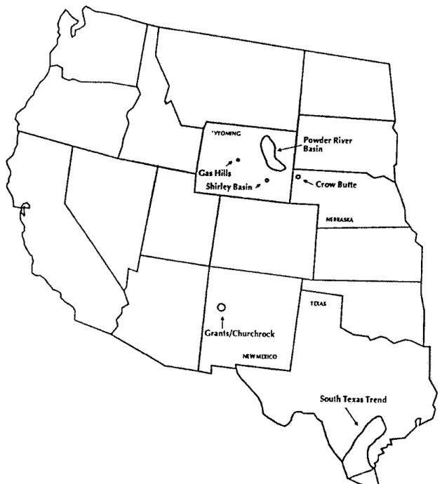
19 Location of ISL Sites in the USA 38
20 Map of Wyoming Uranium ISL Deposits and Projects 44
21 Bulgarian Uranium ISL Sites 72
22 Outline of the Stráz and Hamr Mines 75
23 Water Pressures at the Stráz and Hamr Mines 80
24 Block Leaching at Konigstein 82
25 Roll Front (ISL-type) Uranium Deposits in Australia 94
26 South Australian Uranium ISL Deposits 97
27 Location of the Honeymoon Uranium Project 99
28 Beverley Uranium Deposit Location 107
29 Regional Geological Cross Section 107
30 Outline of the Beverley Uranium Deposit 108
31 Regional Hydrogeology of Beverley 109
Summary - ISL Mines the World Over
In Situ Leach (ISL) or Solution Mining is a third alternative mining technique, quite different to conventional open cut or underground mining and milling operations. The ISL process can be applied to the extraction of uranium, copper, silver, gold, nickel and many other metals. For an ore deposit to be amenable to ISL it must occur within permeable materials, such as sands or sandstones, be saturated (ie - within an “aquifer” or groundwater system), and be confined above and below by low permeability materials (such as clays or shales). Given these general criteria, chemical leaching solutions are pumped into the ore deposit “In Situ” and dissolves the metal of interest. These metal-laden solutions are then pumped back to the surface and extracted in a processing plant. In this way, instead of the ore being excavated, crushed and chemically treated in a large surface processing plant, the process chemicals are injected underground into the ore directly. As such, the ISL technique generally has lower production costs than conventional mines. The ISL mining method has many advantages as well as inherent problems, and the success of this technique applied to the extraction of uranium is contained within this report and briefly summarised here.
The ISL Technique
The ISL technique, as described above, involves the drilling and operation of an extensive series of groundwater bores, injecting and extracting the chemical solutions continuously. There are two main options for the leaching chemistry - acid or alkaline solutions. In general, acid solutions (such as sulphuric acid) will extract a higher proportion of uranium and at faster rates than alkaline solutions (such as sodium or ammonia bicarbonate). However, acidic solutions will also mobilise high levels of environmentally sensitive and toxic heavy metals (such as cadmium, selenium, vanadium, lead, and others). The level of radionuclides, such as radium, mobilised from the ore into processing solutions tends to be higher in alkaline solutions.
The most critical part of the ISL process is to control the movement of the chemical solutions within the aquifer. Any escape of these solutions outside the ore zone is considered an excursion, and can lead to contamination of surrounding groundwater systems. Some of the most common causes of excursions, identified by international operations in the United States and across Europe, can be through old exploration holes that were not plugged adequately, plugging or blocking of the aquifer causing excess water pressure buildup and breaks in bores, and failures of injection/extraction pumps.
After the ore has been depleted and the maximum degree of uranium extraction achieved, it is good policy and (generally) a legal requirement to restore the water quality of the groundwater system that was mined to it’s pre-mining level. That is, remove all of the remaining chemicals from the aquifer and return the uranium and heavy metals to their original concentrations. In practice, this is extremely hard to achieve, especially with acidic solutions. Despite nearly 25 years of commercial ISL uranium mines in the United States (all using alkaline leaching solutions), regulators are yet to review or approve a report on the full scale restoration of groundwater at these sites, although they describe the restoration at earlier pilot sites as “satisfactory”.
With the current proposals at Beverley and Honeymoon in South Australia, and presumably for the new proposal at Manyingee in Western Australia, the restoration of groundwater is not planned nor is it being required by the regulators.
United States Experience
Texas has been the most prolific state for development of ISL uranium mines, with Wyoming also being popular for ISL sites. The first trial of ISL uranium mining was conducted at the Shirley Basin deposit by then Utah Construction & Mining Company2 in the early 1960’s with operation of an experimental full scale mine in the late 1960’s. It was shut down and converted to a traditional open cut mine. The uranium industry, keen to cut costs to compete with developing overseas uranium mines, nevertheless enthusiastically developed new ISL trials and by 1975, the first large scale commercial ISL uranium mine opened in Texas at Clay West. By 1992, there had a total of 62 sites where ISL had been applied, only 24 of which reached commercial production of uranium. Currently, due to the depressed nature of the world uranium market and higher costs at conventional mines, only 5 ISL uranium mines are operating in the USA, despite 12 being licensed.
The early ISL mines, such as Irigary Wyoming and Clay West/Burns in Texas, had many technical problems which led to poor operational and environmental performance. These included mineral precipitation of gypsum (CaSO4) and calcite (CaCO3) plugging
the aquifer, restricting groundwater flow and exacerbating excursions; complex reactions of chemicals with clays in the aquifer soils leading to permeability loss; excursions through old exploration boreholes; and excursions outside the mining zone. Problems were also noted with radiation levels, especially at some Texan ISL mines. The restoration of groundwater at many sites was not successful, and companies lobbied regulators to relax cleanup standards, and some sites still had significant problems even meeting these standards. The design of processing plants and infrastructure was also inadequate at some sites.
International Experience
The ISL mining technique has been enthusiastically employed at many uranium deposits across Eastern Europe and the Commonwealth of Independent States (CIS). However, the regulators and environmental policies of many of these countries was not, arguably, of a similar status as their United States counterparts. There is now a legacy of many contaminated sites and polluted groundwater across Bulgaria, the Czech Republic, the CIS and Germany, with some sites considered severe.
The majority of the ISL projects used sulphuric acid and the residual leaching solutions from ISL mines have migrated away from the mining zones. At some sites, notably in Bulgaria and the Czech Republic, these solutions have led to contamination of good quality groundwater systems that are used by nearby towns for their water supply or by local residents as their primary drinking water source. In some cases, the contaminated solutions have been demonstrated to reach these wells and valleys.
The chemical toxicity of these solutions, as well as their radiotoxicity, are a grave concern for modern regulators faced with the intractable cleanup problems now faced by the governments of the countries involved. At the Stráz site in the Czech Republic, the mined aquifer will never be able to be restored to it’s pre-mining water quality, and all restoration efforts are merely aimed at minimising contamination of surrounding groundwater. The cleanup of many sites is expected to take some decades, or even centuries.
Australia’s Trial of ISL
There has been two previous trials of ISL uranium extraction in Australia at Honeymoon, SA, in 1982 and at Manyingee, WA, in 1985. There are currently two trials operating, prior to Environmental Impact Statements being released or approved for Beverley, SA, and again at Honeymoon, SA, both starting in early 1998. The early trials, however, encountered significant operational and environmental problems which, combined with effective campaigning from the anti-nuclear movement across Australia, led to their refusal for further development.
The Honeymoon ISL trial in 1982 used sulphuric acid and iron sulphate leaching chemistry, and had problems with jarosite3 precipitating and plugging the flow of leaching solutions through the aquifer. The problems were completely unexpected and led to difficulties with performance of the trial. To date there has been no disclosure of the results and environmental problems of that trial by the companies involved or the SA government.
The ISL trial during 1985 at Manyingee, north-western WA, trialled sodium bicarbonate and hydrogen peroxide leaching solutions. It lasted for a total of 6 months and injected a total of 40.5 million litres into the ore zone aquifer. There was confusion about the trial project, especially with regards to the quantity of uranium produced, where it was stored, and operational and environmental performance of the trial.
3 - jarosite is a potassium-iron-sulphate mineral,
Both the Honeymoon and Manyingee trials were not required to restore groundwater following their respective ISL trials.
With the election of the Howard Coalition government to federal government in March 1996, the old projects of Beverley and Honeymoon were quick to re-apply for development. By late 1997 they had prepared and submitted plans for ISL trial mines, and these were approved by the SA government without hesitation or public scrutiny. These trials began operation in early 1998. Heathgate Resources, subsidiary of US giant nuclear multinational General Atomics and the company behind the current proposal for Beverley, released it’s EIS for an ISL mine on June 29. The new EIS for Honeymoon and extension deposits is expected towards the end of 1998.
Both of the current ISL trials at Beverley and Honeymoon have ignored the numerous potential problems found at ISL mines overseas, and especially at Honeymoon the problems of jarosite precipitation are not given any technical attention as to their cause or control. There can be significant problems expected during the operation of these trials.
The Manyingee deposit was bought by Paladin Resources in June 1998 and they immediately announced plans for an ISL mine within the next two to three years.
The Future of ISL ?
The technique of In Situ Leach uranium mining clearly entails many significant operational and environmental problems. However, as the nature of ISL mining is underground, and essentially “Out-of-sight and Out-of-mind”, these problems are ignored by the most toxic industry known to humanity. Successive state and federal Liberal governments appear to be blandly accepting company arguments over jobs at the expense of precious environmental assets and groundwater resources on the driest continent on the planet.
It is recommended that all current plans and operations be closed down until a full public assessment has been conducted and the restoration of groundwater proven to be successful.
The technique of In Situ Leaching is :
•
not controllable,
•
inherently unsafe,
•
unlikely to be able to meet “strict environmental controls”,
1 - Groundwater In The Environment
The hydrologic cycle is the term used to describe the perpetual movement of water between the oceans, the atmosphere and the land. Water is cycled between rainfall, rivers and lakes, soil moisture for use by vegetation and the ecosystem, the atmosphere, and storage deeper in subsurface materials. It is the storage of water in subsurface soils and rocks, known as aquifers or groundwater basins, and their slow release to surface water systems, that maintains baseflow in rivers between rainfall events (Dillon, 1995).
Figure 1 - Schematic Representation of the Hydrologic Cycle (Freeze & Cherry, 1979)
If one was to determine the total volumes of water involved in each part of the environment, it would be found that second to the oceans and seas of the world, groundwater is the second most abundant source of water with approximately 4% of the world’s water being found underground (Freeze & Cherry, 1979). Groundwater can therefore be considered an important, perhaps critical, part of the hydrologic cycle. It is simply that part of the underground or geologic environment where water can be found, typically in porous rocks that allow for the storage and flow of fluids such as sandstones. Despite the volumetric superiority of groundwater to surface waters, the residence times are substantially different. The residence time for water in a river channel is of the order of weeks, whereas for some groundwater systems it can be of the order of 10’s or 1,000’s of years. The Great Artesian Basin (GAB), one of the world’s largest and oldest groundwater systems covering 1.7x10⁶ km2 of Queensland, New South Wales and parts of South Australia and the Northern Territory, has residence times estimated to be greater than 1,000,000 years (Habermehl, 1980; Bentley et al.; 1986, Torgersen et al., 1991).
Table 1 - Estimates of the World Water Balance (Freeze & Cherry, 1979) Surface Area 106 km2 Volume 106 km3 Volume % Equivalent Depth m* Residence Time Oceans and Seas 361 1370 94 2500 ~ 4,000 years Lakes and Reservoirs 1.55 0.13 <0.01 0.25 ~ 10 years Swamps <0.1 <0.01 <0.01 0.007 1 - 10 years River Channels <0.1 <0.01 <0.01 0.003 ~ 2 weeks Soil Moisture 130 0.07 <0.01 0.13 2 weeks - 1 year
Groundwater 130 60 4 120 2 weeks - >10,000 years Icecaps and Glaciers 17.8 30 2 60 10 - 1,000 years
Atmospheric Water 504 0.01 <0.01 0.025 ~ 10 days Biospheric Water <0.1 <0.01 <0.01 0.001 ~ 1 week * Assuming uniform distribution across the entire surface of the earth.
This stark difference in residence times leads to the necessary conclusion that if the ecological integrity of a groundwater system is not maintained, it may take a considerable amount of time to re-establish.
Initial studies of groundwater earlier in this century focused on the potential water yield of a system, and more recent years has seen increasing concern over contamination and groundwater quality (Fetter, 1993). However, it is only in the past decade that the myriad of complex environmental functions that groundwater performs have been recognised.
Groundwater provides a source of drinking water for many parts of the world, with groundwater in the United States providing over 40% of public water supplies (Fetter, 1993). In addition to providing a source of water, groundwater performs many important ecological functions. These include discharge to streams and rivers to maintain baseflows, discharge to springs and interaction with other surface water systems. If the groundwater becomes contaminated, this could persist for the residence time of the groundwater system, creating a significant risk to the functioning of ecological systems, a problem widely recognised in Melbourne’s western suburbs (CSIRO, 1996).
1.1
Groundwater Geology - Where is Groundwater Found ?
The nature and location of groundwater is controlled by the formation and structure of the geology of a region. This can be related to sedimentary materials such as sands and gravels, or various rock types such as sandstones or fractured limestones and granites. As such, groundwater can be found almost wherever one cares to look - it is merely a question of how deep one must drill. However, the flow of groundwater from that system may not be sufficient to yield useful quantities of water.
In many cases the pressure of water within a groundwater basin will allow it to flow above the ground surface if a bore or well is drilled into the aquifer. This is known as artesian pressure, and is related to a layer of clay or lower permeability1 material (known as an aquitard) confining the water to that aquifer and thereby leading to a higher water pressure.
Sedimentary Groundwater Systems
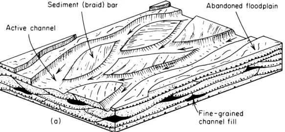
Groundwater is commonly found in the materials laid down by river channels and floodplains. This includes gravel, sand, silt or clays. A layer of sand might be deposited under a particular environment, and over time water accumulates forming an aquifer or groundwater reservoir. They are known as alluvial deposits or aquifers, and due to the inherent complexity of shifting river channels and ever-changing flow velocities, the exact layering and connection of sands or clays can be difficult to determine, even with an extensive number of boreholes. Two distinct types of alluvial deposits are recognised - braided river and floodplain alluvial deposits (Freeze & Cherry, 1979).
Braided river environments generally occur in settings where the sediment available for transport has considerable coarse-grained sand or gravel and where river velocities are large due to steep regional topography. Sequences of sands and gravels can develop, with only minor zones of silty or clayey sediments. The flow of groundwater through an old braided river bed can often thus be unpredictable due to complex channels and bars (braids) that are formed during deposition.
Figure 2 - Braided River Environment (Freeze & Cherry, 1979)
Floodplain river environments also contain coarse-grained deposits of sands and gravels, but are typically dominated by fine-grained silty or clayey deposits. They are characterised by lower slopes and smaller flow velocities. The complex channels that are formed are also highly variable and very difficult to characterise with borehole data.
1permeability - the rate at which groundwater can flow through a particular material (typically expressed
Other types of sedimentary type groundwater systems are formed by the action of winds (aeolian deposits) or glaciers. They are also highly variable, and are characterised by fractures and variable properties. Fractures, or lines where the sediments are discontinuous, often provide avenues for groundwater flow to escape.
Rock-Based Groundwater Systems
Groundwater can also be found in many types of porous or fractured rocks, such as sandstone, limestone or even granite and basalt. The rocks are often part of large regional geological systems. The flow of groundwater is therefore controlled almost entirely by regional geological and structural features. Fractured rock aquifers generally contain much lower quantities of groundwater, and are highly variable in their flow properties and quality.
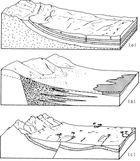
Figure 3 - Examples of Groundwater Systems (Freeze & Cherry, 1979)
(a) gently dipping sandstone aquifers with outcrop (recharge) area along mountain foot; (b) interfingering sand and gravel aquifers extending from uplands in intermountain region; & (c) faulted and folded aquifer in a desert region. Surface water bodies reflect structural features,
1.2
Groundwater Quality - Is The Water Suitable ?
The chemical and biological components or quality of groundwater determine it’s suitability for particular uses, such as potable drinking water, agriculture or environmental effects. As water moves through soils and rocks it can dissolve some minerals. The exact concentration of different components in groundwater will depend on the type of soils and rocks the water has passed through and sometimes the microbiological action. In the same way that water can dissolve minerals, minerals can also be precipitated again as a solid. Understanding the chemical controls on groundwater can thus be a very important step in locating ore deposits, or the movement of a plume of contamination through an aquifer.
There are a number of terms used to describe and quantify the quality of water :
Total Dissolved Solids (TDS) - the total mass of dissolved elements per litre of a water sample, often referred to as salinity.
Concentration - the mass of an element dissolved in water, units are usually mg/l (milligrams per litre, 10-3g/l) or µg/l (micro grams per litre, 10-6g/l).
pH - a measure of the acidic (H+) or alkaline (OH-) tendency of a water sample. At 25º C, a pH of 7 is neutral, less than 7 acidic and more than 7 alkaline.
Mineral - a compound of different elements. Examples include calcite (CaCO3),
jarosite (KFe3(SO4) 3.9H2O), pyrite (FeS2) or halite (NaCl).
Redox Potential - or oxidation/reduction potential (Eh), is a measure of the chemical energy in a water sample, relative to a known standard, measured in mV (millivolts, 10-3V). A positive redox value, known as oxidising, is typical of the presence of oxygen, and a negative value, known as reducing, usually means the absence of oxygen.
Solubility - the amount of a mineral to dissolve in a given amount of water. Saturation - the maximum concentration of a mineral for a given water chemistry and temperature.
The dissolved components of water can be single elements such as calcium (Ca) or chloride (Cl), or compounds such as carbonate (CO3) or sulphate (SO4). The levels of
these different elements and compounds will determine it’s quality and potential use. Due to different abundances of elements in soils and rocks, the water chemistry will be dominated by the group of common elements - sodium, calcium, potassium, magnesium, chloride, sulphate, carbonate. Minor amounts of aluminium and iron may also be present. Trace quantities of other elements such as selenium, arsenic, barium, or molybdenum can be also be found, but generally in significantly lower concentrations.
Different minerals also vary in the degree to which they will dissolve in water, known as solubility. At some point, no more of a particular mineral will dissolve as the water is saturated with respect to that mineral, in much the same way a cup of water will only dissolve a certain quantity of sugar. It is also possible that if a water becomes over-saturated with a mineral, then the excess amount of that mineral will precipitate out of solution as a solid until the water chemistry reaches a new equilibrium.
The solubility of a particular mineral will also depend on the pH and redox state of the water. For highly acidic conditions (pH less than 7), many trace and heavy metals are highly soluble, whereas under highly alkaline conditions (pH greater than 7) many trace and heavy metals are immobile and stay in a solid form. The solubility also depends on the redox state of the water. In the same way as different minerals are soluble under different pH conditions, many minerals are insoluble under negative (or reducing) redox conditions and highly soluble under positive (or oxidising) redox conditions.
A sample of good fresh water will have quite low concentrations of dissolved components, while seawater has quite high concentrations and is referred to as highly saline. There are established national and international levels for different components, including radioactive elements, for different uses of water, with some typical guideline values shown below in Tables 2 to 4 (although some parameters do vary significantly). The values for drinking water are based on either a health or environmental toxicity risk approach or simply taste and odour.
Table 2 - Water Quality : Major Elements (ANZECC, 1992)
TDS pH Na Fe Cl SO4 NO3 F Cu Zn mg/l - mg/l mg/l mg/l mg/l mg/l mg/l mg/l mg/l Drinking Water 500 -1,000 6.5 -8.5 300 0.3 400 400 10 - 1 5 Irrigation 4.5 -9.0 - 1 30 -700 - - 1 0.2 2 Livestock 1 2,000 -13,000 - - - - 1,000 30 2 0.5 20
1 - Depending on livestock type, such as sheep, beef or dairy cattle.
Table 3 - Water Quality : Trace Elements (ANZECC, 1992)
Al As Ba B Cd Cr Pb Hg Mn Mo Se V mg/l µg/l mg/ l mg/l µg/l µg/l µg/l µg/l mg/l µg/l µg/l µg/l Drinking Water 0.2 50 1 1 5 50 50 1 0.1 - 10 -Irrigation 5 100 - 0.5 - 6 10 1,000 200 2 2 10 20 100 Livestock 5 500 - 5 10 1,000 100 2 - 10 20 100
Table 4 - Water Quality : Radioactive Elements (Fetter, 1993) Ra-226 Ra-228 Rn-222 U Gross-α Gross-β
(pCi/l) (pCi/l) (pCi/l) (µg/l) (pCi/l) mrem ede1/yr
Drinking Water 20 20 300 20 15 2 4
Irrigation 3 - - - - 0.1 (Bq/l) 0.1 (Bq/l)
Livestock 3 - - - 200 -
-1
- ede is effective dose equivalent.
2
- excluding radium-226, radon-222 and uranium. 3 - ANZECC, 1992.
Thus the quality of water, either found naturally in the environment or treated for human use, is highly variable.
1.3
Groundwater Recharge, Flow and Discharge
Groundwater will flow through rocks due to differences in water pressure. This is often related to the height of the geology the groundwater is found within, but it does lead to the questions of where water enters a groundwater system and how (the recharge area), the time it might take to flow from one point to another (the flow path), and where does the water eventually discharge from groundwater back to the surface environment (the discharge area). The overall quantities of recharge and discharge should be similar if a groundwater system is in equilibrium or balance. Excessive discharge (such as too many bores) over recharge can lead to a significant long term degradation of a groundwater system.
Groundwater Recharge
Recharge to a groundwater system, the process whereby rainfall migrates through surface soils and replenishes the water supply of a groundwater system, is often a technically difficult process to qualify and quantify.
The main ways that recharge can be studied include the use of computer modelling of groundwater systems, detailed field sampling and monitoring of the recharge area over long periods of time (dependent on the size and nature of the groundwater system), the use of groundwater chemistry to elucidate the mixing of different waters (including the use of specific elements, isotopes and radionuclides such as tritium), and studies of the geological properties of the aquifer rocks where they outcrop in the recharge area (refer to Figure 3).
Recharge can often be due to single events in space and time, such as during the last glacial period, leading to the problem of determining long term average recharge processes (Freeze & Cherry, 1979). The proportion of rainfall that might enter or recharge a groundwater system ranges markedly, with some values less than a few percent, or expressed as several millimetres (Mazor, 1997).
Groundwater Flow
The direction groundwater will flow is dependent on the water pressure within the aquifer, which will be closely related to geological structure. The main methods use to determine the dominant direction of groundwater flow is to drill a series of groundwater bores to monitor the overall trends in water pressures, and then using these to analyse overall flow rates and directions.
The overall water pressures within an aquifer are contoured and plotted on a map (known as the piezometric surface), with groundwater flowing perpendicular to the pressure contours. The rate of groundwater flow will depend on the permeability of the aquifer materials, such as sandstone or silty gravels. A variety of tests can be conducted to determine an aquifer’s permeability, either from retrieved drill core samples or via pumping tests of the aquifer itself.
The volumetric flow rate will also depend on the thickness of the aquifer, as some aquifers are only several metres thick but parts of the Great Artesian Basin aquifers are hundreds of metres thick and can thus transmit large quantities of groundwater for the same permeability and pressures.
Groundwater will typically flow from the higher recharge areas to the lower discharge areas. With the advent of fast computers, mathematical models are now widely used to help in quantifying the flow of groundwater systems to aid in good management. However, like many numerical computer models, the quality of results obtained from such a study are entirely dependent on the quality of the input data on basic and fundamental hydrogeologic processes for the particular system being modelled.
Groundwater Discharge
After a certain length of time underground, groundwater will eventually find it’s way to a discharge zone - the area where the water will move into a different part of the hydrologic cycle. Common discharge areas for groundwater include lakes and rivers, surface springs, or into another regional groundwater system (related to geology).
The recharge of near-surface aquifers or the water table is one of the most important groundwater processes in sustaining the baseflow of many rivers in between rainfall events, which is in fact the most common discharge area for water table aquifers.
The rate of discharge will depend on pressure levels and flow characteristics of the aquifer, and can vary from small to much larger volumes of millions of litres per day. Any change in the water pressures of a groundwater system (such as that due to bores) in the vicinity of a discharge area, can therefore have a significant impact on the quantity of groundwater discharge.
Miscellaneous Influences on Groundwater Flow
There are many processes that can complicate the interpretation of a groundwater flow system. These can include the presence of permeable or impermeable faults, highly variable geology, complex chemical interactions, bacterial influences, and subsidence problems (that is, settlement of the ground surface due to lower groundwater pressures) among others. These can lead to modification of the physical properties of an aquifer, causing a reduction in flow rates, a decrease in groundwater quality, or a change in the overall flow regime due to a fault allowing discharge from one groundwater system into a different system. Many of these factors, although recognised, are often very hard to predict the exact behaviour of, due to their complex nature, without extensive field studies and research. However, if the integrity of a groundwater system is to be maintained, these issues are of the utmost importance.
1.4
The Importance of Groundwater Across Australia
The majority of the Australian population lives on the east coast where there is generally good access to high volumes of good quality water from forested catchments. Only select cities actually use an appreciable proportion of groundwater to augment their potable water supplies, such as Geelong, Newcastle and Adelaide (about 30% of 30 billion litres, 20% of 100 billion litres and 5% of 150 billion litres respectively) (AWRC, 1992). Darwin draws about 10% of their potable water supply of 25 billion litres from groundwater (AWRC, 1992). Perth, however, draws upon approximately 65% of it’s potable water supply of 250 billion litres from groundwater (AWRC, 1992). In perspective, groundwater contributes over 90% of the water supply for about half of the area of the Australian continent (Dillon, 1995).
For most parts of the arid interior of Australia, groundwater is often critical. In total, approximately 460,000 people in Western Australia, 45,000 people in South Australia, 50,000 people in the Northern Territory, 100,000 people in New South Wales, 220,000 people in Queensland and 60,000 people in Victoria are served by water supplies derived from groundwater (AWRC, 1992) (refer to Figure 4). This represents about 120 communities in Western Australia, 85 communities in South Australia, 55 communities in the Northern Territory, 165 communities in New South Wales, 200 communities in Queensland and 65 communities in Victoria (AWRC, 1992) (refer to Figure 4).
For much of the groundwater systems within the arid interior, the reserves are fossil water, or groundwater which was recharged in past geological eras that were much wetter than the current era (Jacobson & Lau, 1983). Thus there is significant potential for effectively mining a groundwater system at an unsustainable rate since there is no reasonable process for recharge. Much of the arid interior has only been able to develop important economic industries, such as pastoralism, due to the presence and use of such ancient groundwater systems (Jacobson & Lau, 1983).
2 - The Technique of In Situ Leaching
2.1
Overview
The process of In Situ Leaching (ISL) combines both the mining and beneficiation of a particular mineral or element in one step. It can be used for the recovery of uranium, copper, nickel, gold, iron, phosphate, salt and also potash, although uranium and copper are the principal elements currently mined with ISL. Typical mining involves two main steps of digging or extracting the ore with an underground or open cut mine and then processing the ore with a chemical mill to leach the element of interest from the bulk of the ore. In Situ Leaching involves directly circulating the chemical leaching solutions (typically used in the mill) through the ore zone in the ground and recovering the solutions to extract the uranium, copper or element of interest. In this method, no excavation of ore is required and it reduces the handling of large volumes of ore materials and no traditional tailings dam is therefore required.
However, not all deposits are suitable for application of the ISL technique. In order for ISL to work, the following criteria are generally applied to the ore body (Montgomery, 1987; Underhill, 1992; Brunt, 1998) :
• must occur in porous and permeable rocks (usually a sand or sandstone);
• confined (isolated) above and below by continuous impermeable strata such as clays or shales;
• must be located below the water table and therefore saturated with the naturally occurring groundwater;
• the water pressure must be artesian relative to the clay confining layer above (a minimum of about 15 metres is preferred, 75 m or more is desirable);
• must have uranium mineralisation which is in a form that can be readily leached, eg coffinite or uraninite;
• must meet minimum grade and thickness criteria necessary for economic recovery of the contained uranium;
• effective contact between the leach solution and uranium minerals.
The deposits that typically meet these criteria are usually found in sandstones or in the sands of palaeochannels (old river beds). The uranium is dissolved from an area of primary mineralisation (ie - the original source rocks that contain uranium) and transported through flowing groundwater. In order to dissolve the uranium, the water must be oxidising. When the water reaches a part of the aquifer that is reducing, the uranium precipitates out of solution to form insoluble minerals such as coffinite (USiO4)
or uraninite (UO2). The deposition of uranium occurs on the surface of sand grains as
the oxidising groundwater flows through the reducing part of the aquifer, progressively enriching the deposit. Such deposits are known as “roll front” or “geochemical cell” type ores, and are typically long and narrow and tens of metres thick (Langmuir, 1997).
Figure 5 - Typical Roll Front Sedimentary Uranium Deposit (Langmuir, 1997)
Schematic cross-section of an idealised uranium roll-front orebody showing the zonation of elements and primary hydrologic and geochemical features. Oxidised groundwaters flow from left to right. The roll front and associated redox interface moves in the same direction.
There can also be other minerals and elements associated with the uranium mineralisation including pyrite (FeS2) and carbonaceous matter (either organic or as
carbonate, CO3). The extraneous minerals like pyrite and organic matter are often
referred to as gangue minerals (Kasper et al., 1979). Trace elements can include arsenic, vanadium, zinc, selenium, molybdenum, usually present as sulphide minerals (such as zinc sulphide, ZnS). The exact proportions of pyrite, carbonate and other impurities will determine the suitability of different leaching chemistries.
2.2
The In Situ Leaching Process
The ISL process involves the drilling of a series of wells into the aquifer containing the deposits. A concentrated leaching solution, called the lixiviant, is then pumped into the aquifer to oxidise and dissolve the uranium minerals, so they can be pumped back to the surface for extraction at a processing plant. The solution before entering the ore deposit is called barren lixiviant since it contains no dissolved uranium or the mineral or element being extracted. After moving through the ore, it is known as pregnant lixiviant since it is concentrated in the element of interest. The wells are divided into injection and extraction wells, and a number of extra wells are located outside the area where active pumping occurs to monitor any escape of the mining solutions. Due to the inherent complexity and variability of roll front type uranium deposits, there are a variety of leaching solutions that can be used to dissolve the uranium, as well as numerous configurations for pumping and monitoring wells.
Choosing the Leaching Solutions & Chemistry
Uranium is soluble under both acidic and alkaline conditions, but insoluble under reduced conditions. Thus it possible to use either acidic or alkaline leaching chemistry. Typical acids that have been used are sulphuric (H2SO4) or nitric (HNO3) acid; and
ammonia bicarbonate (NH4HCO3), sodium bicarbonate (NaHCO3) or carbon dioxide
(CO2) for alkaline leaching chemistry (Tweeton & Peterson, 1981). An oxidising agent
must also be introduced to ensure the solutions stay in a positive redox state, which could include hydrogen peroxide (H2O2), oxygen (O2) or sodium chlorate (NaClO3)
(Tweeton & Peterson, 1981). The process of ISL can extract up to 60-80% of the uranium from a roll front type ore deposit (Brunt, 1998).
The main factors that determine the choice of leaching chemistry are (Kasper et al., 1979; Tweeton & Peterson, 1981) :
• potential or desired rates of dissolution or the rate at which the uranium enters solution;
• effects of leaching solutions on aquifer formation properties (such as aquifer permeability reduction);
• the cost of chemicals;
• the chemical reactions between leaching solutions and gangue minerals;
• the requirement (and ability) to restore groundwater quality to pre-mining levels after the completion of ISL pre-mining.
The latter two of the above are perhaps the most important aspects in the choice of leaching chemistry. Acid leaching was trialled in the USA in the late 60s through to the early 80s, and has been used extensively in Europe and the CIS. New ISL projects in China, Mongolia and Kazakhstan are also using or planning to use sulphuric acid ISL chemistry. Currently in the USA, all ISL uranium production is with alkaline leaching chemistry using carbon dioxide or sodium-carbonate and oxygen (USDoE, 1995). The ability of acid versus alkaline leaching solutions to meet these above criteria is critical in understanding the environmental impacts likely for each method.
Acid Leaching Chemistry
The most common acid used in ISL is sulphuric acid (H2SO4), one of the cheapest
chemicals available (Tweeton & Peterson, 1981). Other acids are technically possible, such as hydrochloric (HCl) or nitric acid (HNO3), but sulphuric acid remains the most
common as the costs of alternatives are prohibitive (Kasper et al., 1979). The various oxidising agents used include sodium chlorate (NaClO3), oxygen, manganese
dioxide(MnO2), ferric sulphate (FeSO4) and oxygen (Kasper et al., 1979). There have
been trials of acid leaching at sites in Texas and Wyoming in the USA, and commercial operation at sites in Bulgaria, Germany, the Czech Republic.
It has been found that pH must be kept below 2 for optimum leaching rates, above 4 the uranium will not dissolve and recovery is therefore not possible (Kasper et al., 1979). As well as uranium, the solubility of many trace and heavy metals is also greatly increased, and the concentration of arsenic, selenium, lead, vanadium and other elements can be several orders of magnitude higher than pre-mining levels. These can interfere with the extraction process
Alkaline Leaching Chemistry
The various alkaline leaching agents that can be used include carbon dioxide (CO2),
sodium carbonate-sodium bicarbonate (Na2CO3-NaHCO3), ammonium
carbonate-bicarbonate ((NH4) 2CO3-NH4HCO3). The most common oxidising agents are hydrogen
peroxide and oxygen. Many trace and heavy metals are insoluble under alkaline conditions, and the level of impurities in alkaline mining solutions are much lower. Comparing Acid and Alkaline Lixiviants
Generally, it has been found that alkaline lixiviants give slower leaching rates than acidic lixiviants, and do not leach a very high proportion of the uranium (Kasper et al., 1979). Kasper et al. (1979) and Tweeton & Peterson (1981) present the following points of comparison :
Advantages •significantly lower levels of impurities; of
Alkaline
•relatively noncorrosive solutions which have a lower probability for mechanical failure and subsequent spills;
•higher efficiency of regenerating and recycling leaching solutions due to less impurity problems, resulting in smaller waste stream flow rates;
•minimal precipitation of calcium minerals in the extraction process (calcite, CaCO3, gypsum, CaSO4).
Advantages •leaching rates are more rapid, thereby reducing the mining period; of •uranium recovery rates are higher;
Acid •lower potential for dissolving radium-226;
•no interference problems with clays (compared to sodium or ammonia based solutions).
Controlling the Movement of Leaching Solutions
One of the most critical operational principles of any In Situ Leach mine is to control the movement of leaching solutions within the groundwater area being mined. Not only is it important from an economic standpoint (the solutions contain the product), but it is of the utmost importance for environmental management as the groundwater surrounding the mine site can often be used by local farmers, nearby towns as drinking water or discharge to other sensitive parts of the environment. An escape of leaching solutions is known as an excursion.
The main techniques used to achieve this are the careful design of groundwater bores to prevent leakage via the bore, and always pumping out more water than the quantity of solutions injected.
Groundwater Bore Design
Each groundwater bore that is drilled into the deposit is a possible avenue for the escape of solutions if it does not remain sealed and isolated to groundwater of that zone only. A typical bore would be designed and constructed so that the bore is built with a strong casing (such as PVC plastic). The PVC would only be perforated (slots cut into the casing to allow the inflow of water) in the zone of mining, with sand or gravel placed around this part of casing. The remainder of the casing is backfilled with clay, such as bentonite, to act as an impermeable barrier to vertical flow. A typical example is shown in Figure 6.
Adjusting Injection and Extraction Rates
The flow of groundwater is determined by differences in water pressure. Thus, if the injection of solutions were to lead to excessive pressures in the mining zone, this increases the chances of those solutions escaping since the pressure gradients would be away from the injection/extraction well system. To overcome this, ISL mines always extract more water than they inject. This tries to ensure that there is an overall decrease of pressure in the local area of injection and extraction and water will always flow towards the extraction well. The amount of this excess extraction generally ranges between 0.5 to 5% of the water injected. This extra water is known as the bleed solution. This is represented in Figure 7.
Figure 6 - Typical ISL Bore Design and Construction (Brunt, 1998)
Figure 7 - Overall Pressure Levels for Injection/Extraction in ISL
Configuration of Injection/Extraction Wells
The configuration of injection and extraction wells is also quite important for the successful control of the mining solutions. The most common pattern of wells is known as the 5-spot pattern, although 7-spot and even 13-spot patterns have also been used (Kasper et al., 1979). The main principle behind the patterns is that four (or six or twelve) injection wells surround one extraction well. A 5-spot pattern is thus square shaped, while a 7-spot pattern is hexagonal shaped.
Figure 8 - Typical 5-Spot and 7-Spot Injection/Extraction Well Patterns (USEPA, 1995)
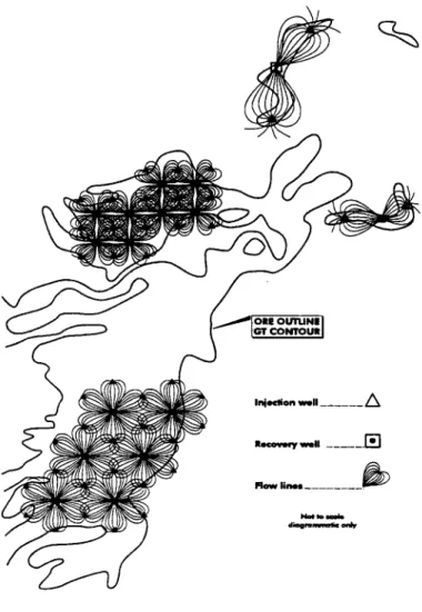
The different patterns are normally arranged in sequence to overlap, forming a line of injection and extraction wells, known as drives. This helps to optimise the ratio of injection and extraction wells required to cover an orebody. This leads to a series of wells that cover an area of several hectares at any one time in a commercial scale ISL mine, and hence is known as the wellfield. The spot pattern used not only depends on the physical and chemical characteristics of the aquifer and orebody, but the type of pattern used will determine the density or number of wells covering a certain area, which largely influences the costs of restoration (USDoE, 1995). An example is shown below, which includes the overall flow patterns for groundwater and solutions.
Figure 10 - Full Scale Wellfield Flow Patterns (Brunt, 1998)
Monitoring Outside the Mining Zone
It is of the utmost importance for any In Situ Leach mining operation to install a well designed groundwater monitoring system that can detect if any escape of solutions occurs (excursion). Groundwater monitoring bores are drilled into the same aquifer outside the mining zone, and also into aquifers above and below the mining zone (if aquifers are present). It is intended that the wells are closely spaced so that any excursion of lixiviant will be intercepted by a monitoring well, detected by routine sampling and remedial action can be planned and undertaken. A typical monitoring well configuration is shown in Figure 10 below, although the exact layout will depend on the hydrogeological nature of the orebody aquifer.
The frequency of monitoring is often at least daily or weekly for indicator parameters, such as sulphate or electrical conductivity (directly related to total salinity), and fortnightly for a complete analysis of groundwater quality parameters. Recent advances in electronic monitoring technology, that can be placed inside a bore permanently and monitor pH, salinity or a specific element of interest, allow for continuous data collection and more rapid detection of any excursions.
Figure 11 - General Monitoring Well Configuration (Kasper et al., 1979)
2.3
Underground ISL
At many sites across Eastern Europe, the process of In Situ Leaching has been within the confines of an underground mine. This is generally achieved through the use of underground mining stopes being leached with the preferred reagents, with the enriched solutions collected at the bottom of a stope and pumped to the surface for processing. It is often used to extend the life of an underground when only the lower grades of an ore remain, grades which would otherwise be uneconomic to mine otherwise. This technique was quite popular in Eastern Europe, particularly Bulgaria and Germany.
2.4
Uranium Extraction
After the pregnant lixiviant is extracted from the ore zone, it is pumped to the processing plant. Here the uranium is extracted from the solutions using standard metallurgical techniques. There are typically two main choices for this process - solvent extraction or ion exchange. Each of these represents different technical advantages and problems for specific deposits, although only a brief review is required for the context of this report. The solutions are generally cycled through the wellfield, orebody and processing plant numerous times before being replaced by fresh lixiviant (due to the buildup of contaminants which interfere with the extraction process or lead to impurities in the final product).
Solvent Extraction
The principle behind solvent extraction is that uranium is highly soluble in an organic solvent compared to water. By mixing different organic solvents (such as kerosene, alkyl phosphates and amines) with the recovered lixiviants, the uranium is concentrated in the organic fraction, which can then be easily removed to extract the uranium separately as yellowcake.
Ion Exchange
Ion exchange works on the principle that selected elements or compounds can be progressively concentrated on the surface of solid resins, known as ion exchange resins. The pregnant lixiviant is pumped through an ion exchange column, and the uranium concentrated on the resin. After the resin becomes saturated, the process is reversed and the column flushed to extract the uranium for refining to yellowcake.
2.5
Waste Streams and Management
The process of In Situ Leaching leads to the formation of many liquid and solid waste streams. These are produced from the bleed solutions, waste processing solutions, solid residues that build up due to the precipitation of minerals from the highly concentrated solutions involved, solid waste from the processing plant (such as contaminated clothing and equipment), and other normal wastes from industrial facilities.
Due to the nature of In Situ Leach mining, quite large volumes of waste waters are created, which are often highly saline and contain toxic levels of heavy metals, process chemicals and radionuclides. The bleed solution (the excess water pumped out over that injected) is often the most significant component. For ISL mines operated at 25 litres per second (a relatively small scale), the quantity of water pumped each day would be 2,160,000 litres, which for a 2-5% bleed solution would form 43,200 to 108,000 litres per day to dispose of (or 15,768,000 to 39,420,000 litres per year; 15.8 Ml to 39.4 Ml). Some ISL mines operate at flow rates of greater than 100 litres per second, and thus the quantities of water involved are proportionally higher.
Waste solutions are also generated by the processing plant. Fresh lixiviant needs to be introduced regularly to ensure optimal efficiency in the processing plant, and the discarded solutions (now called raffinate) are disposed of.
The different waste water streams are temporarily stored in a retention pond. The final disposal method can be either re-injection into the same aquifer, re-injection into a deeper aquifer that is unused and does not interact with other aquifers that are currently used, or evaporation of the water to leave a solid residue that can be disposed of in an engineered facility designed to minimise leakage of contaminants.
Solid wastes are generally disposed of at an approved radioactive waste management site, or in an engineered facility on site.
Since the orebody itself is not extracted, there is no tailings or residual rock material remaining in a large tailings dam.
2.6
Radiological Aspects
The mining of uranium ores leads to the presence of radiation. This can be in the form of alpha, beta and gamma-emitting radionuclides formed from the uranium decay sequence.
The principle radioactive elements released during In Situ Leach uranium mining are uranium, thorium, radium, radon, and their respective progeny (Tweeton et al., 1982; Kasper et al., 1979). Acidic leaching chemistry tends to mobilise a small proportion of the radium from the orebody, while alkaline leaching mobilises higher quantities since radium hydroxide is more soluble than radium sulphate (Kasper et al., 1979). However, acid leaching does mobilise significant concentrations of thorium (Tweeton et al., 1982) The decay of radium and thorium leads to the formation of highly radioactive radon gas, which is the main source of workers’ radiation exposure for uranium mining operations. The radium and radon are transported in the mining and processing solutions to the surface. When at the surface and the solutions are pumped to the retention pond, appreciable quantities of radon can thereby be released (Kasper et al., 1979). The radon gas can be transported in the direction of prevailing winds significant distances away from the mine, where radon will decay to a stable solid due to it’s very short half-life. Another source of radiation is uranium dust and residues that buildup around the processing plant (such as salts that precipitate or evaporate and precipitate from the highly concentrated solutions). The venting of air from the processing plant can lead to the release of uranium dust into the wider environment (Kasper et al., 1979).
2.7
Post-ISL Mining Restoration of Groundwater Quality
After the orebody has been mined, it is good policy and practice to restore the groundwater quality to it’s pre-mining levels. It is required by all state and federal regulators in the United States. This involves the chemical treatment of the affected area to remove the residual solutions and chemicals from the mined out area and immobilising any elements that have been dissolved into solution by the ISL process, such as arsenic and other trace elements. The restoration of an aquifer following In Situ Leaching is done in four phases (Schmidt, 1987; Catchpole, 1995; USDoE, 1995) :
Phase One - Pumping of contaminated water :
the injection of the leaching solution is stopped and the remaining contaminated liquid is pumped from the mined area. Subsequently, clean groundwater flows in from outside of the leaching zone;
Phase Two - Pumping and pre-treatment :
pumping with treatment of the pumped liquid (by reverse osmosis) and re-injection into the former leaching zone. This scheme results in circulation of the pre-treated liquid;
Phase Three - Chemical remediation :
with the addition of a reducing chemical (for example hydrogen sulphide H2S or sodium sulphide Na2S). This causes the precipitation and thus
immobilisation of most contaminants; Phase Four - Final pumping :
circulation of the liquid by pumping and re-injection, to obtain uniform conditions in the whole former leaching zone.
The most critical part of any restoration attempt is the standards or quality that the groundwater is being restored to. It is extremely important to have an extensive data set of background (pre-mining) groundwater quality before ISL mining, to allow the determination of restoration standards for all quality indicators, such as sulphate, pH, total salinity, uranium, radium, arsenic, molybdenum and selenium among others.
The total volume of water that needs to pumped and the length of any restoration attempt is dependent upon the complex chemistry of the specific ISL deposit and the solution chemistry used for mining. A brief review of these processes is given below.
Geochemical Processes Involved in Restoration
The main geochemical processes that can occur during restoration of an ISL-mined aquifer can be broadly categorised into ion exchange, oxidation-reduction reactions, adsorption, dispersion and mixing, and precipitation-dissolution reactions (Buma, 1979). Each of these processes can act to either immobilise or dissolve different constituents, and are discussed in detail below.
Ion Exchange
Ion Exchange is the process whereby an element in solution replaces an element adsorbed onto the surface of a solid, thereby replacing or exchanging the element in solution. Many natural materials, such as clays, have this capacity. One common example is where calcium is released from the clay surface and sodium is thereby adsorbed onto the clay surface instead. In order for this process to occur, a material that has an ion exchange capacity must be present within the aquifer. This is typically only a viable mechanism for positively charged elements in solution (eg - calcium, ammonium ions and many trace metals), as ion exchange sites are generally negatively charged. Oxidation-Reduction (Redox) Reactions
In the same way that uranium is mobilised into solution by the ISL process, the same kinds of reactions can occur during post-ISL restoration. However, there needs to be elements or minerals present that control the redox state of the groundwater. These might include pyrite minerals or organic matter, which are arguably the main geochemical reasons why the uranium and associated minerals were concentrated in the roll-front deposit originally (Buma, 1979).
Adsorption
Adsorption is a similar process to ion exchange, except that the direction of contaminant movement is one way only. It involves the sorption onto mineral surfaces of a specific element in solution, typically a positively charged species onto the negatively charged surface of, for example, a clay surface (Fetter, 1993). There will be an equilibrium relationship with the concentration in solution (which can be described by different mathematical relationships), but overall adsorption tends to minimise the concentration of the element in solution.
Precipitation and Dissolution Reactions
In the same way that the solubility of the uranium minerals is altered by the ISL technique, after the completion of mining the remaining chemicals in the groundwater can undergo a complex series of reactions that lead to the precipitation of less soluble minerals from the concentrated solutions, or continuing dissolution of minerals.
Dispersion and Groundwater Mixing
As groundwater flows through an aquifer, it mixes and can thus help to disperse contaminants to a lower concentration. Thus it is possible for oxidised, low pH solutions to migrate through an aquifer and mix with reduced, neutral pH waters. This will lead to intermediate conditions, which will affect the solubility of different minerals. The less soluble minerals will tend to precipitate first, until the water has migrated so far and been mixed thoroughly as to exhaust the oxidising potential of the initial solutions and achieve a near background pH. However, the major element and heavy metal chemistry will not necessarily return to the same background composition.
Summary
The exact geochemical reactions that occur following the completion of ISL uranium mining will depend greatly on the influence of the above types of reactions on overall groundwater chemistry. Often it might be possible to predict the overall trend in pH or salinity, or for particular trace elements, but in general it is simply not possible to control the chemistry for every environmentally significant trace and heavy metal and radionuclide.
2.8
Mine Site Rehabilitation
After an ISL mining project has been completed, the site is rehabilitated and returned to the former land use. All infrastructure is removed, such as buildings, roads, pipes, processing equipment etc. The remaining solid and liquid wastes are disposed of in radioactive waste facilities, and these sites managed according to regulatory requirements.
3 - Potential Problems of In Situ Leach Mining
There is no human endeavour that is without some level of risk. The In Situ Leach mining technique is not immune to problems and difficulties. Broadly, these can be separated into mechanical failure, chemical problems, biological interference, poor engineering design, human error and complex geological and hydrogeological behaviour. Many mechanical failures are related to either chemical or biological interference. It is argued that these different types of failures are indeed significant, and are worthy of detailed investigation as to their potential environmental significance before any ISL type mining should proceed (refer to Sections 4 & 5 for detail on current and past ISL mines where these types of problems have been well documented).
Montgomery (1987) presents the following potential fatal flaws for the suitability of a uranium deposit for In Situ Leach mining :
• presence of humates or organics;
• uranium mineralisation in clays or silts;
• high molybdenum or vanadium concentrations;
• thin, sinuous and deep mineralisation;
• poor vertical solution confinement;
• highly faulted formation.
3.1
Mechanical Failure
The ISL process requires equipment to operate at peak efficiency at all times, in the same way any other mining or industrial enterprise relies on good operation of machinery. The most common areas where the industrial process in ISL can lead to failure is in the groundwater pumping system (below ground), surface distribution pipes (above ground), leakage of the retention (evaporation) pond, and a failure in the processing plant. Each of these leads to different environmental releases and consequences and will be discussed separately.
Injection/Extraction Pump Failure
It is possible that a pump installed in either an injection or extraction bore could fail, leading to a change in the pressure regime immediately surrounding that pattern. This localised pressure increase, if left unnoticed, can quickly lead to a very significant pressure buildup in the pattern involved, thereby increasing the potential for an excursion of the solutions outside the mining zone. This excursion can occur in the same aquifer outside the influence of injection/extraction patterns, or it can move into an adjacent aquifer above or below the aquifer being mined (USEPA, 1995). Any difference in water pressure will simply force the solutions to move along the line of least resistance.
If surrounding aquifers are used for some purpose, such as agriculture or drinking water, a failure of the pumps in a leaching array poses a very significant threat to the quality of such aquifers. The use of high quality pumps compatible with the strong chemical environments is therefore of the utmost importance, as is good, regular maintenance.
Figure 13 - Injection/Extraction Pump Failure (Diehl, 1998)
Pipe or Distribution Failure
The piping and distribution system between the wellfield and the processing plant also offers another area where there can be failure and environmental releases. The failure can be caused by poor construction of piping infrastructure, pressure buildup causing failure (due to blocked internal pipes), or external causes.
The nature of most ISL-type orebodies is that they are on flatlying lowlands near older mountain ranges. This leads to the problems of flash floods across an ISL site, and would be a significant problem for the proposed Beverley and Honeymoon mines in South Australia (refer to Sections 6.3 and 6.4). There would need to be some bores inside creek beds to access that part of the ore, with the piping and associated infrastructure needing to meet rigorous engineering in order to minimise potential damage from the ferocious forces of flash floods.
The release of any solutions on the surface will lead to direct contamination of the soil in the area of the accident, potential contamination of the water table or groundwater below, and the potential for off-site contamination and interference in surrounding activities, such as agriculture and tourism.
Evaporation/Retention Pond Failure
Due to the nature of ISL mines, there are high volumes of solutions being handled at any one time. These are stored temporarily in a retention pond, before the solutions are treated or injected into disposal wells or the water evaporated and the remaining solids removed and disposed of. If the pond were to leak and seepage were to escape from the facility, the toxic solutions would contaminate the underlying soil and potentially reach the water table and impact on groundwater resources.
Figure 15 - Evaporation/Retention Pond Failure (Diehl, 1998)
3.2
Chemical Interference Problems
There are many ways in which complex chemical problems can lead to failure and releases from In Situ Leach mining. The most important ways are through precipitation of minerals from a saturated solution and ion exchange with clays. Problems might also arise in the restoration phase of an ISL due to the presence of organic matter within the aquifer materials.
Mineral Precipitation
As highlighted earlier, it is possible for a solution to become too high in the amount of a particular mineral it has dissolved, or super-saturated with respect to that mineral. In this case, the mineral would precipitate out of solution, forming a solid. This is much the same mechanism as when a large amount of salt is dissolved in hot water, and when the water cools, the amount of salt above the saturation point will re-crystallise. A continuing pattern of mineral formation can lead to the pore space of the aquifer itself becoming plugged, the screens of the wells or possibly pumps being clogged, the pipes becoming blocked, or other problems in the processing plant.
Due to the intensive chemical nature of ISL mining, the increase in concentrations of the leaching solutions used tends to exacerbate these problems since it is at higher concentrations that minerals of lower solubility will precipitate out of solution. When the chemical conditions change, it is possible for these minerals to again dissolve into solution, and hence they can become important in long term groundwater quality protection.